Toro 03781 User manual

FormNo.3412-474RevA
Reelmaster®7000-D4-Wheel
DriveTractionUnit
ModelNo.03781—SerialNo.400000000andUp
Registeratwww.Toro.com.
OriginalInstructions(EN)*3412-474*A

ThisproductcomplieswithallrelevantEuropeandirectives.
Fordetails,pleaseseetheseparateproductspecic
DeclarationofConformity(DOC)sheet.
WARNING
CALIFORNIA
Proposition65Warning
Thisproductcontainsachemicalorchemicals
knowntotheStateofCaliforniatocausecancer,
birthdefects,orreproductiveharm.
Dieselengineexhaustandsomeofits
constituentsareknowntotheStateof
Californiatocausecancer,birthdefects,
andotherreproductiveharm.
ItisaviolationofCaliforniaPublicResourceCode
Section4442or4443touseoroperatetheengineonany
forest-covered,brush-covered,orgrass-coveredlandunless
theengineisequippedwithasparkarrester,asdenedin
Section4442,maintainedineffectiveworkingorderorthe
engineisconstructed,equipped,andmaintainedforthe
preventionofre.
Theenclosedengineowner’smanualissuppliedfor
informationregardingtheUSEnvironmentalProtection
Agency(EPA)andtheCaliforniaEmissionControl
Regulationofemissionsystems,maintenance,and
warranty.Replacementsmaybeorderedthroughtheengine
manufacturer.
Introduction
Thismachineisaride-on,reel-bladelawnmowerintended
tobeusedbyprofessional,hiredoperatorsincommercial
applications.Itisprimarilydesignedforcuttinggrasson
well-maintainedlawnsingolfcourses,parks,sportselds,
andoncommercialgrounds.Itisnotdesignedforcutting
brush,mowinggrassandothergrowthalongsidehighways,
orforagriculturaluses.
Readthisinformationcarefullytolearnhowtooperateand
maintainyourproductproperlyandtoavoidinjuryand
productdamage.Youareresponsibleforoperatingthe
productproperlyandsafely.
YoumaycontactTorodirectlyatwww.Toro.comforproduct
safetyandoperationtrainingmaterials,accessoryinformation,
helpndingadealer,ortoregisteryourproduct.
Wheneveryouneedservice,genuineToroparts,oradditional
information,contactanAuthorizedServiceDealerorToro
CustomerServiceandhavethemodelandserialnumbersof
yourproductready.Figure1identiesthelocationofthe
modelandserialnumbersontherightfrontframemember
oftheproduct.Writethenumbersinthespaceprovided.
g009699
Figure1
1.Modelandserialnumberlocation
ModelNo.
SerialNo.
Thismanualidentiespotentialhazardsandhassafety
messagesidentiedbythesafety-alertsymbol(Figure2),
whichsignalsahazardthatmaycauseseriousinjuryordeath
ifyoudonotfollowtherecommendedprecautions.
g000502
Figure2
1.Safety-alertsymbol
Thismanualuses2wordstohighlightinformation.
Importantcallsattentiontospecialmechanicalinformation
andNoteemphasizesgeneralinformationworthyofspecial
attention.
©2016—TheToro®Company
8111LyndaleAvenueSouth
Bloomington,MN554202
Contactusatwww.Toro.com.
PrintedintheUSA
AllRightsReserved

Contents
Safety...........................................................................4
GeneralSafety.........................................................4
Engine-EmissionCertication..................................4
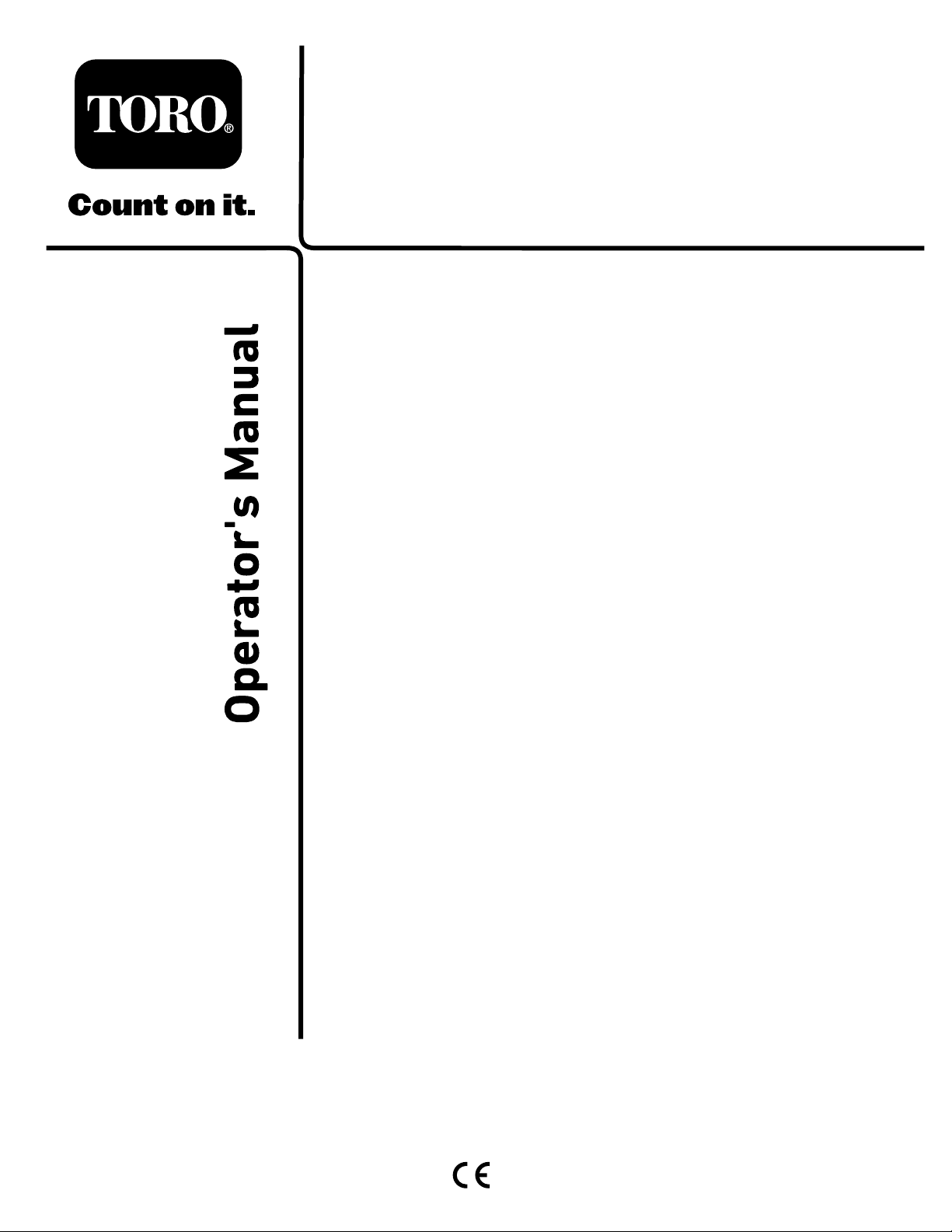
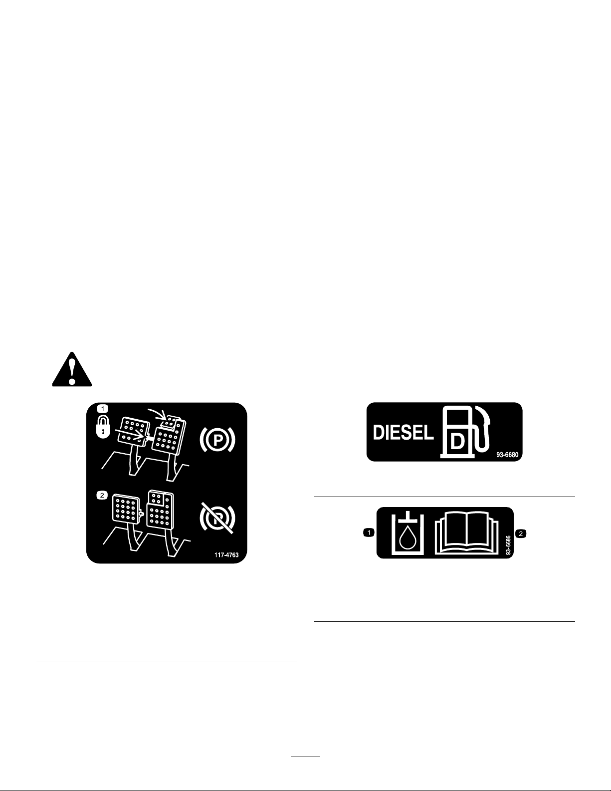
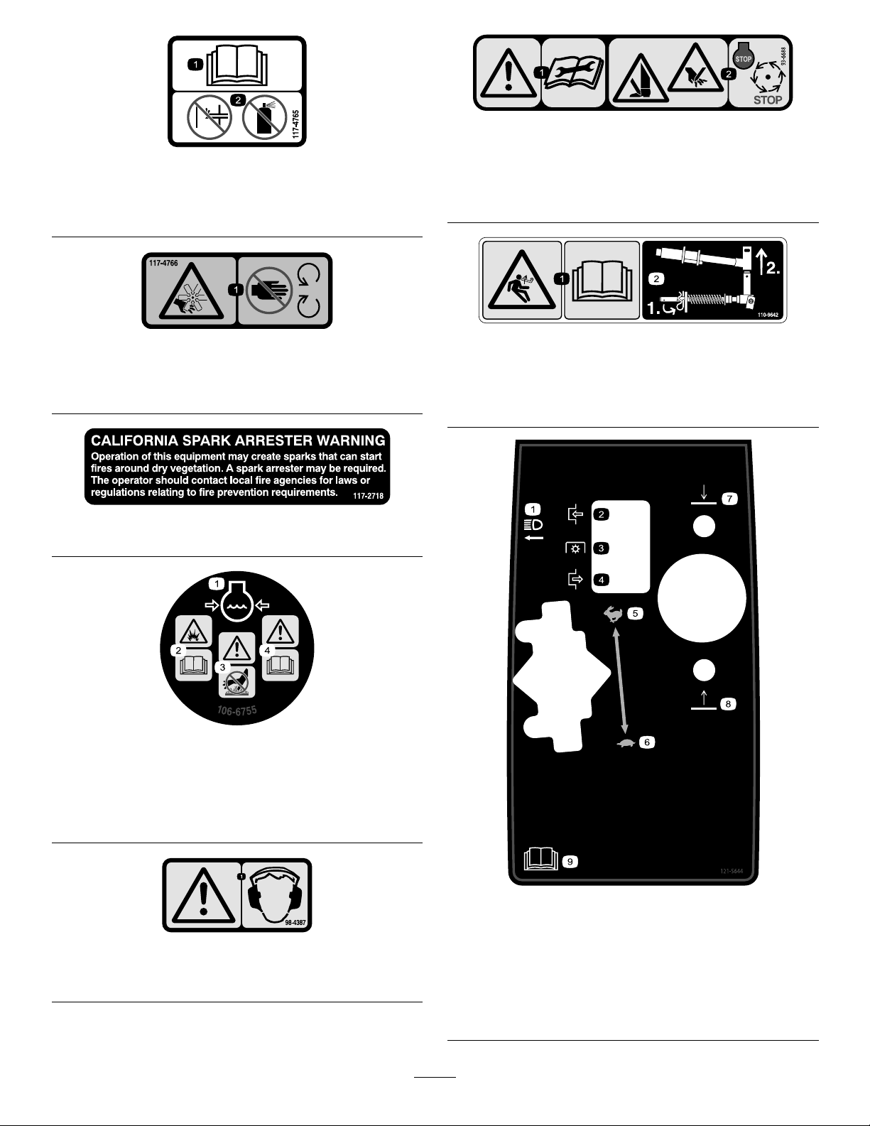
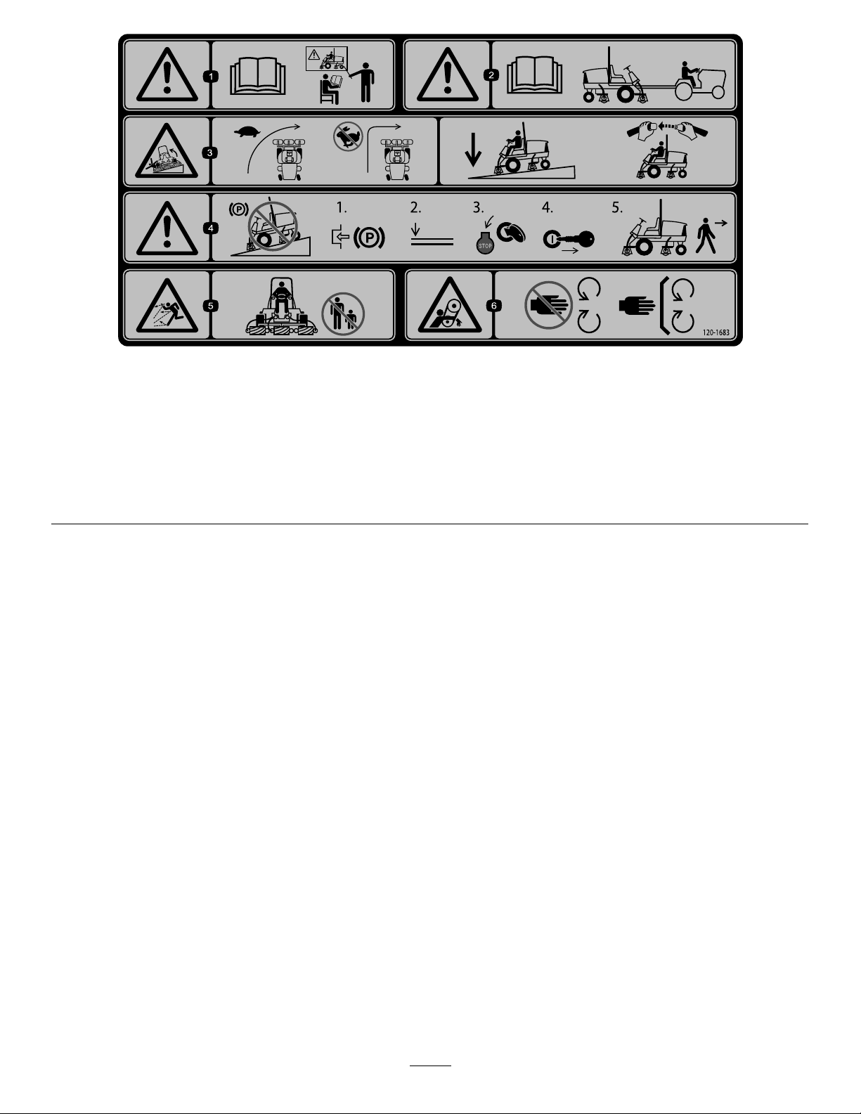
SafetyandInstructionalDecals.................................4
Setup...........................................................................10
1AdjustingtheSupportRollers................................11
2ReplacingtheWarningDecalforCE
Compliance........................................................11
3InstallingtheHoodLockforCE
Compliance........................................................11
4InstallingtheCuttingUnits....................................13
5AdjustingtheTurf-CompensationSpring................16
6UsingtheCutting-UnitKickstand...........................16
7GreasingtheMachine...........................................17
8CheckingtheFluidLevels.....................................18
9UsingtheGaugeBar............................................18
ProductOverview.........................................................19
Controls...............................................................19
Specications........................................................25
TractionUnitSpecications.....................................25
Attachments/Accessories........................................25
Operation....................................................................26
BeforeOperationSafety..........................................26
ThinkSafetyFirst...................................................26
CheckingtheLeveloftheEngineOil.........................26
CheckingtheCoolingSystem...................................27
FillingtheFuelTank...............................................28
CheckingtheLeveloftheHydraulicFluid..................29
CheckingtheTirePressure......................................30
DuringOperationSafety.........................................31
StartingandShuttingOfftheEngine.........................32
AdjustingtheLift-ArmCounterbalance.....................32
AdjustingtheLift-ArmTurnaroundPosition..............33
FoldingtheROPS..................................................33
CheckingtheInterlockSwitches...............................34
AfterOperationSafety............................................34
PushingorTowingtheMachine...............................34
HaulingtheMachine...............................................36
IdentifyingtheJackingPoints...................................36
IdentifyingtheTie-DownPoints..............................36
OperatingCharacteristics........................................36
OperatingTips......................................................37
Maintenance.................................................................38
RecommendedMaintenanceSchedule(s)......................38
DailyMaintenanceChecklist....................................39
ServiceIntervalChart.............................................40
Pre-MaintenanceProcedures......................................41
Pre-MaintenanceSafety...........................................41
RemovingtheHood...............................................41
Lubrication...............................................................42
GreasingtheBearingsandBushings..........................42
EngineMaintenance..................................................43
EngineSafety.........................................................43
ServicingtheAirCleaner.........................................43
ServicingtheEngineOilandFilter............................44
AdjustingtheThrottle.............................................45
FuelSystemMaintenance...........................................46
DrainingtheFuelTank...........................................46
CheckingtheFuelLinesandConnections..................46
ServicingtheWaterSeparator..................................46
CleaningtheFuel-IntakeScreen...............................46
ElectricalSystemMaintenance....................................47
ElectricalSystemSafety...........................................47
ChargingandConnectingtheBattery........................47
ServicingtheBattery...............................................48
CheckingtheFuses.................................................48
DriveSystemMaintenance.........................................50
CheckingtheTorqueoftheWheelNuts.....................50
CheckingthePlanetaryGearDriveOil......................50
ChangingthePlanetaryGearDriveOil......................50
CheckingtheOilLeveloftheRearAxle.....................51
ChangingtheOilintheRearAxle.............................52
CheckingtheLubricantintheGearBoxofthe
RearAxle...........................................................52
AdjustingtheTractionDriveforNeutral....................52
CheckingtheRear-WheelToe-In..............................53
CoolingSystemMaintenance......................................54
CoolingSystemSafety.............................................54
ServicingtheEngineCoolingSystem........................54
BrakeMaintenance....................................................55
AdjustingtheServiceBrakes....................................55
BeltMaintenance......................................................55
ServicingtheAlternatorBelt....................................55
HydraulicSystemMaintenance....................................56
HydraulicSystemSafety..........................................56
ChangingtheHydraulicFluid...................................56
ReplacingtheHydraulicFilters.................................56
CheckingtheHydraulicLinesandHoses....................57
CuttingUnitMaintenance...........................................58
CuttingUnitSafety.................................................58
BacklappingtheCuttingUnits..................................58
Storage........................................................................59
PreparingtheTractionUnit.....................................59
PreparingtheEngine..............................................59
3

Safety
ThismachinehasbeendesignedtomeetorexceedENISO
5395:2013(whenappropriatedecalsareapplied),andANSI
B71.4-2012.
GeneralSafety
Thisproductiscapableofamputatinghandsandfeetand
ofthrowingobjects.Alwaysfollowallsafetyinstructionsto
avoidseriouspersonalinjury.
Usingthisproductforpurposesotherthanitsintendeduse
couldprovedangeroustoyouandbystanders.
•ReadandunderstandthecontentsofthisOperator’sManual
beforestartingtheengine.
•Donotputyourhandsorfeetnearmovingcomponents
ofthemachine.
•Donotoperatethemachinewithoutallguardsandother
safetyprotectivedevicesinplaceandworkingonthe
machine.
•Keepclearofanydischargeopening.Keepbystanders
andpetsasafedistanceawayfromthemachine.
•Keepchildrenoutoftheoperatingarea.Neverallow
childrentooperatethemachine.
•Stopthemachineandshutofftheenginebeforeservicing,
fueling,oruncloggingthemachine.
Improperlyusingormaintainingthismachinecanresult
ininjury.Toreducethepotentialforinjury,complywith
thesesafetyinstructionsandalwayspayattentiontothe
safety-alertsymbol,whichmeansCaution,Warning,or
Danger—personalsafetyinstruction.Failuretocomplywith
theseinstructionsmayresultinpersonalinjuryordeath.
Youcanndadditionalsafetyinformationwhereneeded
throughoutthisOperator’sManual.
Engine-EmissionCertication
TheengineinthismachineisEUStage3Acompliant.
SafetyandInstructionalDecals
Safetydecalsandinstructionsareeasilyvisibletotheoperatorandarelocatednearanyareaofpotential
danger.Replaceanydecalthatisdamagedorlost.
decal117-4763
117-4763
1.Toengagetheparking
brake,securethebrake
pedalswiththelockingpin,
presstheparkingbrake
pedalsandengagethetoe
pedal.
2.Todisengagetheparking
brake,disengagethe
lockingpinandreleasethe
pedals.
decal93-6680
93-6680
decal93-6686
93-6686
1.Hydraulicoil
2.ReadtheOperator'sManual.
4

decal117-4765
117-4765
1.ReadtheOperator'sManual.
2.Donotusestartingaids.
decal117-4766
117-4766
1.Cutting/dismembermenthazard;fan—stayawayfrom
movingparts.
decal117-2718
117–2718
decal106-6755
106-6755
1.Enginecoolantunder
pressure.
3.Warning—donottouchthe
hotsurface.
2.Explosionhazard—read
theOperator'sManual.
4.Warning—readthe
Operator'sManual.
decal98-4387
98-4387
1.Warning—wearhearingprotection.
decal93-6688
93-6688
1.Warning—readthe
instructionsbefore
servicingorperforming
maintenance.
2.Cuttinghazardofhandor
foot—stoptheengineand
waitformovingpartsto
stop.
decal110-9642
110-9642
1.Storedenergyhazard—readtheOperator'sManual.
2.Movethecotterpintotheholeclosesttotherodbracket
andthenremovetheliftarmandpivotyoke.
decal121-5644
121–5644
1.Lightswitch6.Slow
2.Engage7.Lower
3.Powertake-off8.Raise
4.Disengage9.ReadtheOperator’s
Manual.
5.Fast
5

decal121-3887
121–3887
1.ReadtheOperator’sManual.
decal121-3884
121–3884
1.Engine—stop3.Engine—start
2.Engine—preheat
decal112-5019
112-5019
decal93-6681
93–6681
1.Cutting/dismembermenthazard—stayawayfrommoving
parts.
decal106-6754
106-6754
1.Warning—donottouchthehotsurface.
2.Cutting/dismembermenthazard,fanandentanglement
hazard,belt—stayawayfrommovingparts.
decal125-4605
125–4605
1.Powerseat,10A6.Powersupplied,10A
2.Worklight,10A7.Controller,2A
3.Engine,10A8.Powersupplied,7.5A
4.Cigarettelighter,10A9.Controller,2A
5.Infocenter,2A10.Enginepreheat,60A
6

decal120-1670
120-1670
1.Tractionunitspeed3.Fast
2.Slow
decal130-1651
130-1651
1.ReadtheOperator'sManualformoreinformationof
servicingthemachine.
decalbatterysymbols
BatterySymbols
Someorallofthesesymbolsareonyourbattery.
1.Explosionhazard6.Keepbystandersasafe
distancefromthebattery.
2.Nore,opename,or
smoking
7.Weareyeprotection;
explosivegasescan
causeblindnessandother
injuries.
3.Causticliquid/chemical
burnhazard
8.Batteryacidcancause
blindnessorsevereburns.
4.Weareyeprotection.9.Flusheyesimmediately
withwaterandgetmedical
helpfast.
5.ReadtheOperator's
Manual.
10.Containslead;donot
discard
7

decal120-1683
120-1683
1.Warning—readtheOperator'sManual;donotoperatethe
machineunlessyouhavereceivedtraining.
4.Warning—donotparkthemachineonslopes;engagethe
parkingbrake,lowerthecuttingunits,shutofftheengine,and
removetheignitionkeybeforeleavingthemachine.
2.Warning—readtheOperator'sManualbeforetowingthe
machine.
5.Thrownobjecthazard—keepbystandersasafedistance
awayfromthemachine.
3.Tippinghazard—slowmachinebeforeturning,donotturnat
highspeeds;lowerthecuttingunitswhendrivingdownslopes;
usearolloverprotectionsystemandweartheseatbelt.
6.Entanglementhazard,belt—stayawayfrommovingparts,
keepallguardsandshieldsinplace.
8

decal120-1686
120-1686
(AfxoverPartNo.120-1683forCE)
*ThissafetydecalincludesaslopewarningrequiredonthemachineforcompliancetotheEuropeanLawnMowerSafetyStandardENISO5395:2013.Theconservative
maximumslopeanglesindicatedforoperationofthismachineareprescribedbyandrequiredbythisstandard.Thismachinecomplieswiththeindustry
standardstabilitytestinthestaticlateralandlongitudinaltestswiththemaximumrecommendedslopeindicatedonthe
decal.ReviewtheinstructionsforoperatingthemachineonslopesintheOperator'sManualandtheconditionsinwhich
themachineisbeingoperatedtodeterminewhetherthemachinecanbeoperatedintheconditionsonthatdayandatthat
site.Changesintheterraincanresultinachangeinslopeoperationforthemachine.Ifpossible,keepthe
cuttingunitsloweredtothegroundwhileoperatingthemachineonslopes.Raisingthecuttingunitswhile
operatingonslopescancausethemachinetobecomeunstable.
1.Warning—readtheOperator'sManual;donotoperatethe
machineunlessyouhavereceivedtraining.
4.Warning—donotparkthemachineonslopes;engagethe
parkingbrake,lowerthecuttingunits,shutofftheengine,and
removetheignitionkeybeforeleavingthemachine.
2.Warning—readtheOperator'sManualbeforetowingthe
machine.
5.Thrownobjecthazard—keepbystandersasafedistance
awayfromthemachine.
3.Tippinghazard—donotturnathighspeeds;donotdriveup
ordownslopesgreaterthan16degrees;donotdriveacross
slopesgreaterthan22degrees;lowerthecuttingunitswhen
drivingdownslopes;usearolloverprotectionsystemand
weartheseatbelt.
6.Entanglementhazard,belt—stayawayfrommovingparts,
keepallguardsandshieldsinplace.
9

Setup
LooseParts
Usethechartbelowtoverifythatallpartshavebeenshipped.
ProcedureDescriptionQty.Use
1Nopartsrequired–Adjustthesupportrollers.
2Warningdecal1ReplacethedecalforCECompliance.
Hood-lockbracket1
Rivet2
Screw(1/4x2inch)1
Flatwasher(1/4inch)2
3
Locknut(1/4inch)1
InstallthehoodlockforEuropeanCE
Compliance.
Fronthoseguide(right)1
4Fronthoseguide(left)1Installthecuttingunits.
5Nopartsrequired–Adjusttheturf-compensationspring.
6Cutting-unitkickstand1Usethecutting-unitkickstand.
7Nopartsrequired–Greasethemachine.
8Nopartsrequired–Checkthelevelsoftherearaxle
lubricant,hydraulicuid,andengineoil.
9Gaugebar1Usethegaugebartoadjustthecutting
unit.
MediaandAdditionalParts
DescriptionQty.Use
Operator'sManual1Readthemanualbeforeoperatingthemachine.
Engineowner'smanual1Readthemanualbeforeoperatingtheengine.
Operatortrainingmaterial1Viewthetrainingmaterialbeforeoperatingthemachine.
DeclarationofConformity1ThisdocumentindicatesCEcompliance.
Note:Determinetheleftandrightsidesofthemachinefromthenormaloperatingposition.
10

1
AdjustingtheSupportRollers
NoPartsRequired
Procedure
Dependingonwhatwidthcuttingunitsaretobeinstalledon
thetractionunit,adjustthesupportrollersasfollows:
Parkthemachineonalevelsurface,engagetheparkingbrake,
shutofftheengine,andremovethekey.
•Ifusing27inchcuttingunits,installtherollersinthe
uppermountingholesofthesupportassemblychannels
(Figure3).
•Ifusing32inchcuttingunits,installtherollersinthe
lowermountingholesofsupportassemblychannels
(Figure3).
g019541
1
2
3
g019541
Figure3
1.Supportassemblychannel3.Usethisholefor32inch
cuttingunits.
2.Usethisholefor27inch
cuttingunits.
2
ReplacingtheWarningDecal
forCECompliance
Partsneededforthisprocedure:
1Warningdecal
Procedure
OnmachinesrequiringCECompliance,afxtheCEwarning
decal(PartNo.120-1686)overthestandardwarningdecal
(PartNo.120-1683).
3
InstallingtheHoodLockfor
CECompliance
Partsneededforthisprocedure:
1Hood-lockbracket
2Rivet
1Screw(1/4x2inch)
2Flatwasher(1/4inch)
1Locknut(1/4inch)
Procedure
1.Unhookthehoodlatchfromthehood-latchbracket
(Figure4).
11

g200373
Figure4
1.Hoodlatch
2.Removethe2rivetssecuringthehood-latchbracketto
thehood(Figure5).
G012628
1
2
g012628
Figure5
1.Hood-latchbracket2.Rivets
3.Removethehood-latchbracketfromthehood.
4.Whilealigningthemountingholes,positiontheCE
lockbracketandthehood-latchbracketontothehood.
Note:Thelockbracketmustbeagainstthehood
(Figure5).
Donotremoveboltandnutassemblyfromthe
lock-bracketarm.
G012629
1
2
g012629
Figure6
1.CElockbracket2.Boltandnutassembly
5.Alignthewasherswiththeholesontheinsideofthe
hood.
6.Rivetthebracketsandthewasherstothehood(Figure
6).
7.Hookthelatchontothehood-latchbracket(Figure7).
G012630
1
g012630
Figure7
1.Hoodlatch
8.Screwtheboltintotheotherarmofhood-lockbracket
tolockthelatchinposition(Figure8).
G012631
1
2
3
g012631
Figure8
1.Bolt3.Armofthehood-lock
bracket
2.Nut
12

9.Tightentheboltsecurelybutdonottightenthenut.
4
InstallingtheCuttingUnits
Partsneededforthisprocedure:
1Fronthoseguide(right)
1Fronthoseguide(left)
Procedure
1.Removethereelmotorsfromtheshippingbrackets.
2.Removeanddiscardtheshippingbrackets.
3.Removethecuttingunitsfromthecartons.
4.Assembleandadjustasdescribedinthecuttingunit
Operator'sManual.
5.Makesurethatthecounterweight(Figure9)isinstalled
totheproperendofthecuttingunitasdescribedinthe
cuttingunitOperator'sManual.
g003320
Figure9
1.Counterweight
6.Allofthecuttingunitsareshippedwiththeturf
compensationspringmountedtotherightsideofthe
cuttingunit.Theturfcompensationspringmustbe
mountedtothesamesideofthecuttingunitasthe
reeldrivemotor.Repositiontheturfcompensation
asfollows:
A.Removethe2carriageboltsandnutssecuringthe
rodbrackettothecutting-unittabs(Figure10).
g003949
Figure10
1.Turfcompensationspring3.Springtube
2.Rodbracket
B.Removetheangenutsecuringthespring-tube
bolttothecarrier-frametab(Figure10)
C.Removetheassembly.
D.Mountthespring-tubebolttotheoppositetabon
thecarrierframeandsecurewiththeangenut.
Note:Positiontheboltheadtotheoutersideof
thetabasshowninFigure11.
g003967
Figure11
1.Oppositecarrierframetab2.Rodbracket
E.Mounttherodbrackettothecuttingunittabs
withthecarriageboltsandnuts(Figure11).On
thecuttingunit,mountthelefthoseguidetothe
frontofthecuttingunittabswhenreinstallingthe
rodbracket(Figure13).
Important:OnCuttingUnit4(leftfront)
andCuttingUnit5(rightfront),usethe
rod-bracketmountingnutstoinstallthehose
guidestothefrontofthecutting-unittabs.
Thehoseguidesshouldleantowardthecenter
cuttingunit(Figure12throughFigure14).
13

g031275
Figure12
1.Cuttingunit15.Cuttingunit5
2.Cuttingunit26.Reelmotor
3.Cuttingunit37.Weight
4.Cuttingunit4
g015160
Figure13
1.Hoseguide(leftside
shown)
3.Nuts
2.Rodbracket
g019602
11
g019602
Figure14
1.Hoseguides(eachmustleantowardthecentercuttingunit)
Note:Wheninstallingorremovingthecutting
units,makesurethatthehairpincotterisinstalled
inthespring-rodholenexttotherodbracket.
Otherwise,thehairpincottermustbeinstalledin
theholeintheendoftherod.
7.Increasethesteeringontherearcuttingunitsby
removingthe2pivotspacers,hex-socketscrews,and
angelocknuts(Figure15)fromthecarrierframesof
therearcuttingunits(CuttingUnits2and3);referto
Figure12.
14

g033150
Figure15
1.Hex-socketscrew3.Carrierframe
2.Pivotspacer4.Flangelocknut
8.Loweralloftheliftarmscompletely.
9.Coatthecarrier-frameshaftwithcleangrease(Figure
16).
G015976
1
2
3
4
5
g015976
Figure16
1.Lift-armpivotyoke4.Carrier-frameshaft
2.Liftarm5.Thrustwasher
3.Klikpin
10.Forthefrontcuttingunits,slideacuttingunitunder
theliftarmwhileinsertingtheshaftofthecarrier
frameupintothelift-armpivotyoke(Figure16).Make
surethatthethrustwasherisinpositiononthecarrier
frameshaft.
11.Securethecarrier-frameshafttothelift-armyokewith
theklikpin(Figure16).
12.Tolock(x)thesteeringonthecuttingunits,secure
thepivotyoketothecarrierframewiththesnapper
pin(Figure17).
1
G015977
g015977
Figure17
1.Snapperpin
Note:Fixedsteeringisrecommendedwhen
cuttingonsidehills.
13.Usethefollowingprocedureontherearcuttingunits
whentheheightofcutisabove19mm(3/4inch).
A.Removethelynchpinandwashersecuringthe
lift-armpivotshafttotheliftarmandslidethe
lift-armpivotshaftoutoftheliftarm(Figure18).
g003979
Figure18
1.Lift-armpivot-shaftlynchpinandwasher
B.Insertthelift-armyokeontothecarrierframe
shaft(Figure16).
C.Insertthelift-armshaftintotheliftarmand
secureitwiththewasherandthelynchpin(Figure
18).
14.Securethelift-armchaintothechainbracketwiththe
snapperpin(Figure19).
15

Note:Usethenumberofchainlinksdescribedinthe
cuttingunitOperator'sManual.
g003948
Figure19
1.Lift-armchain3.Snapperpin
2.Chainbracket
15.Coatthesplineshaftofthereelmotorwithclean
grease.
16.OilthereelmotorO-ringandinstallitontothemotor
ange.
17.Installthemotorbyrotatingitclockwisesothatthe
motorangesclearthebolts(Figure20).
g004127
Figure20
1.Reel-drivemotor2.Mountingbolts
18.Rotatethemotorcounterclockwiseuntiltheanges
encirclethebolts,andthentightenthebolts.
Important:Makesurethatthereelmotorhoses
arenottwisted,kinked,oratriskofbeingpinched.
5
Adjustingthe
Turf-CompensationSpring
NoPartsRequired
Procedure
Theturf-compensationspring(Figure21)transferstheweight
fromthefronttotherearroller.Thishelpstoreduceawave
patternintheturf,alsoknownasmarcellingorbobbing.
Important:Makespringadjustmentswiththecutting
unitmountedtothetractionunit,pointingstraight
aheadandloweredtotheshopoor.
1.Makesurethatthehairpincotterisinstalledintherear
holeinthespringrod(Figure21).
Note:Whenservicingthecuttingunit,movethe
hairpincottertothespring-rodholenexttothe
turf-compensationspring.
g003863
Figure21
1.Turf-compensationspring3.Springrod
2.Hairpincotter4.Hexnuts
2.Tightenthehexnutsonthefrontendofthespringrod
untilthecompressedlengthofthespringis15.9cm
(6.25inches);refertoFigure21.
Note:Whenoperatingonroughterraindecreasethe
springlengthby13mm(1/2inch).Groundfollowing
willbeslightlydecreased.
Note:Theturfcompensationsettingwillneedtobe
resetiftheHOCsettingortheAggressivenessofCut
settingischanged.
16

6
UsingtheCutting-Unit
Kickstand
Partsneededforthisprocedure:
1Cutting-unitkickstand
Procedure
Wheneverthecuttingunithastobetippedtoexposethe
bedknife/reel,propuptherearofthecuttingunitwiththe
kickstandtomakesurethatthenutsonthebackendofthe
bedbaradjustingscrewsarenotrestingontheworksurface
(Figure22).
g003985
Figure22
1.Cuttingunitkickstand
Securethekickstandtothechainbracketwiththesnapper
pin(Figure23).
g004144
Figure23
1.Chainbracket3.Cutting-unitkickstand
2.Snapperpin
7
GreasingtheMachine
NoPartsRequired
Procedure
Beforethemachineisoperated,itmustbegreasedtoensure
properlubrication.RefertoLubrication(page42).Failureto
properlygreasethemachinewillresultinprematurefailureof
criticalparts.
17

8
CheckingtheFluidLevels
NoPartsRequired
Procedure
1.Checktheleveloftherearaxlelubricantbeforethe
engineisrststarted,refertoCheckingtheOilLevel
oftheRearAxle(page51).
2.Checkthelevelofthehydraulicuidbeforetheengine
isrststarted,refertoCheckingtheLevelofthe
HydraulicFluid(page29).
3.Checktheleveloftheengineoilbeforeandafterthe
engineisrststarted,refertoCheckingtheLevelof
theEngineOil(page26).
9
UsingtheGaugeBar
Partsneededforthisprocedure:
1Gaugebar
Procedure
Usethegaugebartoadjustthecuttingunit.Refertothe
cuttingunitOperator'sManualfortheadjustmentprocedures
(Figure24).
g004552
Figure24
1.Gaugebar4.Holesusedforsettingthe
groomerheightofgroom
(HOG)
2.Height-adjustingscrew5.Holenotused
3.Nut
18

ProductOverview
Controls
BrakePedals
The2footpedals(Figure25)operateindividualwheelbrakes
forturningassistanceandtoaidinobtainingbettersidehill
traction.
Pedal-LockingLatch
Thepedal-lockinglatch(Figure25)connectsthepedals
togethertoengagetheparkingbrake.
Parking-BrakePedal
Toengagetheparkingbrake,(Figure25)connectthepedals
togetherwiththepedal-lockinglatch,pushdownonthe
rightbrakepedalwhileengagingthetoepedal.Torelease
theparkingbrake,press1ofthebrakepedalsuntilthe
parking-brakelatchretracts.
g015074
Figure25
1.Brakepedal4.Tractionpedal
2.Pedal-lockinglatch5.Tilt-steeringpedal
3.Parking-brakepedal
TractionPedal
Thetractionpedal(Figure25)controlsforwardandreverse
operation.Pressthetopofthepedaltomoveforwardand
thebottomtomovebackward.Groundspeedisdetermined
byhowfaryoupressthepedal.Formaximumgroundspeed,
fullypressthepedalwhilethethrottleisintheFASTposition.
Tostopthemachine,reduceyourfootpressureonthe
tractionpedalandallowittoreturntothecenterposition.
TiltSteeringPedal
Totiltthesteeringwheeltowardsyou,pressthefootpedal
(Figure25)down,andpullthesteeringtowertowardyouto
themostcomfortablepositionandthenreleasethepedal.
Mow-SpeedLimiter
Whenthemow-speedlimiter(Figure26)isippedupitwill
controlthemowspeedandallowthecuttingunitstobe
engaged.Eachspaceradjuststhemowingspeedby0.8km/h
(½mileperhour).Themorespacersthatthereareonthe
topofthebolt,theslowerthemachinegoes.Fortransport,
ipbackthemow-speedlimiterandthemachinewillhave
maximumtransportspeed.
Speed-LimiterScrews
Adjustthescrew(s)(Figure26)tolimittheamountthe
tractionpedalcanbepressedintheforwardorreverse
directiontolimitspeed.
Important:Thespeed-limiterscrewmuststopthe
tractionpedalbeforethepumpreachesfullstrokeor
damagetothepumpmayoccur.
g015075
Figure26
1.Reversespeedlimiter
screw
3.Spacers
2.Forwardspeedlimiter
screw
4.Mowspeedlimiter
LowerMow/RaiseControlLever
Thislever(Figure27)raisesandlowersthecuttingunitsand
alsostartsandstopsthereelswhenthereelsareenabledin
themowmode.Thecuttingunitscannotbeloweredwhen
themow/transportleverisinthetransportposition.
KeySwitch
Thekeyswitch(Figure27)has3positions:OFF,
ON/PREHEAT,andSTART.
InfoCenter
TheInfoCenterLCDdisplayshowsinformationaboutyour
machinesuchastheoperatingstatus,variousdiagnosticsand
otherinformationaboutthemachine(Figure27).
PTOSwitch
ThePTOswitch(Figure27)has2positions:STARTandSTOP.
PushthePTObuttonforwardtoengagethecutting-unit
19

blades.Pushthebuttonbacktodisengagethecutting-unit
blades.
g025902
Figure27
1.Lowermow/raisecontrol
lever
4.PTOswitch
2.Keyswitch5.Engine-speedswitch
3.InfoCenter6.Headlightswitch
Engine-SpeedSwitch
Theengine-speedswitch(Figure27)has2modestochange
theenginespeed.Bymomentarilytappingtheswitch,the
enginespeedcanbeincreasedordecreasedin100rpm
increments.Byholdingtheswitchdowntheenginewill
automaticallymovetoHighorLowidle,dependingonwhich
endoftheswitchispressed.
HeadlightSwitch
Pivottheswitchdownwardtoturnontheheadlights(Figure
27).
PowerPoint
Usethepowerpoint(Figure28)topoweroptional12V
electricalaccessories.
g033267
Figure28
1.Powerpoint
BagHolder
Usethebagholder(Figure29)forstorage.
g033325
Figure29
1.Bagholder
BacklapLevers
Usethebacklapleversforbacklappingthereels(Figure30).
g015076
Figure30
1.Frontbacklaplever2.Rearbacklaplever
20
Other manuals for 03781
1
Table of contents
Other Toro Tractor manuals

Toro
Toro 79114 User manual

Toro
Toro Wheel Horse 523Dxi User manual

Toro
Toro Wheel Horse Recycler 78355 User manual

Toro
Toro 25430 User manual

Toro
Toro 25545T User manual

Toro
Toro 25450W User manual

Toro
Toro WorkmanR e2050 User manual

Toro
Toro Wheel Horse 520xi User manual

Toro
Toro 08743 User manual

Toro
Toro Groundsmaster 7200 Series User manual

Toro
Toro Reelmaster 5610 User manual

Toro
Toro 25430A User manual

Toro
Toro 03200 Reelmaster 3100-D User manual

Toro
Toro Maxi Sneaker 370 User manual

Toro
Toro 8703 User manual

Toro
Toro 08885 User manual

Toro
Toro 8886 User manual

Toro
Toro 13AX60RG544 User manual

Toro
Toro Wheel Horse 73560 User manual

Toro
Toro 03781TE User manual