Toro 04591 User manual

Form No. 3463-797 Rev A
Greensmaster
®
eT riFlex 3370
T raction Unit
Model No. 04591 —Serial No. 400000000 and Up
Register at www .T oro.com.
Original Instructions (EN)
*3463-797*

This product complies with all relevant European
directives; for details, please see the separate product
specic Declaration of Conformity (DOC) sheet.
W ARNING
CALIFORNIA
Proposition 65 W arning
The power cord on this product contains
lead, a chemical known to the State
of California to cause birth defects
or other reproductive harm. W ash
hands after handling.
Battery posts, terminals, and related
accessories contain lead and lead
compounds, chemicals known to
the State of California to cause
cancer and reproductive harm. W ash
hands after handling.
Use of this product may cause exposure
to chemicals known to the State of
California to cause cancer , birth defects,
or other reproductive harm.
Introduction
This machine is a ride-on, reel-blade greens mower
intended to be used by professional, hired operators
in commercial applications. It is primarily designed
for cutting grass on well-maintained turf. Using this
product for purposes other than its intended use could
prove dangerous to you and bystanders.
Read this information carefully to learn how to operate
and maintain your product properly and to avoid
injury and product damage. Y ou are responsible for
operating the product properly and safely .
V isit www .T oro.com for more information, including
safety tips, training materials, accessory information,
help nding a dealer , or to register your product.
Whenever you need service, genuine T oro parts, or
additional information, contact an authorized T oro
distributor and have the model and serial numbers of
your product ready . Figure 1 identies the location of
the model and serial numbers on the product. W rite
the numbers in the space provided.
Important: W ith your mobile device, you can
scan the QR code on the serial number decal (if
equipped) to access warranty , parts, and other
product information.
g279286
Figure 1
1. Model and serial number location
Model No.
Serial No.
© 2023—The T oro® Company
81 1 1 L yndale A venue South
Bloomington, MN 55420
2
Contact us at www .T oro.com.
Printed in the USA
All Rights Reserved

Contents
Safety . . . . . . . . . . . . . . . . . . . . . . . . . . . . . . . . . . . . . . . . . . . . . . . . . . . . . . . . . . . . . . . . . . . . . . . 4
General Machine Safety W arnings . . . . . . . . . . . . . . . . . . . . . . 4
Lawn Mower Safety W arnings . . . . . . . . . . . . . . . . . . . . . . . . . . . . 5
Additional Safety Messages . . . . . . . . . . . . . . . . . . . . . . . . . . . . . . . 6
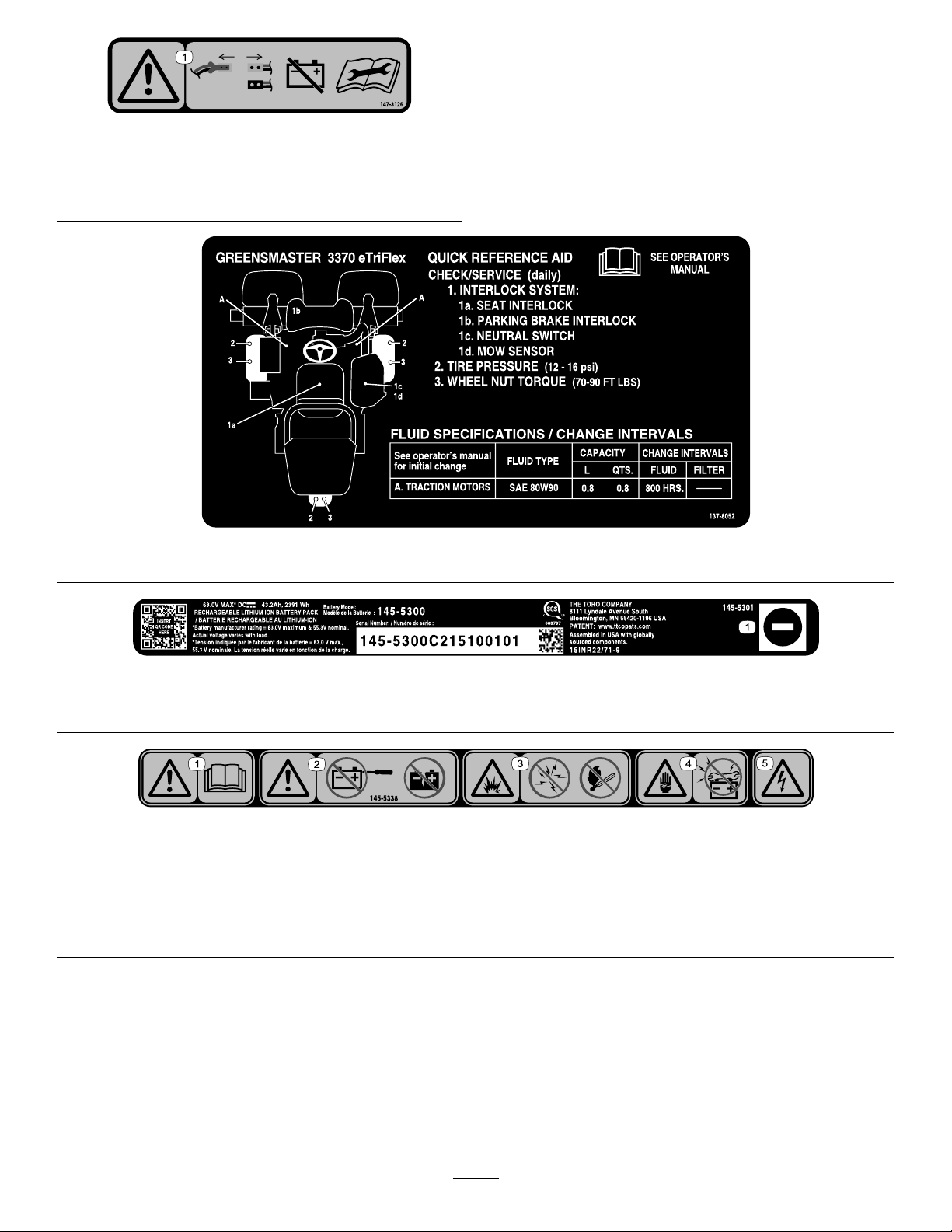
Safety and Instructional Decals . . . . . . . . . . . . . . . . . . . . . . . . . . 7
Setup . . . . . . . . . . . . . . . . . . . . . . . . . . . . . . . . . . . . . . . . . . . . . . . . . . . . . . . . . . . . . . . . . . . . . . . 1 1
1 Installing the Roll Bar . . . . . . . . . . . . . . . . . . . . . . . . . . . . . . . . . . . . . 12
2 Installing the Seat . . . . . . . . . . . . . . . . . . . . . . . . . . . . . . . . . . . . . . . . . . 12
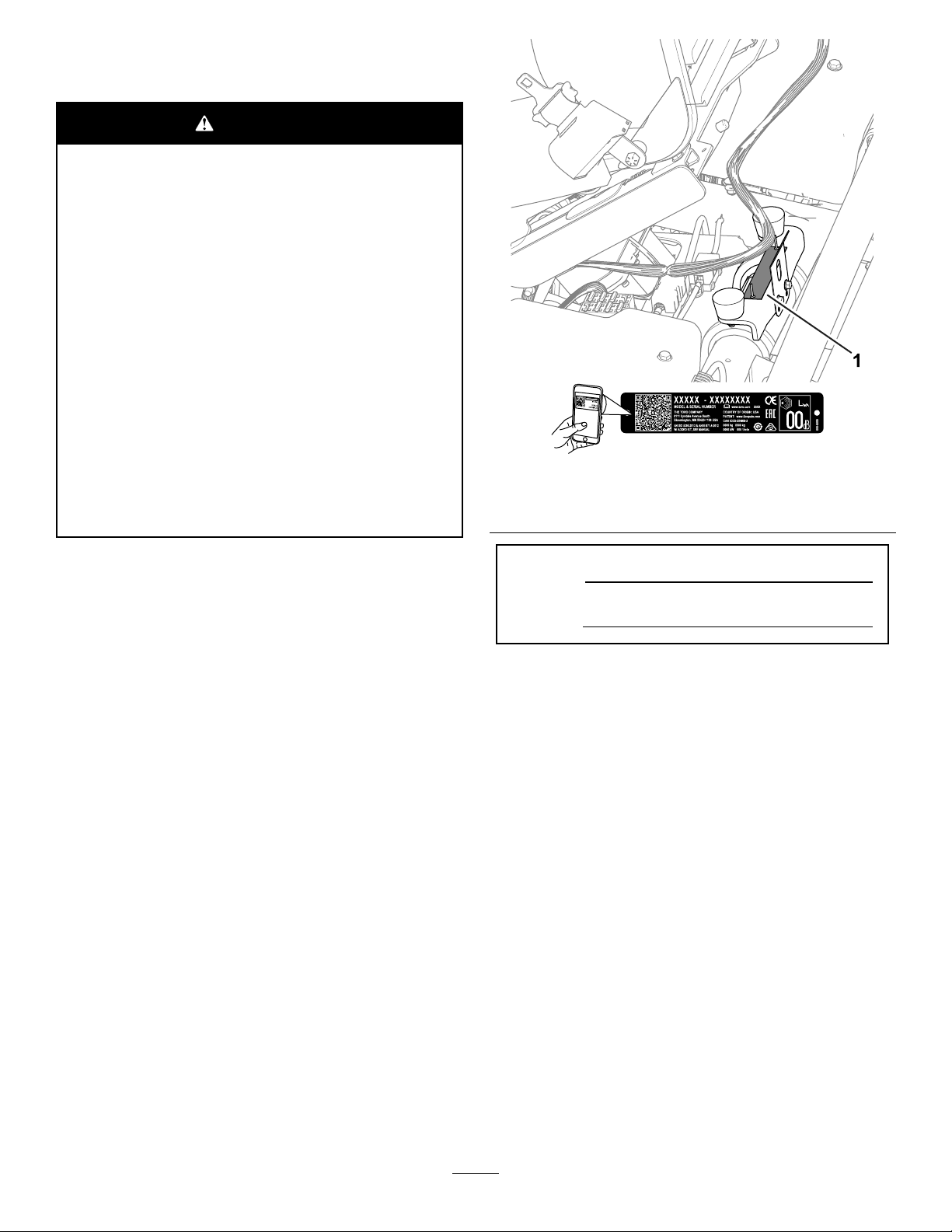
3 Installing the Service Decal . . . . . . . . . . . . . . . . . . . . . . . . . . . . 12
4 Installing the Steering Wheel . . . . . . . . . . . . . . . . . . . . . . . . . . 13
5 Installing the Grass-Basket Hooks . . . . . . . . . . . . . . . . . 13
6 Installing the Cutting Units . . . . . . . . . . . . . . . . . . . . . . . . . . . . . . 13
7 Connecting the Main-Power
Connectors . . . . . . . . . . . . . . . . . . . . . . . . . . . . . . . . . . . . . . . . . . . . . . . . . . . 14
8 Adjusting the Machine Settings . . . . . . . . . . . . . . . . . . . . . . 15
9 Adding Rear W eight . . . . . . . . . . . . . . . . . . . . . . . . . . . . . . . . . . . . . . . 15
10 Installing the CE/UKCA Decals . . . . . . . . . . . . . . . . . . . . 15
1 1 Reducing the T ire Pressure . . . . . . . . . . . . . . . . . . . . . . . . . . 16
12 Mounting the Battery Charger on a
W all . . . . . . . . . . . . . . . . . . . . . . . . . . . . . . . . . . . . . . . . . . . . . . . . . . . . . . . . . . . . . . . 16
13 Charging the Batteries . . . . . . . . . . . . . . . . . . . . . . . . . . . . . . . . . 16
Product Overview . . . . . . . . . . . . . . . . . . . . . . . . . . . . . . . . . . . . . . . . . . . . . . . . . . . 17
Controls . . . . . . . . . . . . . . . . . . . . . . . . . . . . . . . . . . . . . . . . . . . . . . . . . . . . . . . . . . . 17
InfoCenter . . . . . . . . . . . . . . . . . . . . . . . . . . . . . . . . . . . . . . . . . . . . . . . . . . . . . 19
Specications . . . . . . . . . . . . . . . . . . . . . . . . . . . . . . . . . . . . . . . . . . . . . . . . . . 23
Attachments/Accessories . . . . . . . . . . . . . . . . . . . . . . . . . . . . . . . . . 24
Before Operation . . . . . . . . . . . . . . . . . . . . . . . . . . . . . . . . . . . . . . . . . . . . . . . . . 25
Before Operation Safety . . . . . . . . . . . . . . . . . . . . . . . . . . . . . . . . . . . 25
Identifying the Cutting Units . . . . . . . . . . . . . . . . . . . . . . . . . . . . . . 25
Using the InfoCenter to Adjust the Machine
Settings . . . . . . . . . . . . . . . . . . . . . . . . . . . . . . . . . . . . . . . . . . . . . . . . . . . . . . . . . 25
Understanding the InfoCenter Dialog
Messages . . . . . . . . . . . . . . . . . . . . . . . . . . . . . . . . . . . . . . . . . . . . . . . . . . . . . 28
T ilting the Steering Wheel . . . . . . . . . . . . . . . . . . . . . . . . . . . . . . . . . 28
Performing Daily Maintenance . . . . . . . . . . . . . . . . . . . . . . . . . . 29
During Operation . . . . . . . . . . . . . . . . . . . . . . . . . . . . . . . . . . . . . . . . . . . . . . . . . 29
During Operation Safety . . . . . . . . . . . . . . . . . . . . . . . . . . . . . . . . . . . 29
Breaking in the Machine . . . . . . . . . . . . . . . . . . . . . . . . . . . . . . . . . . . 30
T urning On the Machine . . . . . . . . . . . . . . . . . . . . . . . . . . . . . . . . . . . . 30
Checking the Machine after T urning On the
Machine . . . . . . . . . . . . . . . . . . . . . . . . . . . . . . . . . . . . . . . . . . . . . . . . . . . . . . . . 30
Understanding the Safety-Interlock
System . . . . . . . . . . . . . . . . . . . . . . . . . . . . . . . . . . . . . . . . . . . . . . . . . . . . . . . . . . 30
Driving the Machine without Mowing . . . . . . . . . . . . . . . . . 31
Mowing the Green . . . . . . . . . . . . . . . . . . . . . . . . . . . . . . . . . . . . . . . . . . . . 31
Monitoring the Battery-System Charge
Level . . . . . . . . . . . . . . . . . . . . . . . . . . . . . . . . . . . . . . . . . . . . . . . . . . . . . . . . . . . . . 33
Shutting Of f the Machine . . . . . . . . . . . . . . . . . . . . . . . . . . . . . . . . . . 33
After Operation . . . . . . . . . . . . . . . . . . . . . . . . . . . . . . . . . . . . . . . . . . . . . . . . . . . . 33
After Operation Safety . . . . . . . . . . . . . . . . . . . . . . . . . . . . . . . . . . . . . . 33
Inspecting and Cleaning after Mowing . . . . . . . . . . . . . . 35
Hauling the Machine . . . . . . . . . . . . . . . . . . . . . . . . . . . . . . . . . . . . . . . . . 35
T owing the Machine . . . . . . . . . . . . . . . . . . . . . . . . . . . . . . . . . . . . . . . . . . 36
Maintaining the Lithium-Ion Batteries . . . . . . . . . . . . . . . . 37
T ransporting the Lithium-Ion Batteries . . . . . . . . . . . . . . 37
Understanding the Lithium-Ion Battery
Charger . . . . . . . . . . . . . . . . . . . . . . . . . . . . . . . . . . . . . . . . . . . . . . . . . . . . . . . . . 38
Maintenance . . . . . . . . . . . . . . . . . . . . . . . . . . . . . . . . . . . . . . . . . . . . . . . . . . . . . . . . . . . 40
Maintenance Safety . . . . . . . . . . . . . . . . . . . . . . . . . . . . . . . . . . . . . . . . . . 40
Recommended Maintenance Schedule(s) . . . . . . . . . . . 40
Daily Maintenance Checklist . . . . . . . . . . . . . . . . . . . . . . . . . . . . . 41
Pre-Maintenance Procedures . . . . . . . . . . . . . . . . . . . . . . . . . . . . . . 41
Raising the Machine . . . . . . . . . . . . . . . . . . . . . . . . . . . . . . . . . . . . . . . . . 41
Raising the Hood . . . . . . . . . . . . . . . . . . . . . . . . . . . . . . . . . . . . . . . . . . . . . . 43
Electrical System Maintenance . . . . . . . . . . . . . . . . . . . . . . . . . . . 43
Electrical System Safety . . . . . . . . . . . . . . . . . . . . . . . . . . . . . . . . . . . 43
Disconnecting or Connecting Power to the
Machine . . . . . . . . . . . . . . . . . . . . . . . . . . . . . . . . . . . . . . . . . . . . . . . . . . . . . . . . 43
Locating the Fuses . . . . . . . . . . . . . . . . . . . . . . . . . . . . . . . . . . . . . . . . . . . 44
Servicing the Batteries . . . . . . . . . . . . . . . . . . . . . . . . . . . . . . . . . . . . . . 46
Maintaining the Battery Charger . . . . . . . . . . . . . . . . . . . . . . . 46
Drive System Maintenance . . . . . . . . . . . . . . . . . . . . . . . . . . . . . . . . . . 47
Checking the T ire Pressure . . . . . . . . . . . . . . . . . . . . . . . . . . . . . . . 47
Checking the T orque of the Wheel
Nuts .............................................................. 47
Changing the T raction-Motor-Gearbox
Fluid .............................................................. 47
Brake Maintenance . . . . . . . . . . . . . . . . . . . . . . . . . . . . . . . . . . . . . . . . . . . . . 49
Adjusting the Brakes . . . . . . . . . . . . . . . . . . . . . . . . . . . . . . . . . . . . . . . . . 49
Cutting Unit Maintenance . . . . . . . . . . . . . . . . . . . . . . . . . . . . . . . . . . . . . 49
Blade Safety . . . . . . . . . . . . . . . . . . . . . . . . . . . . . . . . . . . . . . . . . . . . . . . . . . . . . 49
Installing and Removing the Cutting
Units .............................................................. 49
Checking the Reel-to-Bedknife Contact . . . . . . . . . . . . 52
Backlapping the Cutting Units . . . . . . . . . . . . . . . . . . . . . . . . . . . 52
Storage . . . . . . . . . . . . . . . . . . . . . . . . . . . . . . . . . . . . . . . . . . . . . . . . . . . . . . . . . . . . . . . . . . . 53
Storage Safety . . . . . . . . . . . . . . . . . . . . . . . . . . . . . . . . . . . . . . . . . . . . . . . . . . 53
Preparing the Machine for Storage . . . . . . . . . . . . . . . . . . . 53
Battery Storage Requirements . . . . . . . . . . . . . . . . . . . . . . . . . 53
Storing the Charger . . . . . . . . . . . . . . . . . . . . . . . . . . . . . . . . . . . . . . . . . . 54
3

Safety
General Machine Safety
W arnings
W ARNING—Read all safety warnings,
instructions, illustrations and specications
provided with this machine.
Failure to follow the warnings and instructions
may result in electric shock, re and/or serious
injury .
The term “machine” in all of the warnings listed below
refers to your mains-operated (corded) machine or
battery-operated (cordless) machine.
1. W ork area safety
A. Keep work area clean and well lit.
Cluttered or dark areas invite accidents.
B. Do not operate the machine in explosive
atmospheres, such as in the presence of
ammable liquids, gasses, or dust. The
machine creates sparks, which may ignite
the dust or fumes.
C. Keep children and bystanders away
while operating the machine. Distractions
can cause you to lose control.
2. Electrical safety
A. Machine plugs must match the outlet.
Never modify the plug in any way . Do not
use any adapter plugs with an earthed
(grounded) machine. Unmodied plugs
and matching outlets will reduce risk of
electric shock.
B. A void body contact with earthed or
grounded surfaces, such as pipes,
radiators, ranges, and refrigerators.
There is an increased risk of electric shock
if your body is earthed or grounded.
C. Do not expose the machine to rain or wet
conditions. W ater entering a machine will
increase the risk of electric shock.
D. Do not abuse the cord. Never use the
cord for carrying, pulling or unplugging
the machine. Keep cord away from
heat, oil, sharp edges, or moving parts.
Damaged or entangled cords increase the
risk of electric shock.
E. When operating the machine outdoors,
use an extension cord suitable for
outdoor use. Use of a cord suitable for
outdoor use reduces the risk of electric
shock.
F . If operating the machine in a damp
location is unavoidable, use a residual
current device (RCD) protected supply .
Use of an RCD reduces the risk of electric
shock.
3. Personal safety
A. Stay alert, watch what you are doing, and
use common sense when operating the
machine. Do not use the machine while
you are tired or under the inuence of
drugs, alcohol, or medication. A moment
of inattention while operating the machine
may result in serious personal injury .
B. Use personal protective equipment.
Always wear eye protection. Protective
equipment such as a dust mask, non-skid
safety shoes, or hearing protection used for
appropriate conditions will reduce personal
injuries.
C. Prevent unintentional starting. Ensure
the switch is in the off-position before
connecting to power source and/or
battery pack. Energising a machine that
has the switch on invites accidents.
D. Remove any adjusting key or wrench
before turning the machine on. A wrench
or a key left attached to a rotating part of
the machine may result in personal injury .
E. Do not overreach. Keep proper footing
and balance at all times. This enables
better control of the machine in unexpected
situations.
F . Dress properly . Do not wear loose
clothing or jewelry . Keep your hair and
clothing away from moving parts. Loose
clothes, jewelry or long hair can be caught
in moving parts.
G. If devices are provided for the
connection of dust extraction and
collection facilities, ensure these are
connected and properly used. Use of
dust collection can reduce dust-related
hazards.
H. Do not let familiarity gained from
frequent use of the machine allow you to
become complacent and ignore machine
safety principles. A careless action can
cause severe injury within a fraction of a
second.
4

4. Machine use and care
A. Do not force the machine. Use the
correct machine for your application.
The correct machine will do the job better
and safer at the rate for which it was
designed.
B. Do not use the machine if the switch
does not turn it on and off. Any machine
that cannot be controlled with the switch is
dangerous and must be repaired.
C. Disconnect the plug from the power
source and/or remove the battery pack,
if detachable, from the machine before
making any adjustments, changing
accessories, or storing the machine.
Such preventive safety measures reduce
the risk of starting the machine accidentally .
D. Store an idle machine out of the reach
of children and do not allow persons
unfamiliar with the machine or these
instructions to operate the machine.
A machine is dangerous in the hands of
untrained users.
E. Maintain the machine and accessories.
Check for misalignment or binding of
moving parts, breakage of parts and
any other condition that may affect the
operation of the machine. If damaged,
have the machine repaired before use.
Many accidents are caused by a poorly
maintained machine.
F . Keep cutting tools sharp and clean.
Properly maintained cutting tools with sharp
cutting edges are less likely to bind and are
easier to control.
G. Use the machine, accessories, and
tool bits etc., in accordance with these
instructions, taking into account the
working conditions and the work to
be performed. Use of the machine for
operations different from those intended
could result in a hazardous situation.
H. Keep handles and grasping surfaces
dry , clean and free from oil and grease.
Slippery handles and grasping surfaces do
not allow for safe handling and control of
the machine in unexpected situations.
5. Battery machine use and care
A. Recharge only with the charger specied
by a manufacturer . A charger that is
suitable for one type of battery pack may
create a risk of re when used with another
battery pack.
B. Use the machine only with specically
designated batteries. Use of any other
batteries may create a risk of injury and re.
C. When battery pack is not in use, keep
it away from other metal objects, like
paper clips, coins, keys, nails, screws
or other small metal objects, that can
make a connection from one terminal
to another . Shorting the battery terminals
together may cause burns or a re.
D. Under abusive conditions, liquid may be
ejected from the battery; avoid contact.
If contact accidentally occurs, ush
with water . If liquid contacts eyes,
additionally seek medical help. Liquid
ejected from the battery may cause irritation
or burns.
E. Do not use a battery pack or machine
that is damaged or modied. Damaged or
modied batteries may exhibit unpredictable
behavior resulting in re, explosion or risk
or injury .
F . Do not expose a battery pack or machine
to re or excessive temperature.
Exposure to re temperature above 130 ° C
may cause an explosion.
G. Follow all charging instructions and do
not charge the battery pack or machine
outside the temperature range specied
in the instructions. Changing improperly
or at temperatures outside the specied
range may damage the battery and increase
the risk of re.
6. Service
A. Have your machine serviced by a
qualied repair person using only
identical replacement parts. This will
ensure that the safety of the machine is
maintained.
B. Never service damaged battery packs.
Service of battery packs should be
performed only by the manufacturer or
authorized service providers.
Lawn Mower Safety
W arnings
A. Do not use the lawnmower in bad weather
conditions, especially when there is a risk
of lightning. This decreases the risk of being
struck by lightning.
B. Thoroughly inspect the area for wildlife
where the lawnmower is to be used. W ildlife
5

may be injured by the lawnmower during
operation.
C. Thoroughly inspect the area where the
lawnmower is to be used and remove all
stones, sticks, wires, bones, and other
foreign objects. Thrown objects can cause
personal injury .
D. Before using the lawnmower , always visually
inspect to see that the blade and the blade
assembly are not worn or damaged. Worn or
damaged parts increase the risk of injury .
E. Keep guards in place. Guards must be in
working order and be properly mounted.
A guard that is loose, damaged, or is not
functioning correctly may result in personal
injury .
F . Keep all cooling air inlets clear of debris.
Blocked air inlets and debris may result in
overheating or risk of re.
G. While operating the lawnmower , always
wear non-slip and protective footwear . Do
not operate the lawnmower when barefoot
or wearing open sandals. This reduces the
chance of injury to the feet from contact with the
moving blade.
H. While operating the lawnmower , always wear
long trousers. Exposed skin increases the
likelihood of injury from thrown objects.
I. Do not operate the lawnmower on
excessively steep slopes. This reduces the
risk of loss of control, slipping and falling which
may result in personal injury .
J. When working on slopes, always be sure of
your footing, always work across the face
of slopes, never up or down and exercise
extreme caution when changing direction.
This reduces the risk of loss of control, slipping
and falling which may result in personal injury .
K. Use extreme caution when reversing or
pulling the lawnmower towards you. Always
be aware of your surroundings. Always be
aware of your surroundings.
L. Do not touch blades and other hazardous
moving parts while they are still in motion.
This reduces the risk of injury from moving parts.
M. When clearing jammed material or cleaning
the lawnmower , make sure all power
switches are off and remove (or activate) the
disabling device. Unexpected operation of the
lawnmower may result in serious personal injury .
Save all warnings and instructionsfor future reference.
Additional Safety Messages
Safety-Alert Symbol
The safety-alert symbol ( Figure 2 ) shown in this
manual and on the machine identies important safety
messages that you must follow to prevent accidents.
g000502
Figure 2
Safety-alert symbol
The safety-alert symbol appears above information
that alerts you to unsafe actions or situations and
is followed by the word DANGER ,W ARNING , or
CAUTION .
DANGER indicates an imminently hazardous situation
which, if not avoided, will result in death or serious
injury .
W ARNING indicates a potentially hazardous situation
which, if not avoided, could result in death or serious
injury .
CAUTION indicates a potentially hazardous situation
which, if not avoided, may result in minor or moderate
injury .
This manual uses two other words to highlight
information. Important calls attention to special
mechanical information and Note emphasizes general
information worthy of special attention.
General Safety
This product is capable of amputating hands and
feet and of throwing objects. Always follow all safety
instructions to avoid serious personal injury or death.
•Read and understand the contents of this
Operator ’ s Manual before turning on the machine.
•Allow only responsible and physically capable
people to operate the machine.
•Use your full attention while operating the
machine. Do not engage in any activity that
causes distractions; otherwise, injury or property
damage may occur .
•Do not put your hands or feet near moving
components of the machine.
•Do not operate the machine without all guards
and other safety protective devices in place and
functioning properly on the machine.
6

•Keep bystanders and children out of the operating
area.
•Shut of f the machine, remove the key , and wait
for all movement to stop before you leave the
operator ’ s position. Allow the machine to cool
before adjusting, servicing, cleaning, or storing it.
Safety and Instructional
Decals
Safety decals and instructions are
easily visible to the operator and are
located near any area of potential
danger . Replace any decal that is
damaged or missing.
decal1 15-8226
1 15-8226
1. T ipping hazard—read the Operator's Manual ; wear a
seatbelt; do not remove the roll bar .
decal1 19-9346
1 19-9346
1. Press the pedal to unlock.
2. Read the Operator's
Manual for more
information.
decal133-8061
133-8061
decal137-8037
137-8037
1. Read the Operator ’ s
Manual for fuse
information.
4. Cutting unit—3
2. Cutting unit—1
5. 3-wheel-drive kit
3. Cutting unit—2
7

decal137-8058
137-8058
1. T raction speed—fast;
reel—transport
5. Lower and engage the
reels.
2. T raction speed—slow;
reel—mow
6. Raise and disengage the
reels.
3. T raction speed—neutral;
reel—backlap
7. On
4. Forward function controls 8. Of f
decal137-8127
137-8127
1. Attention—do not spray with high-pressure water .
decal139-8320
139-8320
1. W arning—all operators
should read the Operator ’ s
Manual and be trained
before operating the
machine.
4. W arning; tipping
hazard—drive slowly
when turning; do not turn
sharply while traveling
fast.
2. Thrown object
hazard—keep bystanders
away .
5. W arning—engage the
parking brake, shut of f
the machine, and remove
the key before leaving the
machine.
3. Cutting/dismemberment
hazard of hand;
cutting/dismemberment
hazard of foot—stay away
from moving parts; keep
all guards and shields in
place.
8

decal139-8321
139-8321
Note: This machine complies with the industry standard
stability test in the static lateral and longitudinal tests with the
maximum recommended slope indicated on the decal. Review the
instructions for operating the machine on slopes in the Operator ’ s
Manual as well as the conditions in which you would operate the
machine to determine whether you can operate the machine in the
conditions on that day and at that site. Changes in the terrain can
result in a change in slope operation for the machine.
1. W arning—all operators
should read the Operator ’ s
Manual and be trained
before operating the
machine.
4. W arning; tipping
hazard—do not use on
slopes greater than 15°.
2. Thrown object
hazard—keep bystanders
away .
5. W arning—engage the
parking brake, shut of f
the machine, and remove
the key before leaving the
machine.
3. Cutting/dismemberment
hazard of hand;
cutting/dismemberment
hazard of foot—stay away
from moving parts; keep
all guards and shields in
place.
decal144-0275
144-0275
1. Batteries are ammable.
decal144-0277
144-0277
1. Positive terminal 4. Do not dispose improperly .
2. Read the Operator ’ s
Manual .
5. Do not expose to re.
3. Recycle the battery .
decal147-0287
147-0287
1. T orque to 2.82 to 3.16 N∙m (25 to 28 in-lb).
decal147-3125
147-3125
1. Keep the battery at
temperatures between 0°
to 45° C (32° to 1 13° F)
when charging; read the
Operator ’ s Manual .
2. W arning—read the
Operator ’ s Manual before
performing maintenance
and charging the battery;
with the main-power
connectors connected,
connect the charger to
the machine charging
connector and do not
engage the reels or
operate the machine;
disconnect the charger
to engage the reels and
operate the machine..
9

decal147-3126
147-3126
1. W arning–disconnect the main-power connectors to
disconnect the battery power; read the Operator ’ s Manual
before performing maintenance.
decal137-8052
137-8052
decal145-5301
145-5301
1. Negative battery terminal
decal145-5338
145-5338
1. W arning—read the Operator ’ s Manual . 4. Electric shock hazard—do not perform maintenance on the
battery .
2. W arning—do not open the battery; do not use a damaged
battery .
5. Electric shock hazard
3. Explosion hazard—do not expose to sparks or open ame.
10

Setup
Loose Parts
Use the chart below to verify that all parts have been shipped.
Procedure Description
Qty .
Use
Roll bar assembly 1
Hex-head bolt (3/8 x 1-1/2 inch)
81
Nut (3/8 inch)
8
Install the roll bar .
2
Seat Kit (order separately; contact your
authorized T oro distributor)
1 Install the seat.
3
Service decal (Part Number 137-8052)
1 Install the service decal.
Steering wheel
1
Cap
1
W asher 14
Locknut 1
Install the steering wheel.
Grass-basket hook
65
Flange bolts 12
Install the grass-basket hooks.
Cutting unit (order separately; contact
your authorized T oro distributor)
3
Grass basket
3
Electric counterweight 3
Capscrew
66
O-ring
3
Install the cutting units.
7
No parts required
–
Connect the main-power connectors.
8
No parts required
–
Adjust the machine settings.
9
Rear W eight Kit (order separately;
contact your authorized T oro distributor)
1
Add rear weight (if applicable).
Production year decal 1
CE warning decal (Part Number
139-8321)
110
CE/UKCA decal (Part Number
138-9470)
1
Install the CE/UKCA decals (if required).
1 1
No parts required
–
Reduce the tire pressure.
12
No parts required
–
Mount the battery charger on a wall
(optional).
13
No parts required
–
Charge the batteries.
1 1

1
Installing the Roll Bar
Parts needed for this procedure:
1 Roll bar assembly
8
Hex-head bolt (3/8 x 1-1/2 inch)
8
Nut (3/8 inch)
Procedure
1. Remove the top crate support from the crate.
2. Remove the roll bar from the crate.
3. Use 8 hex-head bolts (3/8 x 1-1/2 inch) and
8 nuts (3/8 inch) to secure the roll bar to the
roll-bar brackets on each side of the machine
(Figure 3 ).
Note: Have an assistant help you to position
and secure the roll bar to the machine.
g277676
Figure 3
Left side of the machine shown
1. Nut (3/8 inch) 3. Hex-head bolt (3/8 x 1-1/2
inch)
2. Roll bar
4. T orque the fasteners to 51 to 65 N∙m (38 to 48
ft-lb).
2
Installing the Seat
Parts needed for this procedure:
1
Seat Kit (order separately; contact your authorized
T oro distributor)
Procedure
Acquire the Seat Kit (contact your authorized T oro
distributor) and refer to the kit Installation Instructions
to install the seat.
3
Installing the Service Decal
Parts needed for this procedure:
1
Service decal (Part Number 137-8052)
Procedure
Install the service decal (Part Number 137-8052) to
the seat; refer to Figure 4 for the premium seat (Model
04729) or Figure 5 for the standard seat (Model
04508).
g277096
Figure 4
Premium Seat (Model 04729)
1. Service decal 3. 18.5 cm (6.5 inches)
2. 2.5 cm (1 inch)
12

g277097
Figure 5
Standard Seat (Model 04508)
1. Service decal
4
Installing the Steering
Wheel
Parts needed for this procedure:
1
Steering wheel
1
Cap
1 W asher
1 Locknut
Procedure
1. Apply anti-seize compound to the steering shaft
(shown in Figure 6 ).
g010834
Figure 6
1. Steering shaft
4. Locknut
2. Steering wheel 5. Cap
3. W asher
2. Install the wheel to the steering shaft using the
washer and locknut ( Figure 6 ).
3. T orque the locknut to 27 to 35 N∙m (20 to 26
ft-lb).
4. Install the cap to the wheel ( Figure 6 ).
5
Installing the Grass-Basket
Hooks
Parts needed for this procedure:
6
Grass-basket hook
12 Flange bolts
Procedure
Use 12 ange bolts to install 6 grass-basket hooks
onto the ends of the suspension-arm bars ( Figure 7 ).
g015492
Figure 7
1. Flange bolt
3. Suspension-arm bar
2. Grass-basket hook
13

6
Installing the Cutting Units
Parts needed for this procedure:
3
Cutting unit (order separately; contact your authorized
T oro distributor)
3
Grass basket
3 Electric counterweight
6
Capscrew
3
O-ring
Procedure
1. Prepare the cutting units for installation; refer to
your cutting unit Operator ’ s Manual .
2. Apply grease to the inside spline of the drive
coupler .
3. Install an O-ring to each reel motor as shown
in Figure 8 .
g256064
Figure 8
4. Secure the electrical counterweight to the
existing counterweight with 2 capscrews as
shown in Figure 9 .
g036342
Figure 9
1. Capscrew
3. Existing counterweight
2. Electrical counterweight
5. Install the cutting units; refer to Installing the
Cutting Units ( page 50 ) .
6. Install each grass basket onto the grass-basket
hooks.
7
Connecting the Main-Power
Connectors
No Parts Required
Procedure
Raise the connector cover and plug in the main-power
connectors located near the base of the roll bar on the
left side of the machine ( Figure 10 ).
14

g389174
Figure 10
1. Main-power connectors
2. Connector cover
8
Adjusting the Machine
Settings
No Parts Required
Procedure
Use the InfoCenter to adjust the machine settings;
refer to InfoCenter ( page 19 ) .
9
Adding Rear W eight
Parts needed for this procedure:
1
Rear W eight Kit (order separately; contact your
authorized T oro distributor)
Procedure
This machine complies with applicable standards with
the Rear W eight Kit installed. Refer to your authorized
T oro distributor for the Rear W eight Kit.
If the machine comes with a 3-Wheel Drive kit, you do
not need to install the Rear W eight Kit.
10
Installing the CE/UKCA
Decals
If Required (CE/UKCA-Compliant
Countries Only)
Parts needed for this procedure:
1 Production year decal
1
CE warning decal (Part Number 139-8321)
1
CE/UKCA decal (Part Number 138-9470)
Procedure
If you use this machine in a country that complies to
CE/UKCA standards, install the following decals and
hood latch:
•Production year decal and CE/UKCA decal :
apply the decals on the frame tube below the seat
and serial plate; refer to Figure 1 1 .
15

g280284
Figure 1 1
1. CE/UKCA decal
3. Frame tube
2. Production year decal
•CE warning decal : Apply the CE warning
decal (Part Number 139-8321) over the existing
warning decal (Part Number 139-8320) on the
steering-wheel cover; refer to Figure 12 .
g235881
Figure 12
1. CE warning decal
1 1Reducing the T ire Pressure
No Parts Required
Procedure
The tires are overinated at the factory for shipping
purposes. Reduce the pressure to the proper levels
before turning on the machine; refer to Checking the
T ire Pressure ( page 47 ) .
12
Mounting the Battery
Charger on a W all
Optional
No Parts Required
Procedure
Y ou can mount the charger on a wall using the
wall-mount key holes cut into the back of the unit. Use
screws that have a 6 mm (1/4 inch) diameter shaft
and a head diameter of 1 1 mm (0.45 inch).
Important: Survey your work area and determine
a location that best meets the criteria for safe and
effective operation of the charger .
13
Charging the Batteries
No Parts Required
Procedure
Charge the batteries; refer to Charging the Lithium-Ion
Batteries ( page 38 ) .
16

Product Overview
g389163
Figure 13
1. Grass basket 6. Operator ’ s seat
2. T raction pedal 7. Roll bar
3. Brake pedal 8. Hood
4. Console
9. Battery tray
5. Steering wheel 10. Cutting unit
Controls
g267033
Figure 14
1. Function-control switch
3. InfoCenter
2. Lift/lower joystick
4. Key switch
Key Switch
The key switch has 2 positions: O Nand O FF (Figure
15 ).
Use the key switch to turn on or shut of f the machine;
refer to T urning On the Machine ( page 30 ) and
Shutting Of f the Machine ( page 33 ) .
g292048
Figure 15
1. O N2. O FF
Function-Control Switch
The function-control switch ( Figure 14 ) provides 2
traction selections plus a N EUTRAL position.
•NEUTRAL position—neutral and backlapping
•MOW position—used for mowing operation
•TRANSPORT position—used for transport operation
17

Y ou can shift from M OW to T RANSPORT or T RANSPORT
to M OW (not to N EUTRAL ) while the machine is in
motion; no damage will result
Y ou can move the switch from T RANSPORT or M OW
to N EUTRAL and the machine will come to a stop. If
you try to switch from N EUTRAL to M OW or T RANSPORT
while the pedal is not in the N EUTRAL position, an
advisory occurs.
Lift/Lower Joystick
The lift/lower joystick ( Figure 14 ) raises or lowers
the cutting units. The joystick can engage or
disengage the cutting-unit reels, depending on the
function-control-switch position:
•Function-control switch in the N EUTRAL
position : The cutting units will raise or lower as
long as you move the joystick forward or backward,
but the reels will not engage unless the machine is
in Backlap Mode.
•Function-control switch in the M OW position :
Move the joystick forward during your cutting
operation to lower the cutting units and start the
reels. Pull back on the joystick to stop the reels
and raise the cutting units.
T o stop the reels without raising the cutting units,
pull back on the joystick momentarily and release
it. Moving the joystick forward again will start the
reels or pulling back again will lift the cutting units.
Y ou must engage this feature in the InfoCenter;
refer to Adjusting the T ap-Of f Delay ( page 26 ) .
•Function-control switch in the T RANSPORT
position : The cutting units can be raised, but the
reels will not engage. An advisory appears in the
InfoCenter if you attempt to lower the cutting units.
T raction Pedal
The traction pedal ( Figure 16 ) has 3 functions: to
make the machine move forward, to move it backward,
and to stop the machine. Press the top of the pedal to
move forward; press the bottom to move backward or
to assist in stopping when moving forward.
T o stop the machine, allow the pedal to move to the
NEUTRAL position. Do not rest the heel of your foot on
the traction pedal in the R EVERSE position while the
machine is moving forward ( Figure 17 ).
g014603
Figure 16
1. T raction pedal—forward 3. Steering-arm-locking
pedal
2. T raction pedal—reverse
g005105
Figure 17
Y ou can congure the maximum ground speed as
follows:
•3.2 to 8 km/h (3 to 5 mph) forward mowing speed
•8 to 16 km/h (5 to 10 mph) transport speed
•3.2 to 4.8 km/h (2 to 3 mph) reverse speed
Steering-Arm-Locking Pedal
Press the pedal ( Figure 16 ) and raise or lower the
steering arm for operator comfort, then, release the
pedal to lock the arm in place.
Brake Pedal
Press the brake pedal ( Figure 18 ) to stop the machine.
18

g236365
Figure 18
1. Parking brake 2. Brake pedal
Parking Brake
Use the parking brake ( Figure 18 ) to prevent the
machine from moving. T o engage the parking brake,
push down on the brake pedal and press the top
forward to latch. T o release the parking brake, press
the brake pedal until the parking-brake latch retracts.
InfoCenter
Using the InfoCenter LCD Display
The InfoCenter LCD display shows information
about your machine, such as the operating status,
various diagnostics, and other information about the
machine ( Figure 22 ). There is a splash screen, main
information screen, cutting unit (CU) motor information
screen, and traction information screen.
•Splash screen : shows current machine
information for a few seconds after you move the
key to the O Nposition.
•Main information screen (Figure 19 ): shows
current machine information while the key is in the
ONposition. This screen shows the battery-system
charge level and the amperage.
g292768
Figure 19
1. Battery-system amperage 2. Battery-system charge
level
•CU motor information screen (Figure 20 ):
shows the speed and current of each cutting-unit
motor .
g292767
Figure 20
1. Front left cutting motor 3. Center cutting-unit motor
2. Front right cutting-unit
motor
•T raction information screen (Figure 21 ):
shows the current steering angle and the
amperage allotted to each traction motor .
g292769
Figure 21
1. Amperage—Front, left
traction motor
3. Amperage—Center
traction motor
2. Amperage—Front, right
traction motor
4. Steering angle
•Main menu : refer to Understanding the InfoCenter
Menu Items ( page 21 ) .
Note: Protected under Protected
Menus—accessible only by entering PIN;
refer to Accessing Protected Menus ( page 22 ) .
Y ou can switch between the main, CU motor , and
traction information screens by pressing the right
button and then selecting the appropriate directional
arrow .
19

g020650
Figure 22
1. Indicator light 3. Middle button
2. Right button
4. Left button
•Left Button, Menu Access/Back Button—Press this
button to access the InfoCenter menus. Y ou can
use it to back out of any menu you are currently
using.
•Middle Button—Use this button to scroll down
menus.
•Right Button—Use this button to open a menu
where a right arrow indicates additional content, or
to select an option.
Note: The purpose of each button may change
depending on what is required at the time. Each
button will be labeled with an icon displaying its
current function.
InfoCenter Icon Description
SER VICE DUE
Indicates when scheduled service
should be performed
Hour meter
Info icon
Function-control switch is in the
TRANSPORT position.
Function-control switch is in the M OW
position.
Indicates when the cutting units are
being raised.
Indicates when the cutting units are
being lowered.
Operator must sit in seat
InfoCenter Icon Description (cont'd.)
Parking-brake indicator—indicates
when the parking brake is engaged
Function-control switch is in the
NEUTRAL position.
PT O is engaged
Stop or shutdown
Key switch
PIN code
CAN bus
InfoCenter
Switch
Operator must release switch
Operator should change to indicated
state
T raction motor
Return to previous screen
Item not selected/active
Item selected/active
Reel
Electric-parking-brake
indicator—indicates when the
electric parking brake is engaged
Symbols are often combined to form sentences. Some
examples are shown below:
Operator should put the machine in
neutral
Sit down or engage the parking brake
20
This manual suits for next models
1
Table of contents
Other Toro Tractor manuals

Toro
Toro GT2200 User manual

Toro
Toro Reelmaster 7000-D User manual

Toro
Toro 14AK81RK744 User manual

Toro
Toro wheel horse 268H User manual

Toro
Toro Sand Pro 3040 User manual

Toro
Toro Wheel Horse 523Dxi User manual

Toro
Toro 08885 User manual

Toro
Toro 73547 Wheel Horse 520Lxi User manual

Toro
Toro 03781TE User manual

Toro
Toro 8886 User manual

Toro
Toro Maxi Sneaker 370 User manual

Toro
Toro Wheel Horse 520xi User manual

Toro
Toro 25429 User manual

Toro
Toro Greensmaster eFlex 2120 Series User manual

Toro
Toro 25450 User manual

Toro
Toro 73545 User manual

Toro
Toro 25430 User manual

Toro
Toro 55200 Operation manual

Toro
Toro Reelmaster 7000-D User manual

Toro
Toro 25545T User manual