Toshiba e-STUDIO2010AC User manual

1
SYS Board Diagnosis Tool
User’s Guide
Version 01
10/2021
e-STUDIO2010AC/2510AC
e-STUDIO2515AC/3015AC/3515AC/4515AC5015AC
e-STUDIO2018A/2518A/3018A/3518A/4518A/5018A
e-STUDIO5516AC/6516AC/7516AC
e-STUDIO5518A/6518A/7518A/8518A

2
Table of Contents
Precautions.................................................................................................................................3
Introduction....................................................................................................................... 4
Target Models ................................................................................................................... 4
USB Memory Requirements ............................................................................................ 4
USB Advanced Preparation............................................................................................. 5
Procedure to Use the Diagnostic Tool............................................................................ 5
Procedure when the Result is NG................................................................................. 12
TABLE 1 - Correspondence table when NG occurs
............................................ 13
Procedure when the result is OK .................................................................................. 16
TABLE 2- Correspondence Table when checking Options
............................... 17
(2) When the files are corrupted
............................................................................ 19
(3) When "RESULT : USB MOUNT NG" is displayed on the Control Panel.................. 20
(4) When the tool cannot be used
............................................................................ 20

3
Precautions
•Use the System Board Diagnostic tool prior to using the Logic Board Diagnostic tool.
•This tool is only for use with the models listed in ‘Target Models’below. It will not
work on models that are not listed.
•Be sure to use the tool with the mfp covers closed.
•
DonotremovetheUSBmemorywhilethistoolis running.
Ifthe usb is removed,check
that the value of 08-9010is“0”afteruse.
o
If the value is anything other than "0", set it to “0”.
•Do not turn the power of the main unit OFF while using this tool.
oIf it was turned OFF, check that the value of 08-9010 is "0" after use.
oIf the value is anything other than "0", set it to “0”.
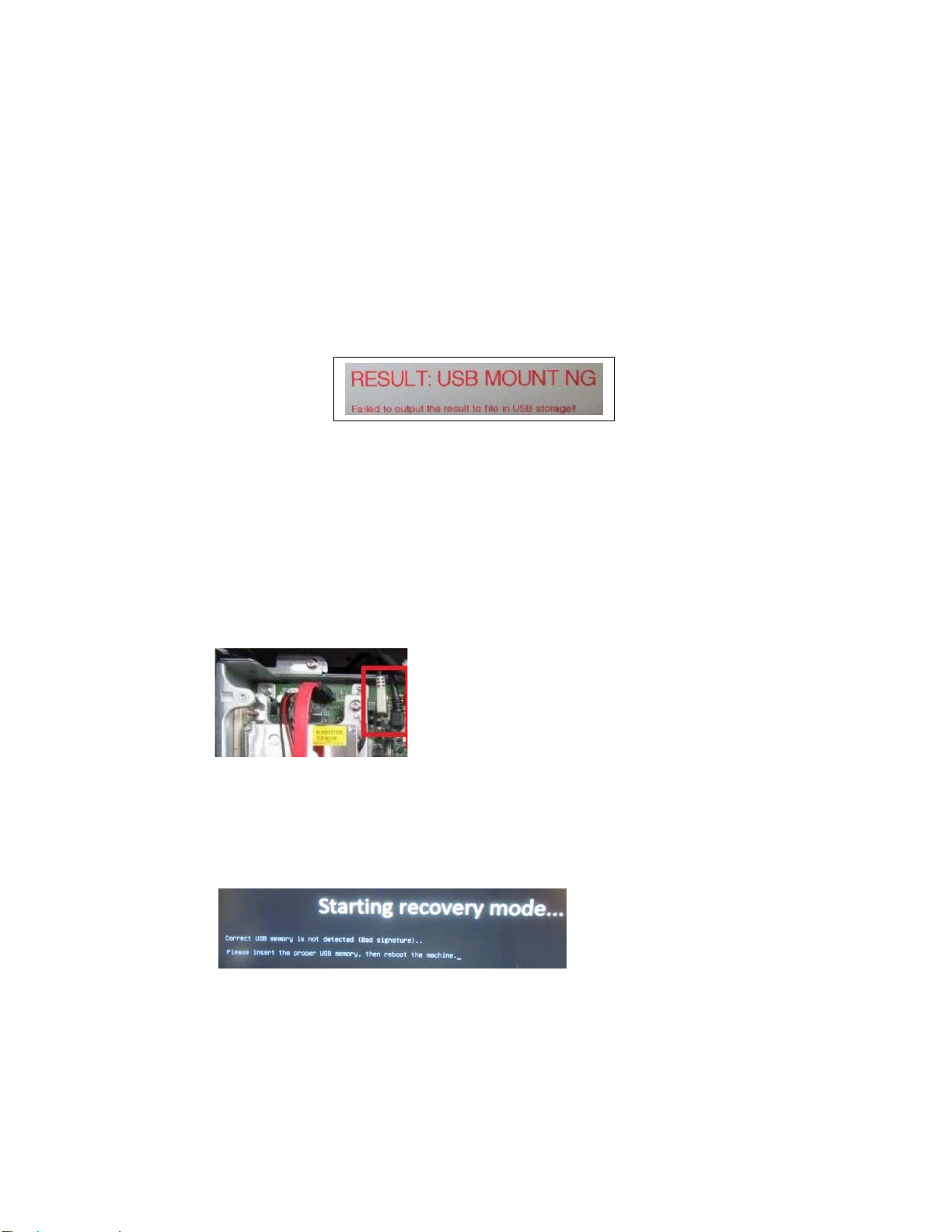
•If "USBMOUNTING: NG" (shown below) should occur when using the Diagnostic tool,
the following can be considered:
oThe USB memory is not formatted in FAT32. Format the USB memory with
FAT32. A USB memory of 32GB or larger in size must be formatted in exFAT.
oA USB hub is connected. Remove the USB hub and connect only the USB
memory that stores the Diagnostic tool.
oA USB connection device other than a USB memory is connected to the main
unit. Connect only the USB memory that stores the Diagnostic tool.
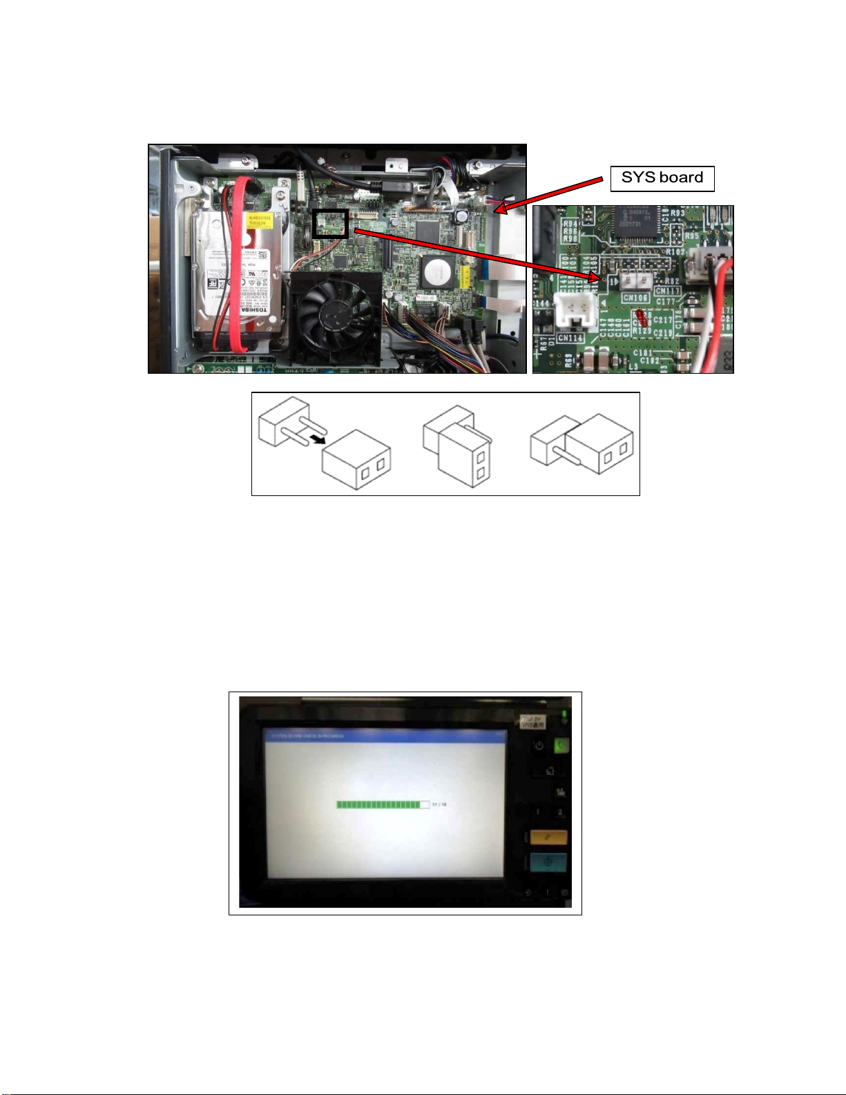
oThe USB harness on the SYS board is not connected properly. Make sure that
the white USB harness connected to the SYS board and the black USB harness
next to it are not connected in reverse (see below).
•If "USBMOUNTING: NG" still occurs even after taking the above measures,
discontinue use and try using a different USB memory device.
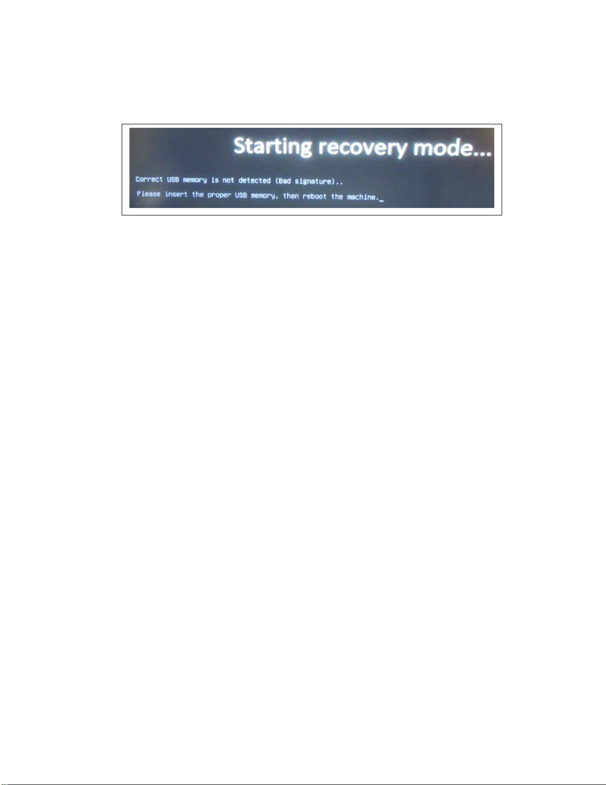
•If the following screen is displayed, save the Diagnostic tool in the USB memory
again and then try again.

4
Introduction
ThismanualdescribestheprocedureforusingtheSYS Board Diagnosis Tool.
This tool inspects the parts function of the SYS board, the communication functions
connecting with other boards, and the HDD function.
The setting values saved in the machine, and the software are not erased.
Do not use this tool for other purposes.
Use this tool when any of the following symptoms has occurred:
•The cause of the call for service is not known and replacing the SYS board is
determined (Conditions of the SYS board are checked).
•The equipment does not start (Control Panel is not displayed)
•A call for service related to the SYS board has occurred.
•A call for service related to the HDD has occurred.
•AN “F” series error has occurred.
Target Models
This tool can only be used on the following models. It does not work properly on any
other models.
•
e-STUDIO2010AC/2510AC
•
e-STUDIO2015C/2515AC/3015AC/3515AC/4515AC/5015AC
•e-STUDIO2018A/2518A/3018A/3518A/4518A/5018A
•
e-STUDIO5516AC/6516AC/7516AC
•
e-STUDIO5518A/6518A/7518A/8518A
USB Memory Requirements
A USB memory must be formatted in FAT 32 and meet the following requirements:
•Capacity 1GB above
•USB 2.0 or higher
Note: A USB memory that is 32GB or larger must be formatted with exFAT.

5
USB Advanced Preparation
Unzip the tool file (ttecbackupflashrom_S18_SYS_Ver01.zip)
and store the tool file under the
root of the USB device as indicated below.
(USB)
┗ttecbackupflashrom
┣bzImage
┣bzImage.sig
┣grub.cfg
┣grub.cfg.sig
┣initrd.gz
┣initrd.gz.sig
┣VerXX *
L jasdat
┣mmr
┣mwp
┣rec
L scan
* XX is the version number.
Note: Do not save the file "SystemRomRecovery" on the same USB.
Procedure to Use the Diagnostic Tool
1. MakesurethattheMainpowerswitchisturnedOFF,andthendisconnectthepower
cable.
2.
Remove the Rear Cover of the MFP.
3. Remove theSYSBoardCover (the screw positions differ depending onthe model).

6
4. Remove the short pin attached to CN106 of the SYS Board and then insert the short
pin on one side of CN106 as shown in the figure below.
5. Insert the USB memory containing the Diagnostic tool into the usb port locate on the
left-side of Control Panel or the upper right side of the machine (the USB memory
insertion slot location differs depending on the model).
6. Insert the power cable into the MFP.
7. Turn on the Main powerswitch ON (all covers must be closed).
8. The following screen with a progress bar will be displayed and the automatic check
process is started.

7
9. When the tool diagnosis has complete, the judgment of OK or NG as shown in the
example figure below is displayed on the LCD of the Control Panel.
10.Whentheresultisdisplayedandthebuzzersounds,pressandholdthepower button for
approximately 5 seconds to turn the power OFF.
Then turn the Main power switch OFF.
11.After confirming that the power is turned OFF, remove the USB memory. The USB will
contain acompressedfilewith testresults saved.
File name:(inspection time)_(machine S/N)_SYS.zip
Example:20200903133800_CNAH00523_SYS.zip
Note: The compressed test result file cannot be accessed with a computer and is for
use by the factory for additional troubleshooting when necessary.
Judgement result
RESULT : NG
HDD Information
V01
V01
HDD Information
V01
V01

8
12.Replace the CN106 short pin removed in Step 4 above to its original position.
Caution: If the CN106 short pin is not returned to its original position, the screen
shown below will be displayed at startup and normal startup will not be possible.
Replace the short pin correctly and restart the machine.
13.Install the removed System Board Cover and Rear cover.
14.End

9
The flow chart below shows the procedure for using the Diagnostic tool.

10
Check Flow A

11
Check Flow B

12
Procedure when the Result is NG
When NG occurs, a screen like the one shown below is displayed on the Control Panel.
1.
Check the item(s) in red.
2.
R
efertotheCorrespondencetable(below) andtakethe correctiveaction.
The inspection number and item results are displayed on the Control Panel. Check the
inspection number and items displayed in red ("NG" and OK?) according to the table below.
Note: If replacement of the SYS board, Main Memory, SRAM (FRAM) and FAN etc. is
required, refer to the replacement procedure in the service manual.
Important Note:
A result of “NG”when using the Diagnostic tool could be caused by reasons other than a
failure of the SYS board such as wiring harness related issues or wire harness connections
to other components.
V01

13
TABLE 1 - Correspondence table when NG occurs
No.
Inspection item
Inspection result
Correspondence
01
Board Type
NG
Replace the SYS board.
02
CPU Clock
NG
Replace the SYS board.
03
FROM
NG
Replace the SYS board.
04
Main Memory
Size
NG
NG <2GB>
NG <4GB>
Step 1.Check the installation status of the
Main
memory and reinstall it if necessary.
Step 2. Perform calibration of the Main
memory at the time of startup.
Step 3.
Replace the Main memory.
Step 4.
Replace the SYS Board.
05
Main Memory
R/W
NG
Step 1. Check the installation status of the
Main memory and reinstall it if necessary.
Step 2. Perform calibration of the Main
memory at the time of startup.
Step 3. Replace the Main memory
Step 4. Replace the SYS board.
06
FRAM R/W
NG
Step 1. Check the installation status of
the SRAM (FRAM) and reinstall it if
necessary.
Step 2. Replace the SRAM (FRAM)
Step 3. Replace the SYS board.
07
RTC
NG
Replace the SYS board.
08
PCIE ASIC0
NG
Replace the SYS board.
09
PCIE ASIC1
OK?
[Not detected]
Check only machine installed the
DSDF unit
Step 1.
Check the installation status of
the DSDF I/F board and reinstall it if
necessary.
Step 2.
Replace the DSDF I/F board.
Step 3.
Replace the SYS board.
10
NIC PCIE
NG [NIC VER]
Step 1.
Update NIC Firmware.
Step 2.
Replace the SYS board.
NG
Replace the SYS board.
11
Network
NG [MAC_I2C]
Replace the SYS board.
NG [MAC_NIC]
Replace the SYS board.
NG [MAC_I2C]
[MAC_NIC]
Replace the SYS board.

14
No.
Inspection item
Inspection result
Correspondence
12
SATA I/F &
SMART
NG [LINK DOWN]
NG [SPD]
Step 1. Check the installation status of
the
HDD harness.
Step 2.
Replace the HDD harness.
Step 3.
Replace the HDD.
Step 4.
Replace the SYS board.
NG [SMART]
Replace the HDD.
NG [ID]
Replace the HDD.
13
USB Host
OK?
Number of USB device connections
(NG will not be displayed)
14
USB Fax
OK?
Number of fax connections
(NG will not be displayed)
OK? [No fax
detected]
15
Scan Control
NG
Replace the SYS board.
16
LGC
Communication
NG
NG [LGC_EN]
NG [C900]
Step 1.
Check the installation status of
CN132 on the SYS board and the
corresponding connector on the LGC
board.
Step 2
. Replace the harness connected
to CN132
Step 3.
Replace the LGC board.
Step 4.
Replace the SYS board.
NG [C963]
Step 1. Check the installation status of
CN131 and CN132 on the SYS board
and the corresponding connector on the
LGC board.
Step 2.
Replace the harness connected
to CN131 and CN132 in sequence
Step 3.
Replace the LGC board.
Step 4.
Replace the SYS board.
NG [LGC_Reset]
Replace the SYS board.
17
SLG
Communication
*1. Here shows the
installed status of
the DF (No
ADF, RADF,
DSDF)
*2. Although it may
be displayed as
"WARMUP", it is
reference
information.
NG<DF*1>*2
Step 1.
Update scanner firmware.
Step 2.
Replace the SYS board.
NG <DF *1>
[SLG_EN] *2
Replace the SYS board.
NG <DF
*
1>
[C260]
*
2
Refer to C260 Troubleshoot of service
manual and check each item.
NG <DF
*
1>
[C261]
*
2
Refer to C261 Troubleshoot of service
manual and check each item.
NG <DF
*
1>
[C262]
*
2
Refer to C262 Troubleshoot of service
manual and check each item.
NG <DF
*
1>
[C270]
*
2
Refer to C270 Troubleshoot of service
manual and check each item.
(Continued on next page)

15
No.
Inspection item
Inspection result
Correspondence
17
NG <DF
*
1>
[C280]
*
2
Refer to C280 Troubleshoot of service
manual and check each item.
NG <DF
*
1>
[C290]
*
2
Step 1.
Check if 24V supplied to the SYS
board.
⇒
If supplied, replace the SYS board.
Step 2
. Check 24V (CN125) and SG on.
Confirm if the SYS board is short circuited
⇒
If shorted, go to
Step 3
⇒
If not shorted, go to Step 4.
Step 3
. Check if the power supply is short
circuited as in Step 2 by pulling
disconnecting the supply harness (CN125)
on the SYS board.
⇒
If shorted, replace the
SYS board
.
⇒
If not shorted, go to Step 4.
Step 4. Check if the fuse
(F203)
on the
LVPS
is open circuited.
⇒
If open, replace the LPVS.
⇒
If not open, go to Step 5.
Step 5.
Check and replace power supply
Harness
Step 6.
Replace LVPS and SYS board in
order.
NG <DF*1>
[C550] *2
Refer to C550 Troubleshoot of service
manual and check each item.
NG <DF*1>
[C551] *2
Refer to C551 Troubleshooting in the
service manual and check each item.
NG <DF*1>
[C552] *2
Refer to C552 Troubleshooting in the
service manual and check each item.
NG <DF*1>
[C553] *2
Refer to C553 Troubleshooting in the service
manual and check each item.
NG <DF*1>
[C554] *2
Refer to C554 Troubleshooting in the service
manual and check each item.
NG <DF*1>
[F110]/[F111] *2
Step 1
. Update scanner firmware.
Step 2
. Replace the SYS board.
NG <DF*1>
[F350] *2
Replace the SYS board.
(Continued on next page)
SLG
Communication
*1.Here shows
the installed
status of the DF
(No
ADF, RADF,
DSDF
)
*2.Although it
may be
displayed as
"WARMUP", it is
reference
information.

16
No.
Inspection item
Inspection result
Correspondence
18
CPU FAN
NG
Step 1. Check if the fan is rotating properly.
⇒
If rotating, replace the SYS board.
⇒
If not rotating, go to Step 2.
Step 2
. Check the FAN connector
(CN117).
⇒
If not improved, go to Step 3.
Step 3
. Replace the following parts in
sequence.
•
FAN
•SYS board
Procedure when the result is OK
Inspection results of optional items such as the USB Host and Fax will not show as
"NG", so check it separately if necessary. Items to be confirmed are displayed as
“OK?” in red. Items marked with "OK" in black have been confirmed and there is not
a problem.
In the case of software related errors such as system firmware and other
software, the judgement result is often displayed as OK. If necessary, perform
HDD format and reinstall the software.
If the inspection result is "OK?", refer to the option connect status in the Table below.
Check the connection status of the option and then troubleshoot if necessary.
V01

17
TABLE 2- Correspondence Table when checking Options
No.
Inspection
Item
Option connect
status
Inspection
result
Correspondence
9
PCIE ASIC1
DSDF
unit connected.
OK
?
(If the DSDF
unit is
connected
properly, result is
"OK")
Step 1. Check the installation
status of the DSDF I/F board.
Step 2. Replace the DSDF IF
board.
Step 3. Replace the SYS
board.
11
NETWORK
LAN connector
connected
OK? [LINK
DOWN]
It is displayed as
below)
"OK[Connect
speed
*]"
*Connect
speed
:
10, 100,
1000Mb/s
Step 1. Check the installation
status of the LAN connector.
Step 2. Check and replace LAN
cable if necessary.
Step 3. Replace the SYS
board.
12
SATA I/F &
SMART
NG [LINK
DOWN]
NG [SPD]
----
If necessary, perform
HDD format and reinstall
the software.
13
USB Host
OK?
Number of USB
device
connections
(NG will not be displayed)
14
USB FAX
Two Fax boards
connected
OK?
[Fax1 detected]
Step 1. Check if connectors
(CN102,CN104) are connected.
Step 2. Check and replace the
connect harness if necessary.
Step 3. Replace the Fax board.
Step 4. Replace the SYS
board.
(
Continued on next page
)

18
No.
Inspection
Item
Option connect
status
Inspection
result
Correspondence
14
USB FAX
Two Fax boards
connected
OK?
[Fax2 detected]
Step 1. Check if connectors
CN101 and CN103 are
connected.
⇒If not improve, go to Step 2.
Step 2.
Check and replace the related
harness.
⇒If not improve, go to Step 3.
Step 3. Replace the Fax board.
⇒If not improve, go to Step 4.
Step 4. Replace the SYS board.
OK? [No Fax
detected]
Since neither fax board could
be detected, check the above
two items.
A Fax board
connected
OK? [No Fax
detected]
Step 1. Check if connectors
CN101 and CN103 are
connected.
⇒If not improve, go to Step 2.
Step 2. Check and replace the
related harness.
⇒If not improve, go to Step 3.
Step 3. Replace the Fax board.
⇒If not improve, go to Step 4
Step 4. Replace the SYS board.

19
Troubleshooting when the tool does not function
When the tool does not function properly, check the following items.
(1) When the USB memory is not recognized, or the file cannot be read.
If the following screen is displayed, confirm the ‘Items to check’below.
Items to check
・Reinsert the USB memory.
・Check the folder name and the file name in the folder.
(Refer to " USB Advanced Preparation" above).
・Re-install the program files on the USB memory.
・Replace the USB memory.
・If there is a "SystemRomRecovery" file directly under the USB memory being
used, remove the file or change the file name.
(2) When the files are corrupted
If the following screen is displayed, re-install the program files on the USB
memory.
Starting recovery mode...
USB memory is not detected. Please insert the proper USB memory,
then reboot the machine

20
(3) When "RESULT : USB MOUNT NG" is displayed on the Control Panel
If the following screen is displayed, confirm the following.
Check if the USB memory mounting position is as shown in the figure below.
Check if the connector mounting position (indicated by the red box) is asshown in
the figure below.
Check if the file systems in the USB memory is formatted in FAT32. If the file system in
the USB memory isn't formatted in FAT32, format the USB memory in FAT32.
(4) When the tool cannot be used
If the tool cannot be used even after performing the above, refer to the service manual.
Other manuals for e-STUDIO2010AC
3
This manual suits for next models
19
Table of contents