Mitchell Diagnostics MD-500 User manual

MD-500 Quick Start Guide
en-US |1
|Quick Start Guide| MD-500
©Mitchell International, Inc. 394474 Rev A | APDMD500020421
1. Front Facing Camera
2. Vehicle Connection Indicator
3. VCI Connection Manager
4. Power Button
5. Volume Up Button
6. Volume Down Button
7. USB C Charging/Data Port
8. Main Menu Functions
9. Back Button
10. Home Button
11. Recent App Button
12. Docking Station Connector
Web Browser
Settings Apps Shortcut
Coverage Guide
i
Video Tutorials
Saved Reports
Diagnostic Information
i
Turbo Scan
Diagnostics
Generic OBDII
Mitchell Connect
mitchell
Explore More
Connected Tuesday 1/12/2021
10:22
Main Menu
1
2
3
11 10 9
45 6 7
12
8
TOP VIEW
BOTTOM VIEW

MD-500 Quick Start Guide
en-US |2
|Quick Start Guide| MD-500
©Mitchell International, Inc. 394474 Rev A | APDMD500020421
Safety Precautions
BEFORE OPERATING THIS TOOL, ALL OPERATORS SHOULD READ
AND UNDERSTAND THIS QUICK START GUIDE AND FOLLOW ALL
SAFETY WARNINGS AND INSTRUCTIONS.
KEEP THESE INSTRUCTIONS WITH THE TOOL FOR FUTURE
REFERENCE. IF YOU HAVE ANY QUESTIONS, CONTACT YOUR
MITCHELL REPRESENTATIVE OR DISTRIBUTOR.
DANGER:
When an engine is operating, keep the service area well ventilated
or attach a building exhaust removal system to the engine exhaust
system. Engines produce carbon monoxide, an odorless, poisonous
gas that causes slower reaction time and can lead to death or serious
personal injury.
WARNING:
• When working with hydraulic or fuel lines, be careful that liquids
under pressure do not escape and create a dangerous condition.
Use adequate ventilation and make sure there are no sparks or
possibility of sparks that may ignite any vapor.
• Wear an American National Standards Institute (ANSI) Z87.1
approved eye shield when testing or repairing vehicles.
• Objects propelled by whirling engine components or pressurized
liquids escaping may cause personal injury.
• Set the parking brake and block the wheels before testing or
repairing a vehicle. It is especially important to block the wheels
on front-wheel drive vehicles because the parking brake does not
hold the drive wheels.
• Do not drive the vehicle and operate the software at the
same time.
• Maintain adequate clearance around moving components or
belts during testing.
• Moving components and belts can catch loose clothing, body
parts, or test equipment and cause serious personal injury or
tool damage.
• Automotive batteries contain sulfuric acid and produce explosive
gases that can result in serious injury due to ignition of gases.
Keep lit cigarettes, sparks, flames, and other ignition sources away
from the battery at all times.
• Refer to the service manual for the vehicle being serviced. Adhere
to all diagnostic procedures and precautions. Failure to do so
could result in personal injury or otherwise unneeded repairs.
• Use only specially designed replacement parts (brake hoses and
lines) for ABS equipped vehicles.
• After bleeding the brake system, check the brake pedal for
excessive travel or a ”spongy” feel. Bleed again if either condition
is present.
• When installing transmitting devices (Citizen Band radio,
telephone, etc) on ABS-equipped vehicles, do not locate the
antenna near the ABS control unit or any other control unit.
• This equipment has been tested and found to comply with the
limits for a Class B digital device, pursuant to Part 15 of the FCC
Rules. These limits are designed to provide reasonable protection
against harmful interference in a residential installation. This
equipment generates and radiates radio frequency energy and,
if not installed and used in accordance with the instructions, may
cause harmful interference to radio communications.
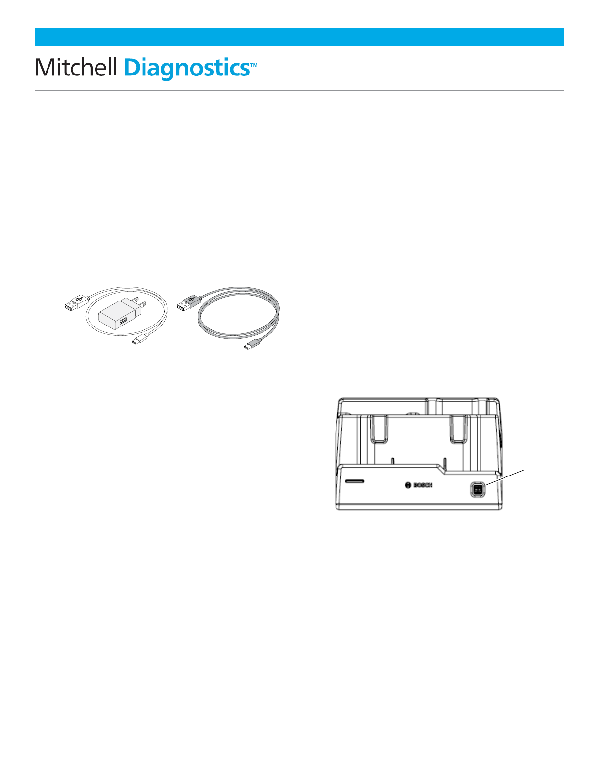
• To reduce risk of injury, charge only Bosch Automotive Service
Solutions, Inc. supplied charging block and power cord.
• Use of an attachment not recommended or sold by the battery
charger manufacturer may result in fire, electric shock, or
personal injury.
• Do not operate the tool with a damaged cord or connector.
Replace damaged cords and connectors immediately.
• Do not operate the charger if it has received a sharp blow, been
dropped, or otherwise damaged in any way. Take the charger to a
qualified service person.
• Do not disassemble the charger. Take the charger to a qualified
service person if service or repair is necessary. Incorrect reassembly
may result in electric shock or fire. Unplug charger before
attempting any maintenance or cleaning. Turning o controls will
not reduce this risk.
• To prevent possible hearing damage, avoid using the tool at high
volume levels for long periods.
• Do not expose tool or charger to rain, moisture, or snow.
• Verify that cords are located where they will not be stepped on,
tripped over, or otherwise become a safety hazard or subjected to
damage or stress.
• Use only batteries that are approved for use with this tool. Use of
other types may increase the risk of fire or explosion.
• Do not carry a battery in your pocket, purse, or other container
where metal objects (such as car keys or paper clips) could short-
circuit the battery terminals. The resulting excessive current flow
can cause extremely high temperatures and may result in damage
to the battery pack or cause fire or burns.
• The battery poses a burn hazard if you handle it improperly. Do
not disassemble it. Handle a damaged or leaking battery with
extreme care. If the battery is damaged, electrolyte may leak from
the cells and may cause personal injury.
• Keep the battery away from children.
• Do not store or leave your tool or battery near a heat source
such as a radiator, fireplace, stove, electric heater, or other heat-
generating appliance or otherwise expose it to temperatures in
excess of 60ºC (140ºF). When heated to excessive temperatures,
battery cells could explode or vent, causing personal injury or risk
of fire.
• Do not dispose of your tool’s battery in a fire or with normal
household waste. Battery cells may explode. Discard a used battery
according to the manufacturer’s instructions or contact your local
waste disposal agency for disposal instructions. Dispose of a spent
or damaged battery promptly.
CAUTION:
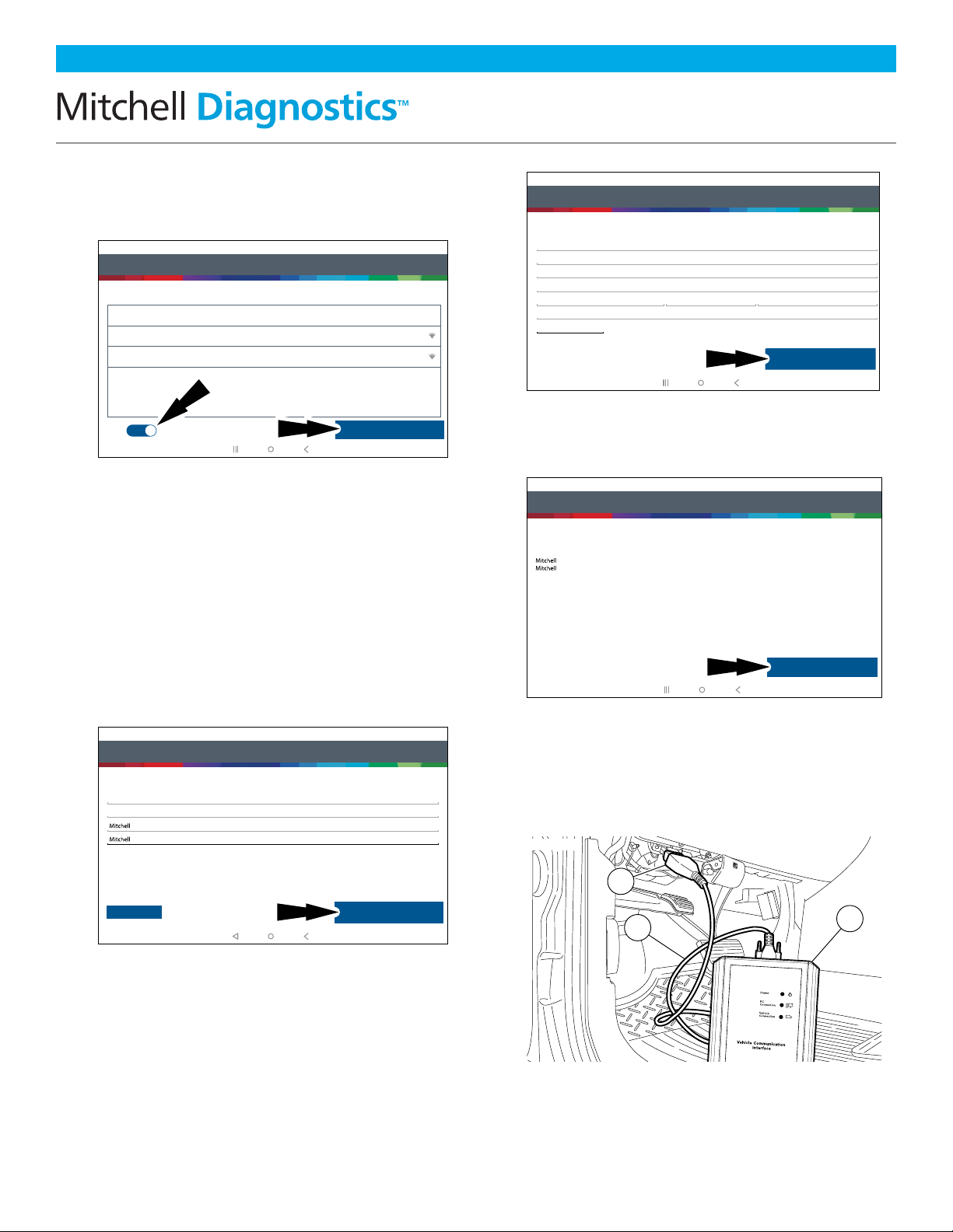
• To avoid damage or generation of false data, make sure the
vehicle battery is fully charged and the connection to the vehicle
Data Link Connector (DLC) is clean and secure.
• Do not place the tool on the distributor of a vehicle. Strong
electromagnetic interference can damage the tool.
• Never disconnect or reconnect any electrical connector while
the ignition is on. Powertrain Control Module (PCM) damage
may result.

MD-500 Quick Start Guide
en-US |3
|Quick Start Guide| MD-500
©Mitchell International, Inc. 394474 Rev A | APDMD500020421
Setup
1. Battery Charging
Connect the tablet to AC power using the USB
power block and USB C charging cord and
fully charge the battery.
When the tablet is turned on, the level of
battery charge is indicated in the upper right
corner of the screen.
Note: MD-500 is supplied with 2 USB C power
cables and 1 USB power block.
Battery Life Tips
The tablet is an Android based touch-screen
tablet. The battery life icon shows charge
level. The scan tool lets you know how much
battery life is left by viewing the icon located
at the top right of the home screen. Like all
Android devices, there are tips to help extend
or maximize battery life.
When not actively being used, the screen
will timeout and the scan tool display will
power off, while application remains running
in background. The user can set the length
of delay between the last screen touch and
automatic screen timeout (dim and lock).
From the Home screen, touch the Android
App button - Settings - Display.
Select Screen timeout, then select the length
of time from the last screen touch and
automatic screen timeout.
To use again, press the power button to wake
the tool up. This will allow maximum run time,
while not limiting productivity.
When the tool is powered up, even if it is not
being actively used, Wi-Fi and Bluetooth®
radios as well as all other necessary
hardware are still being powered. Battery
life is comparable to similar devices when in
this state.
2. Docking Station
The tablet, VCI, and cords should be stored
in the docking station when not in use. The
docking station powers the VCI and provides
a slow, steady charge to the tablet to preserve
battery integrity.
Seat the tablet and VCI in the docking station
so that the docking station connector at
the bottom of each device connects to the
docking station.
The docking station includes two convenient
USB ports to charge accessories and
other devices.
Notes:
• The docking station will not charge the
tablet if the tablet’s USB port is in use.
Ensure no devices are connected to the USB
port on the tablet before connecting to the
docking station.
• For fastest charging, charge the tablet
using the USB power block and USB C
charging cord.
USB
ports
2 ft. cable 6 ft. cable

MD-500 Quick Start Guide
en-US |4
|Quick Start Guide| MD-500
©Mitchell International, Inc. 394474 Rev A | APDMD500020421
3. Press the Power Button to Turn
on the Tablet
Power Button Functions
The power button has four functions:
a. ON: Press and hold the power button for
about 5 seconds to turn the tablet on.
b. OFF: Press and release the power button.
A pop up window will appear to shut
down the tablet. ON: If the screen times
out or is in standby mode, press and
release the power button to wake up
the tablet. Turn ON: With tool off, press
to turn ON.
c. OFF: Press the power button and hold
for 5 seconds to turn the tablet off
completely (not recommended).
4. Register Device—Select a
Language
5. Select Register Now
Register the tool, begin a trial period, or run
the tool in demo mode.
6. Read and Accept the End User
License Agreement
7. Select the Correct Time Zone
Step 1 of 7 - Select as Language
Español
Français
English
rt0002
Step 2 of 7 - Register
Registering your device allows you to get the latest software updates
Skip
Register Now
rt0003
Step 3 of 7 - End User License Agreement
End User License Agreement
Software Product License Agreement
Copyright (c) 2014-2017, Bosch Automotive Service Solutions Inc. All Rights Reserved
By clicking the i Agree button (or authorizing any other person to do so), you accept this Agreement and are
bound by its terms. If you are not sure that you are authorized by your employer to accept this Agreement, take
this package to a principal in your firm before proceeding. This Agreement is a legally binding document setting
forth the menner by which you may use the Bosch Automotive Service Solutions Inc. (”Bosch”) software that is
embedded on the Bosch device and any assoociated media, printed materials and electronic documentation
(collectively “Software Product”) Carefully read the terms and conditions of this Agreement before using this
Software Product. Use of this Software Product indicates your acceptance of the following terms and
conditions.
1. LICENSE. Bosch grants you a personal, non-transferable (except as noted in Section 8 (Assignment)) and
non-exclusive limited license (without the right to sublicense) to ise the Software Product embedded on this
SOFTWARE PRODUCT LICENSE AGREEMENT
Register My Device Now
Register My Device Later
Demo Mode
IMPORTANT: Do not continue until you have read this Software Product License Agreement (”Agreement”).
I Agree
rt0004
Step 4 of 7 - Setup Time Zone
Setup Time Zone
GMT-04:00 Eastern Standard Time
Next: Step Wi-Fi
rt0005

MD-500 Quick Start Guide
en-US |5
|Quick Start Guide| MD-500
©Mitchell International, Inc. 394474 Rev A | APDMD500020421
Enter contact information. Follow the
prompts on the screen.
Confirm information. Follow the prompts on
the screen and activate warranty.
10. Connect the VCI to the Vehicle
1. OBDII/DLC Cable
2. DLC
3. VCI
8. Enable Wi-Fi and Select a
Network and Select Next
Note:
• Wi-Fi Must be ON. If Wi-Fi is OFF slide the
Wi-Fi switch to the ON position and follow
the prompts on the screen.
• If a Network password is required the
Android Wi-Fi screen will be displayed.
Follow the prompts on the screen.
9. Activate Subscription and
Warranty
Enter your Name. Follow the prompts on
the screen to activate warranty.
Step 6 of 7 - Activate Warranty
Activate Subscription and Warranty
Valued
Customer
Bosch
Bosch
Next: Contact info
Set Clock
rt0007
Step 6 of 7 - Activate Warranty
Activate Warranty
ValuedCustomer
123-555-1234
Bosch
Bosch
5/15/2018
5678 Shop Lane
Detroit, Michigan 48260
USA
E0VTOW0000000000GR
Activate Now
rt0009
rt00001
1
2
3
Step 5 of 7 - Select Wi-Fi
Setup Wi-Fi
Secured with WPA
Wi-Fi
TEST 15
TEST 16
Trial Mode
Secured with WPA2
This will run your tool in Trial Mode for 30 days.
Next: Your Name
rt0006
Step 6 of 7 - Activate Warranty
Activate Warranty
123-555-1234
5678 Shop Lane
Detroit Michigan 48260
USA
Address 2 (optional)
Confirm Info
E0VTOW0000000000GR
rt0008

MD-500 Quick Start Guide
en-US |6
|Quick Start Guide| MD-500
©Mitchell International, Inc. 394474 Rev A | APDMD500020421
11. Connect the VCI to the Vehicle
Pairing
The VCI is paired to the tablet during
manufacturing and should be paired out of
the box.
a. Connect the VCI to the vehicle DLC.
b. At this point VCI Connection Manager
icon should display “Connected
via Wi-Fi”.
c. If VCI Connection Manager icon
shows “No connection,” select the VCI
Connection Manager icon.
d. Once VCI Connection Manager
icon is selected, VCI Connection
Manager dialog is displayed, listing
discovered VCIs.
e. Select “Connect” next to VCI in the list to
pair with it.
Once VCI Connection Manager icon
changes to “Connected via Wi-Fi”, the
tool is ready to use.
The tablet is now paired to a VCI. To use a
different VCI in the future, repeat the steps
for manually pairing the VCI.
Select “Connect” next to desired VCI. VCI
Connection Manager dialog will refresh to
show successful connection.
1. Power Port (Used When Necessary)
2. DLC/OBDII Cable Port
3. Power Indicates the VCI Has
Received Power
4. PC Connection Indicates the VCI is
Communicating With the PC
5. Vehicle Connection Indicates the VCI is
Communicating With Vehicle
6. USB “B” Port
7. Docking Station VCI Port
Tuesday 1/12/2021Connected
10:22
Web Browser
Settings Apps Shortcut
Coverage Guide
i
Video Tutorials
Main Menu
Saved Reports
Diagnostic Information
i
Turbo Scan
Diagnostics
Generic OBDII
Mitchell Connect
mitchell
Explore More
rt0011
ss02876
5
6 7
2
1
3
4
VCI Connection Manager Icon Definitions
Icon that will display when user is connected
to DVCI.
Icon will display when user is connected to
DVCI but signal is degraded.
Icon will display when user is NOT connected
to DVCI.
Icon will display when user is connected to
DVCI, but the version does not match expected
tablet version.

MD-500 Quick Start Guide
en-US |7
|Quick Start Guide| MD-500
©Mitchell International, Inc. 394474 Rev A | APDMD500020421
Main Menu
1. Diagnostics
Enter vehicle diagnostics session.
2. Turbo Scan
Shortcut to run an all-system scan.
3. Mitchell Connect
Direct access to the Mitchell Connect
login page.
4. Diagnostic Information
Provides diagnostic, repair and reset
information for the selected vehicle.
5. Generic OBDII
Access Global OBDII emission related
ECU information.
6. Saved Reports
Access saved vehicle scan reports and data
stream recordings.
7. Web Browser
Full internet access and shortcuts to repair
information and OEM websites.
10:22
Main Menu
Tuesday 1/12/2021Connected
Web Browser
Settings Apps Shortcut
Coverage Guide
i
Video Tutorials
Saved Reports
Diagnostic Information
i
Turbo Scan
Diagnostics
Generic OBDII
Mitchell Connect
mitchell
Explore More
rt0012
56
7 8 9
10 11 12
3
4
12
8. Coverage Guide
Access vehicle coverage button.
9. Video Tutorials
Access video tutorial files on scan tool use.
10. Explore More
Mitchell Diagnostics landing page with
add-on products.
11. Settings
Access tool settings, printer setup,
subscription information, software updates
and more.
12. Apps Shortcut
Access other available Android applications.

MD-500 Quick Start Guide
en-US |8
|Quick Start Guide| MD-500
©Mitchell International, Inc. 394474 Rev A | APDMD500020421
Selecting Vehicle
Allows the user to enter a new vehicle or view
Recent Vehicles previously selected. Select the
“Select Vehicle” button then enter a vehicle one
of four ways:
1. Select AutoID to Start to
Automatically Detect the Vehicle
2. Select Manual Selection to
Manually Enter Information
• Year
• Make
• Model
• Engine
3. Select Recent Vehicles to
Select From a List of Previously
Selected Vehicles
4. Enter VIN in Search By VIN Field
AutoID®
• Automatically selects the vehicle using OBD
II Mode 9.
• Identifies vehicles to quickly set up year,
make, model, and engine.
• Coverage: AutoID can be a very fast and
accurate way to select a vehicle. AutoID
retrieves the VIN number from the vehicle’s
on-board computer for OEM’s that support
the function. The function used is Mode
9 Vehicle Information which is one of
the 10 modes of the OBD II regulation.
As illustrated below, Mode 9’s support of
AutoID varies by OEM and model year.
Very few OEM’s support Mode 9 VIN from
1996-2000. Use the information below
to understand when Auto ID is best used.
2000-2004—some US vehicles may respond
to Mode 9 From 2000-2004 it was only used
at the OEMs discretion.
• 2005-2007—many US vehicles will
respond to Mode 9 From 2000-2007 it
was CARB advised, but not required.
• 2008-current—virtually all US vehicles
are required to respond to Mode 9
OBDII Mode 9 was not ARB required
until 2008MY.
10:22
Main Menu
Thursday 1/07/2021Connected
Web Browser
Settings Apps Shortcut
Coverage Guide
i
Video Tutorials
Saved Reports
Diagnostic Information
i
Turbo Scan
Diagnostics
Generic OBDII
Mitchell Connect
mitchell
Explore More
OBDIIOBDIIOBDIIOBDIIOBDIIOBDII
Select Vehicle
Make sure the key is ON and Engine is OFF
Choose vehicle selection method:
SEARCH BY VIN
Cancel
AutoID
Manual Selection
Recent Vehicles
rt0014
10:22
Main Menu
Tuesday 1/12/2021Connected
Web Browser
Settings Apps Shortcut
Coverage Guide
i
Video Tutorials
Saved Reports
Diagnostic Information
i
Turbo Scan
Diagnostics
Generic OBDII
Mitchell Connect
mitchell
Explore More
Select Vehicle
Make sure the key is ON and Engine is OFF
Choose vehicle selection method:
SEARCH BY VIN
Cancel
AutoID
Manual Selection
Recent Vehicles
rt0013
1
2
3
4

MD-500 Quick Start Guide
en-US |9
|Quick Start Guide| MD-500
©Mitchell International, Inc. 394474 Rev A | APDMD500020421
Diagnostic Functions
After selecting a vehicle the user will be
able to begin using diagnostic functions on
the vehicle.
1. Change Vehicle Button
Shortcut to the select vehicle screen.
2. Home Button
Shortcut to the Main Menu.
3. Read DTCs
Access menu to select DTC read options
(all or specific controllers).
4. Data Stream
The data stream function shows live
sensor and solenoid data streaming
from the vehicle ECU (electronic
control unit).
5. All Special Tests
Access Special Test Menu.
6. Special Tests Shortcut
Access to vehicle maintenance tests for
specific vehicle systems to provide for
recalibration or reset after service.
7. Enhanced Vehicle Scan
Access to scan all available controllers
on the selected vehicle for Modes 1—7.
8. Diagnostic Information
Provides diagnostic, repair, and reset
information for the selected vehicle.
9. Wiring Diagrams
Provides OEM and vehicle-specific
full-color, full-system wiring diagrams.
10. Enhanced OBDII
Access manufacturer specific OBDII
parameters and information.
11. Saved Reports
Access saved vehicle scan reports and
data stream recordings.
12. Web Browser
Locate saved vehicle scan reports and
data stream recordings.
13. Apps Shortcut
Access other available
Android applications.
14. Go to ADAS Calibration
Access ADAS systems to perform static
calibrations using MD-TS21.
rt0015
56 7
8 9 10
11 12
14
13
3 4
1 2

MD-500 Quick Start Guide
en-US |10
|Quick Start Guide| MD-500
©Mitchell International, Inc. 394474 Rev A | APDMD500020421
Features
OBDII/DLC Cable
The OBDII/DLC cable has a LED lamp to
locate vehicle DLC and voltmeter that
displays battery voltage.
• The LED in the OBDII cable end is
activated by a button on the side of the
connector. This feature is provided to
assist users in finding the vehicle DLC.
• The vehicle battery indicator is
activated when the OBDII cable is
plugged into the vehicle and displays
the Pin 16 voltage available on the
vehicle DLC. A voltage reading below
11.8 Volts will activate an indication
of “LO” or if above 15.5 Volts and
indication of “HI” will activate
highlighting that the battery or
charging system needs attention.
1. LED Lamp
2. LED lamp Switch
3. Battery Cover
4. DLC Tool Connector With Voltmeter
Software Updates
Software Updates: Periodically, updates
will become available and the user will be
notified through a message on the screen.
To receive updates automatically, connect to
Wi-Fi and leave scan tool on overnight.
Note: Scan Tool will download updates
automatically when connected to the internet.
When download is complete, the user will be
informed with a pop up screen. To install an
update, the scan tool must be connected to the
AC power adapter, over 50% battery life and not
connected to a vehicles DLC.
ss02659
1
2
3
4

MD-500 Quick Start Guide
en-US |11
|Quick Start Guide| MD-500
©Mitchell International, Inc. 394474 Rev A | APDMD500020421
How to Power Off MD-500
a. Press and release the power button.
b. Select Power Off. The tool will
now shutdown.
Note: When switching vehicles, it is best
to return to the home screen before
disconnecting the VCI from the vehicle to
avoid communication errors.
AutoDetect®
The new user interface utilizes graphic
“badges” to illustrate when critical
information is found. AutoDetect®
automatically detects vehicle-specific
solutions and graphically alerts the user of
on-tool or web-based repair information
found. To use the Code To Fix® feature,
press the Diagnostic Trouble Code to
launch the DTC Info screen for access to
exclusive experienced-based fixes and repair
information for that specific vehicle and DTC.
Connected to 2008 Ford F-150 King Ranch 5.4L
Connected
10:22
P0030
Change Vehicle
Heated Oxygen Sensor Heater Control Circuit Sensor 1
Description Description
Mitchell Diagnostics
System Wiring
Measures the amount of oxygen in the exhaust gas and sends a corresponding
signal to the ECM/PCM. The ECM/PCM uses this signal to help maintain an
optimum air/fuel ratio. The sensor has a heating element to allow quicker closed
loop operation.
Code Criteria
Code Assist
Location
Scan Test
PCM Pin
Help
Home
IDENTIFI
FIND AND FIX FASTER
6604
Google
Online Resources
rt0017
Connected to 2008 Ford F-150 King Ranch 5.4L
10:22
Change Vehicle Home
Connected
10:22
Change Vehicle Home
DTC Scan
Change Vehicle
Scan Complete. Tap any item to see error codes
Add Image(s) to Report
PCM / PATS
P0030 - Fail Since Clear - Heated Oxygen Sensor Heater Control Circuit Sensor 1
P0036 - Fail Since Clear - Heated Oxygen Sensor Heater Control Circuit Sensor 2
P0016 - MIL Codes - Crankshaft Position (CKP) -Camshaft Position (CMP) Correlation
INSTRUMENT CLUSTER
4X4 CONTROL
3 DTC(S) found
3 DTC(S) found
3 DTC(S) found
Clear DTCs Refresh Share Save
Home
Details
Details
Details
rt0015
Connected
Generic OBDII Repair-Source
10:22
QuickScan
Apps Shortcut
Settings
What’s New
Web Browser Coverage Guide Video Tutorials
Diagnostic Information Wiring Diagrams
i
i
Saved Reports
Main Menu
Diagnostics
Power off Restart

MD-500 Quick Start Guide
en-US |12
|Quick Start Guide| MD-500
©Mitchell International, Inc. 394474 Rev A | APDMD500020421
Mitchell Technical Support: 800.448.4401
Part No:
Serial No:
Purchase Date:
Please record and retain this important information:
Other manuals for MD-500
2
Table of contents
Other Mitchell Diagnostics Diagnostic Equipment manuals