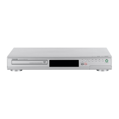
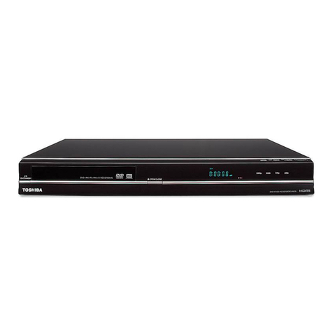
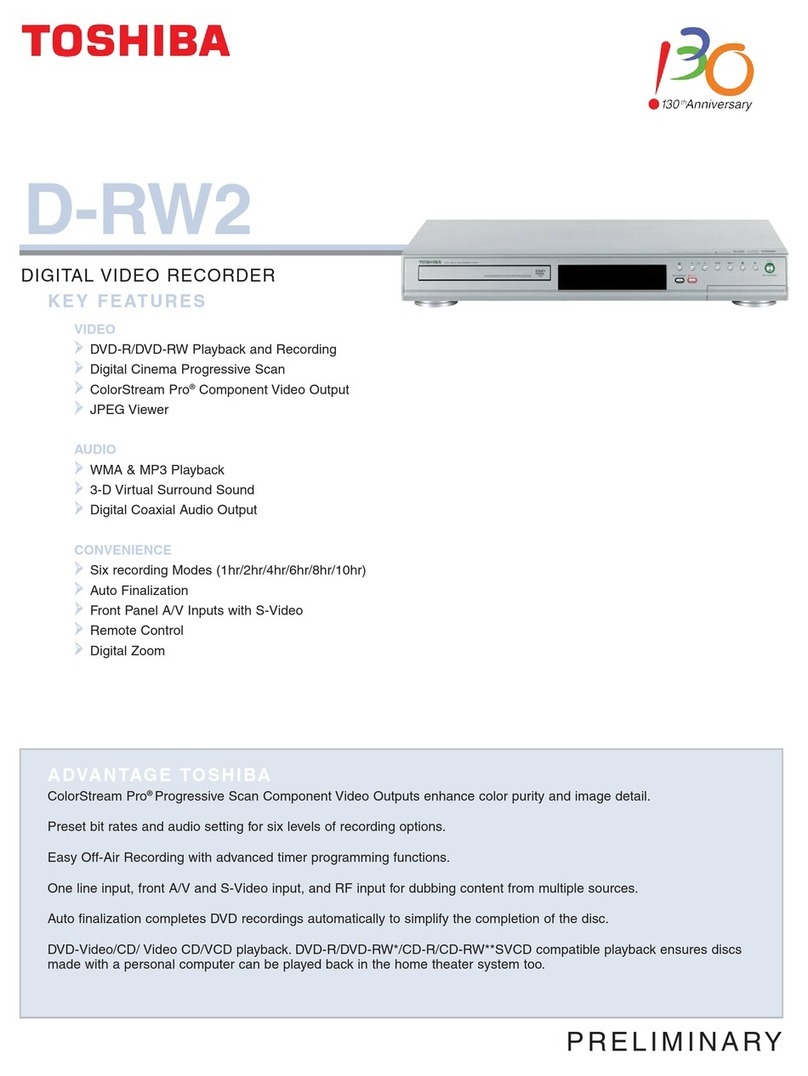
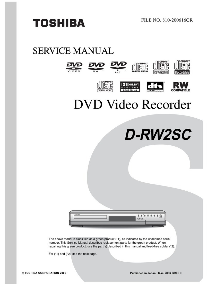
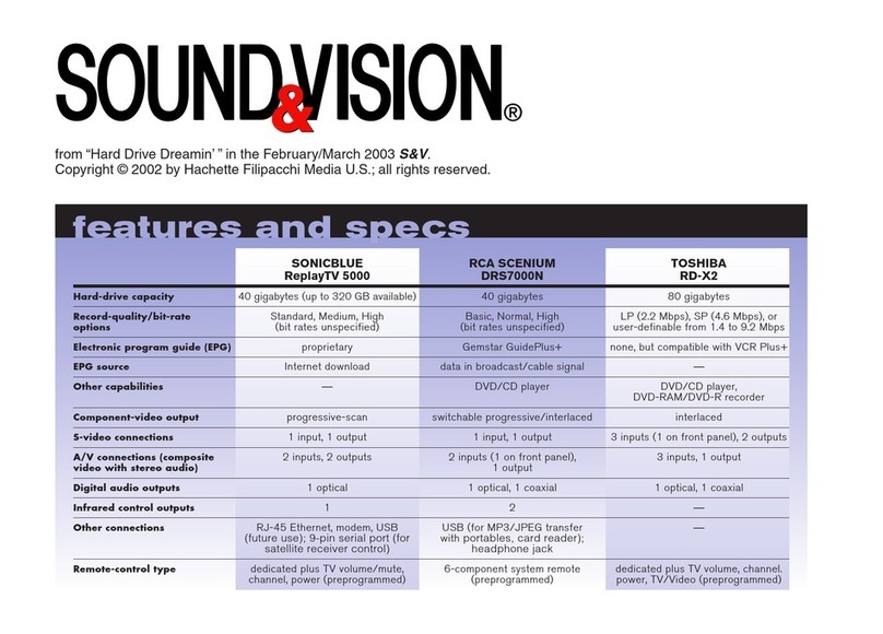
Toshiba D-R350SB User manual

DVD VIDEO RECORDER
SERVICE MANUAL
May, 2005
S
FILE NO. 810-200548
D-R350SB
DIGITAL VIDEO

PREPARATION OF SERVICING
Pickup Head consists of a laser diode that is very susceptible to external static electricity.
Although it operates properly after replacement, if it was subject to electrostatic discharge during replacement,
its life might be shortened. When replacing, use a conductive mat, soldering iron with ground wire, etc. to
protect the laser diode from damage by static electricity.
And also, the SI and IC are same as above.
1M
W
Ground conductive
wrist strap for body.
Soldering iron
with ground wire
or ceramic type
Conductive mat The ground resistance
between the ground line
and the ground is less than 10
W
.
LASER BEAM CAUTION LABEL
When the power supply is being turned on, you may not remove this laser cautions label. If it removes, radiation of a laser
may be received.
·Manufactured under license from Dolby Laboratories. “Dolby” and the double D symbol are trademarks of Dolby
Laboratories.
·“DTS” and “DTS Digital Out” are trademarks of Digital Theater Systems, Inc.
·Manufactured under license from QSound Labs, Inc. U.S. patent Nos. 5,105,462, 5,208,860 and 5,440,638 and various
foreign counterpart. Copyright QSound Labs, Inc. 1998 2002. QXpanderTM is a trademark of QSound Labs, Inc. All
rights reserved.
·VIDEO Plus+ and PlusCode are registered trademarks of Gemstar Development Corporation. The VIDEO Plus+ system
is manufactured under license from Gemstar Development Corporation.

SECTION 2
PART REPLACEMENT AND ADJUSTMENT PROCEDURES
SECTION 3
SERVICING DIAGRAMS
1. CIRCUIT SYMBOLS AND
SUPPLEMENTARY EXPLANATION
1-1. Precau ions for Par Replacemen
1-2. Solid Resis or Indica ion
1-3. Capaci ance Indica ion
1-4. Induc or Indica ion
1-5. Waveform and Vol age Measuremen
1-6. O hers
2. PRINTED WIRING BOARD AND
SCHEMATIC DIAGRAM
3. BLOCK DIAGRAMS
3-1. Overall Block Diagram
4. CIRCUIT DIAGRAMS
4-1. Power Supply Circui Diagram
4-2. Fron Circui Diagram
4-2-1. Fron Jack Circui Diagram
4-2-2. Fron (L) Circui Diagram
4-2-3. Fron (R) Circui Diagram
4-2-4. Fron LED Circui Diagram
4-3. Digi al Circui Diagram
4-4. Mo her Circui Diagram
4-4-1. Tuner In erface Circui Diagram [SH.1]
4-4-2. Audio Circui Diagram [SH.2]
4-4-3. Timer Circui Diagram [SH.3]
4-4-4. Video Circui Diagram [SH.4]
4-4-5. MSP Circui Diagram [SH.5]
5. PC BOARDS
5-1. Power Supply PC Board
5-2. Fron Jack PC Board
5-3. Fron (L) PC Board
5-4. Fron (R) PC Board
5-5. Fron LED PC Board
5-6. Digi al PC Board
5-7. Mo her PC Board
CONTENTS
SECTION 1
GENERAL DESCRIPTIONS
1. OPERATING INSTRUCTIONS
1. REPLACEMENT OF MECHANICAL PARTS
1-1. Cabine Replacemen
1-1-1. Top Cover
1-1-2. Fron Panel
1-1-3. RAM Drive
1-1-4. Rear Panel
1-1-5. Fan
1-2. PC Board Replacemen
1-2-1. Digi al PC Board
1-2-2. Mo her PC Board
1-2-3. Power PC Board
1-2-4. Fron (R), Fron (L), Fron (LED),
Fron Jack PC Boards
2. WIRING CONNECTION DIAGRAM
2. LOCATION OF MAIN PARTS
2-1. Loca ion of Main Par s
2-2. Loca ion of PC Boards
SECTION 4
PARTS LIST
SAFETY PRECAUTION
NOTICE
ABBREVIATIONS
1. EXPLODED VIEWS
1-1. Packing Assembly
1-2. Chassis Assembly
2. PARTS LIST

SECTION 1
GENERAL DESCRIPTIONS
1. OPERATING INSTRUCTIONS
Please refer to the owner's manual about the contents.
SECTION 1
GENERAL DESCRIPTIONS

2. LOCATION OF MAIN PARTS
2-1. Location of Main Parts
Fig. 1-2-1
2-2. Location of PC Boards
Fig. 1-2-2
ZG45 FAN
RAM1 RAM DRIVE
EU02 Power PC board
EU05 Mother PC board
EU01 Digital PC board
EU03A Front (R) PC board
EU55 Front Jack PC board
EU03B Front (L)
PC board
EU56 Front (LED)
PC board

1-1. Cabinet Replacement
1-1-1. Top Cover
1. Remove seven screws (1), then remove the top cover (2).
Fig. 2-1-1
SECTION 2
PART REPLACEMENT AND
ADJUSTMENT PROCEDURES
Screws (1)
Screws (1)
Screws (1)
Top cover (2)
SECTION 2
PART REPLACEMENT AND
ADJUSTMENT PROCEDURES
CAUTIONS BEFORE STARTING PART REPLACEMENT
Electronic parts are susceptible to static electricity and may easily damaged, so do not forget to ground as required.
any screws are used inside the unit. To prevent the screws from missing or dropping, etc. always use a magnetized
screwdriver in servicing. Several kinds of screws are used and some of them need special cautions. That is, take care of
the tapping screws securing molded parts and fine pitch screws used to secure metal parts. If they are used improperly,
the screw holes will be easily damaged and the parts can not be fixed.
1. REPLACEMENT OF MECHANICAL PARTS

1-1-2. Front Panel
1. Remove the top cover. (Refer to item 1-1-1.)
2. Remove the Digital PC board. (Refer to item 1-2-1.)
3. Disconnect three connectors (1).
4. Remove t o scre s (2) and four cla s, then remove the front panel (3).
Fig. 2-1-2
1-1-3. RAM Drive
1. Remove the front panel. (Refer to item 1-1-2.)
2. Peel off the tape (1).
3. Disconnect the flexible cable (2) and connector (3).
4. Remove three scre s (4) and three scre s (5), then remove the RAM drive (6).
5. Remove the shield cover (7).
Note:
• After replacing, attach the tape (1) to its original position.
Fig. 2-1-3
Connector (1)
Connector (1)
Connector (1)
Screws (2)
Front panel (3)
Claw
Claw
Claws
Flexible
cable (2)
Connector (3)
Tape (1)
Screws (4)
Screws (5)
RAM drive (6)
Shield cover (7)

1-1-4. Rear Panel
1. Remove the top cover. (Refer to item 1-1-1.)
2. Peel of the tape (1).
3. Remove two screws (2) and seven screws (3).
4. Remove two claws, then remove the rear panel (4).
5. Remove two screws (5), then remove the fan (6).
Note:
After replacing, attach the tape (1) to its original position.
Fig. 2-1-4
1-1-5. Fan
1. Remove the top cover. (Refer to item 1-1-1.)
2. Peel off the tape (1).
3. Disconnect the connector (2).
4. Remove two screws (3), then remove the fan (4).
Note:
After replacing, attach the tape (1) to its original position.
Screws (2)
Screws (3)
Screws (5)
Fan (6)
Tape (1)
Rear pane (4)
C aw
C aw
Screws (3)
Connector (2)
Fan (4)
Tape (1)
Hexagona
nuts
Fig. 2-1-5

1-2. PC Board Replacement
1-2-1. Digital PC Board
1. Remove the top cover. (Refer to item 1-1-1.)
2. Disconnect the flexible cable (1).
3. Remove four screws (2), then remove the Digital C board (3).
Note:
• The Digital C board (3) is connected to the Mother C board (4) by three connectors (5). Take notice when removing.
Fig. 2-1-6
Screws (2)
Digita PC
board (3)
F exib e
cab e (1)
F exib e
cab e (1)
Connector
C aw
Connector (5) Connectors (5)
Mother PC board (4)
Remove the connector c aw
in the direction indicated
by the arrows to re ease the
f exib e cab e.

1-2-2. Mother PC Board
1. Remove the rear panel. (Refer to item 1-1-4.)
2. Remove the Digital PC board. (Refer to item 1-2-1.)
3. Disconnect three connectors (1).
4. Remove five scre s (2) .
5. Pull out the Mother PC board (3) to ard the rear side (indicated by the arro ).
Fig. 2-1-7
Screws (2)
Mother PC
board (3)
Connectors (1) Connector (1)

1-2-3. Power PC Board
1. Remove the RAM drive. (Refer to item 1-1-3.)
2. Disconnect four connectors (1).
3. Remove four screws (2), then remove the Power PC bo rd (3).
Fig. 2-1-8
Connector (1)
Connector (1)
Connectors (1)
Power
PC board (3)
Screws (2)

1-2-4. Front (R), Front (L), Front (LED) and Front Jack PC Boards
1. Remove the front panel. (Refer to item 1-1-2.)
2. Peel off the tape (1).
3. Remove four screws (2), then remove the stay (3).
4. Remove four screws (4) and two screws ( ), then remove the Front (R) PC board (6) and Front (LED) PC board (7).
. Remove two screws (8), then remove the Front Jack PC board (9).
6. Remove four screws (10), then remove the Front (L) PC board (11).
Note:
• After replacing, attach the tape (1) to its original position.
Fig. 2-1-9
Screws (2)
Screws (8)
Screws (4)
Screws (5)
Screws (10)
Front (LED)
PC board (7)
Stay (3)
Front (L) PC board (11)
Front (R) PC board (6)
Tape (1)
Front Jack
PC board (9)
Front panel
Stay Front (L) PC boardTray doorWire
Front (R) PC board Front Jack
PC board
Fasten with the tape.
Front (LED)
PC board
Note:
• Fasten with the tape, taking care so that the wire does not hang over the tray door.
Fig. 2-1-10

: Flexible cable
: Tape
Front panel
RAM drive W801
Power PC board
Mother PC board
Digital PC board
Fan
W051
W101 W104
W102
2. WIRING CONNECTION DIAGRAM
After the servicing is complete, return the wiring to its original state by using the diagram below as a reference.
Fig. 2-2-1

1. CIRCUIT SYMBOLS AND SUPPLEMENTARY EXPLANATION
1-1. Precautions for Part Replacement
• In the schematic diagram, parts marked (ex.
F801) are critical part to meet the safety regulations,
so al ays use the parts bearing specified part codes
(SN) hen replacing them.
1-2. Solid Resistor Indication
Unit None ........... W
K ........... kW
M ........... MW
Tolerance None ........... ±5%
B ........... ±0.1%
C ........... ±0.25%
D ........... ±0.5%
F ........... ±1%
G ........... ±2%
K ........... ±10%
M ........... ±20%
Rated Wattage (1) Chip Parts
None ......... 1/1 W
(2) Other Parts
None ......... 1/ W
Other than above, described in the Circuit Diagram.
Type None ........... Carbon film
S ........... Solid
R ........... Oxide metal film
M ........... Metal film
W ........... Cement
FR ........... Fusible
Symbol
+
........... Electrolytic, Special electrolytic
NP
........... Non polarity electrolytic
........... Ceramic, plastic
M........... Film
........... Trimmer
Unit None ........... F
m........... mF
p ........... pF
Rated voltage None ........... 50V
For other than 50V and electrolytic capacitors,
described in the Circuit Diagram.
Tolerance (1) Ceramic, plastic, and film capacitors of which
capacitance are more than 10 pF.
None ........... ±5% or more
B ........... ±0.1%
C ........... ±0.25%
D ........... ±0.5%
F ........... ±1%
G ........... ±2%
(2) Ceramic, plastic, and film capacitors of which
capacitance are 10 pF or less.
None ........... more than ±5 pF
B ........... ±0.1 pF
C ........... ±0.25 pF
(3) Electrolytic, Trimmer
Tolerance is not described.
Temperature characteristic None ........... SL
(Ceramic capacitor) For others, temperature characteristics are
described. (For capacitors of 0.01 mF and
no indications are described as F.)
Static electricity capacity Sometimes described with abbreviated letters as
(Ceramic capacitor) shown in Eg. 3.
1-3. Capacitance Indication
100k
Rated Wattage Type Tolerance
Eg. 1
104
10x104pF (0.1
m
F)
Temperature characteristic
(or Temperature characteristic+
Static electricity capacity tolerance)
Eg. 3
100
m
Temperature
response Rated
voltage Tolerance
Eg. 2
Fig. 3-1-1
Fig. 3-1-3
Fig. 3-1-2
• Using the parts other than those specified shall violate
the regulations, and may cause troubles such as
operation failures, fire etc.
SECTION 3
SERVICING DIAGRAMS
SECTION 3
SERVICIN DIA RAMS

1-4. Inductor Indication
Unit None ........... H
m........... mH
m ........... mH
Tolerance None ........... ±5%
B ........... ±0.1%
C ........... ±0.25%
D ........... ±0.5%
F ........... ±1%
G ........... ±2%
K ........... ±10%
M ........... ±20%
1-5. Waveform and Voltage Measurement
• The waveforms for CD/DVD and RF shown in the
circuit diagrams are obtained when a test disc is
played back
• All voltage values except the waveforms are expressed
in DC and measured by a digital voltmeter
1-6. Others
• The parts indicated with "NC" or "KETU" etc are not
used in the circuits of this model
Eg. 4
Eg. 5
Fig. 3-1-4
Fig. 3-1-5
Type name
10
m
Type Tolerance

2. PRINTED WIRING BOARD AND SCHEMATIC DIAGRAM
Fig. 3-2-1
1
2
3
4
5
3
2
1
3
2
1
6
5
4
3
2
1
6
5
4
3
2
1
1
2
3
4
5
6
7
8
11
10
9
8
7
6
5
4
3
2
1
1
2
3
4
5
6
7
8
11
10
9
8
7
6
5
4
3
2
1
10
9
8
7
6
5
4
3
2
1
CN701
23 23
22 22
521
420
319
218
117
21
20
19
18
17
16 16
15 15
14 14
13 13
12 12
11 11
10
9
8
7
6
5
4
3
2
1
10
9
8
7
6
5
4
3
2
1
14
13
12
11
10
9
8
7
6
5
4
3
2
1
26
25
24
23
22
21
20
19
18
17
16
15
14
13
12
11
10
9
8
7
6
5
4
3
2
1
14
13
12
11
10
9
8
7
6
5
4
3
2
1
14
13
12
11
10
9
8
7
6
5
4
3
2
1
26
25
24
23
22
21
20
19
18
17
16
15
14
13
12
11
10
9
8
7
6
5
4
3
2
1
14
13
12
11
10
9
8
7
6
5
4
3
2
1
1
2
3
4
5
6
7
8
1
2
3
4
5
6
7
8
1
2
3
4
5
6
1
2
3
4
1
2
1
2
3
4
5
6
7
8
9
10
11
12
13
14
15
16
17
18
19
20
21
22
23
24
25
26
27
28
29
30
31
32
33
34
35
36
37
38
39
40
1
2
3
4
5
6
7
8
9
10
11
12
13
14
15
16
17
18
19
20
21
22
23
24
25
26
27
28
29
30
31
32
33
34
35
36
37
38
39
40
1
2
3
4
5
6
CN710
CN101
GND
POWER_ON1
GND
ON/OFF +3.3V
GND
POWER_ON1
GND
ON/OFF +3.3V
GND
GND
ON/OFF8V
ON/OFF +3.3V
GND
ON/OFF +1.5V
GND
ON/OFF +5V
GND
ON/OFF +3.3V
VIDEO_Y
GND
VIDEO_COMP
AUDIO_L
GND
LED1
LED2
GND
VIDEO_C
DRIVER_SCK
GND
DRIVER (T-D)
W104
RMT
KEY2
RMT
W105AW105
RMT
FL+5V
LED1
LED2
W103AW103
FL+5V
GND
DRIVER_SCK
DRIVER_CS
DRIVER (D-T)
CN708
GND
ON/OFF +32V
GND
D+3.3V
CPU5V
ON/OFF +12V
GND
VKK
PB-DATA
A-GND
PB-LRCK
V-GND
V-GND
SPICS
V-GND
REC-ACK
PB-BCK
A-GND
A-GND
B_DD15
B_DD1
B_DD14
B-B
NC
D_GND
B_CS1
B_CS0
B_CS2
B_DMAREQ
B_DD12
B_DD2
B_DD13
GND
D+1.5V
B_DA0
EMA-SIG-DET
SPICK
IEC958
B_DA1
NC
B_INTRQ
NC
D_GND
B_IORDY
GND
B_DD9
FL(+)
FL(-)
VKK-31V
W102
GND
POWER_ON0
POWER GOOD
EVER +5V
CN104
CN307
B_DD8
B_DD6
+5V
B_DRESET
CN104-1
B_DD7
+5V
D_GND
CN105
A-GND D_GND
IEC958
D_GND
B_DIOW
PB-LRCK
A-GND
EMA-SIG-DET
PB-DATA
FL+5V
PB-ACK
CNW01
GND
GND
GND
GND
D+1.5V
D+1.5V
GND
B_DMACK
D_GND
B_DIOR
C-OUT
CR-OUT
A-GND
SPIDA
V-GND
SPICS
V-GND
CY-OUT
SPICK
B_DD3
B_DD5
B_DD10
B_DD4
B_DD11
PB-BCK
NC
D_GND
A-GND
D+1.5V
GND
VKK-31V
D+1.5V
D+5V
D+3.3V
GND
GND
D+3.3V
+12V
ON/OFF +1.5V
GND
GND
EVER12V
ON/OFF +32V
ON/OFF +12V
GND
EVER +6V
VKK
+12V
+12V
GND
GND
GND
DD6
GND
D+1.5V
D+3.3V
DD9
B-B
GND
GND
D+5V
FL+5V
FL(-)
FL(+)
GND
DD1
DD14
DD5
DD4
DD10
DD13
DD11
DD3
DD2
DD12
DD0
DD15
GND
B_DD0
D_GND
POWER GOOD
POWER_ON0
GND
+5V
FAN +12V
FAN GND
CPU5V
EVER +5V
GND
+12V
+12V
EVER12V
CN102
GND
GND
+5V
+5V
EVER +6V
RESETX
GND
DD7
DD8
Reserved
DMARQ
GND
DIOW
GND
DIOR
GND
DA1
PDIAG
IORDY
CSEL
DMACK
GND
INTRQ
NC
DASP
GND
DA0
DA2
CS0
CS1
V-GND
CN702
AUDIO_R
-/SC
RXD(R-T)
V-GND
D-GND
KEY2
TPI-
GND
TPI+
GND
GND
GND
TXD2
GND
RTS2
RXD2
CN305
D3.3V
FLSSHW-X
CTS2
REC_LRCK
REC_DATA
C-OUT
V-GND
V-GND
CB-OUT
V-GND
V-GND
CR-OUT
Y-OUT
-/SC
CN901
B-B
GND
CV/SY
CN201
TPO+
TPO-
D-GND
REC_BCK
REC_LRCK
REC_BCK
TXD(T-R)
CN301
TXD(T-R)
CTS(R-T)
V-GND
RTS(T-R)
V-GND
CTS(R-T)
V-GND
CN703
DRIVER (T-D)
DRIVER (D-T)
V-GND
KEY1
W101
AUDIO_R
HIZ
AUDIO_L
L-GND
GND
2S_SW
GND
GND
GND
RXD_OUT
GND
VIDEO_Y
VIDEO_COMP
GND
GND
2S_SW
VIDEO_C
RMT
D-GND
A-GND
CN308
DRIVER_SCK
GND
U/V_VIDEO
RTS(T-R)
CN302
REC-ACK
PB-ACK
U/V_VIDEO
RXD(R-T)
KEY1
ON/OFF +5V
A-GND
Y-OUT
V-GND
SPIDA
CY-OUT
CB-OUT
GND
PDC_ON/OFF
ON/OFF8V
DRIVER_CS
DRIVER (D-T)
DRIVER (T-D)
PDC_ON/OFF
DRIVER (T-D)
DRIVER (D-T)
DRIVER_CS
A-GND
-
GND
DRIVER_CS
DRIVER_SCK
REC_DATA
CV/SY
D-GND
TXD_OUT
-
L-GND
WRITE_ENABLE
TIMER_RESET
CPU+5V
W051
FAN
LEADS
CABLE memo
W101 LEADS CABLE 11 175
W102 LEADS CABLE 05 280
W103 PARALLEL CABLE 06
W104 LEADS CABLE 08 175
W105 PARALLEL CABLE 06
W701 LEADS CABLE 15 250
W801 LEADS CABLE 06 180
LEADS
CABLE
RAM DRIVE
W102
W801
EU03A
FRONT (R)
EU03B
FRONT (L)
232C
Timer F/W WRITE
FFC
TCSN9082PA20T (TUNER)
MB01
LAN
TUNER
TOSHIBA DRIVE
PARALLEL
LEADS
CABLE
EU56
FRONT LED
PARALLEL
W105
W103
W104 W101
W701
LEADS
CABLE
LEADS
CABLE
memo
W051 FFC 40 290
WB01 FFC 11 90
W701 EU05 MOTHER
EU02
POWER
EU01 DIGITAL
EU55
FRONT JACK
RAM1

Fig. 3-5-14 EU05 Mother PC Board (Bottom side)
FM6
C700
C701
C703
C704
C705
C706
C707
C708
C709
C711
C712
C713
C714
C715
C716
C717
C722
C750
C752
C755
C759
C761
C902 C903
C905
C911
C925
CA07
CA08 CA09
CB08
CB10
CB12
CB13
CB14
CB15
CM01
CM03
CM04
CM06
CM07
CM13
CM15
CM16
CM17
CM19CM20
CM21
CM22
CM23 CM25
CM27
CM28 CM29
CM30
CW01
CW21
CW22 CW23CW24 CW25CW26 CW27CW28 CW30
CW37
CW40 CW41 CW42 CW43
CX03
CX19
CX20
CX40
CX41
CX47
CX50
CX51
CX52
CX53
CX54
CX55
CX57
CX59
CX64
CX66
CX67
CX73
CX75
CX76
CX79
CX81
CX86
D701
DM01
DW05
DW06
DW09 DW10
DW11 DW12
DW13
DW19
DW33
DX04 DX05
DX06
DX07
DX08 DX09
IC700
IC701
IC906
ICM01
ICM02
L701
L706
LB11
LB12
LM04
LM05
LM06
Q901
QB02
QB04
QX01
R700
R701
R702
R703
R704
R705
R706
R707
R708 R709
R711
R718
R721
R722
R723
R726
R727
R728
R729
R731
R733
R734
R735
R736
R737
R740
R741
R742
R743
R744
R745
R747
R759
R760
R761
R763
R774
R775
R780
R781
R782
R783
R784
R786
R787
R788
R790
R791
R792
R797
R798
R901
R907 R908
R912
R913
R915
R920 R923
R925 R931
R933R934
R944R945
R951
R952
R953
R954
R955
R956
R957
R960
RA01
RA14
RA15
RB03
RB05 RB14
RB15
RB16
RB17
RB18
RB20
RB21
RB22
RB23
RB24
RB25
RM01
RM02
RM03
RM04
RM07
RW03
RW04
RW05
RW06
RW07
RW08
RW09
RW10
RW11
RW12RW14RW21RW22RW27
RW31
RW36 RW60 RW61 RW62 RW63
RW72RW73 RW74RW75 RW76
RW77 RW78RW79
RX10
RX12
RX17
RX18
RX19
RX20
RX21
RX31
RX32 RX33
RX34
RX35
RX36
RX40
RX41
RX42
RX43
RX44
RX45
RX46
RX47
RX51
X701
123456
A
B
C
D
E
F

SECTION 4
PARTS LIST
SAFETY PRECAUTION
The parts identified by ! ( ) mark are critical for safety. Replace only with part number specified.
The mounting position of replacement is to be identical with originals.
The substitute replacement parts which do not have the same safety characteristics as specified in the parts list may create
shock, fire or other hazards.
NOTICE
The part number must be used when ordering parts in order to assist in processing, be sure to include the model number and
description.
ABBREVIATIONS
• Integrated Circuit (IC)
• Capacitor (Cap)
• Capacitance Tolerance (for Nominal Capacitance more than 10pF)
P
100
0
Symbol
Tolerance %
B
± 0.1
C
± 0.25
D
± 0.5
F
± 1
G
± 2
± 5
K
± 10
M
± 20
N
± 30
V
20
– 10
W
100
– 10
U
75
– 10
Q
30
– 10
T
50
– 10
Symbol
Tolerance %
X
40
– 20
Y
150
– 10
Z
80
– 20
Ex. 10MF J = 10µF ± 5%
Symbol
Tolerance pF
B
± 0.1
C
± 0.25
D
± 0.5
F
± 1
G
± 2
Ex. 10pF G = 10pF ± 2pF
M
± 20
Symbol
Tolerance %
B
± 0.1
C
± 0.25
D
± 0.5
F
± 1
G
± 2
± 5
K
± 10
Ex. 470 ohm J = 470 ohm ± 5%
Table 4-2-1
Table 4-2-2
Table 4-3-1
• Capacitance Tolerance (for Nominal Capacitance 10pF or less)
• Resistor (Res)
• Resistance tolerance
SECTION 4
PARTS LIST

1. EXPLODED VIEWS
1-1. Packing Assembly
Fig. 4-1-1
Z001A
Z001
Note: The shape of the packing
material is sometimes different.
Z002
Z031
Z032
Z033
Power supply cable
(Z001)
Clamp filter
(Z001A)
Fixed band
(accessories)
Note:
A clamp filter (Z001A) is attached to a power cord (Z001).
Refer to the figure below for the installation.
Turn the power supply cable
2 round in the clamp filter.
Cut the portion in which
the fixed band remained.

1-2. Chassis Assembly
Fig. 4-1-2
EU55
EU03B
EU56
EU03A
ZG01
W051 RAM1
ZG45
EU01
EU05
EU02
ZG20
Table of contents
Other Toshiba DVR manuals

Toshiba
Toshiba D-RW2SU User manual
Toshiba
Toshiba D-R1SU User manual

Toshiba
Toshiba RD-XS52SU User manual

Toshiba
Toshiba RD-XS32SU User manual

Toshiba
Toshiba D-R2S User manual

Toshiba
Toshiba RD-85DTSB User manual

Toshiba
Toshiba D-KVR20KU User manual

Toshiba
Toshiba NVSe User manual

Toshiba
Toshiba D-R4 User manual

Toshiba
Toshiba RD-XS32SB User manual

Toshiba
Toshiba D-R410KU User manual

Toshiba
Toshiba RD-XS24SB User manual

Toshiba
Toshiba D-R150SB User manual

Toshiba
Toshiba RD-X2 User manual

Toshiba
Toshiba HDR5010KB User manual

Toshiba
Toshiba RD-85DTSB User manual

Toshiba
Toshiba RD-XS54SU User manual

Toshiba
Toshiba SURVEILLIX IPS8-X User manual

Toshiba
Toshiba D-R2SU User manual

Toshiba
Toshiba D-R4SU User manual