13/15
4.1 Test
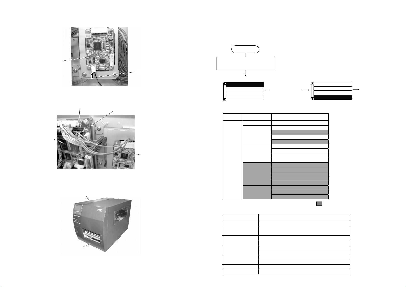
(1) ID READ
The printer enters the read test mode to read the data of the RFID tag, and a read test is
performed each time the [ENTER] key is pressed. When the data of a tag can be read,
they are displayed on the LCD.
(Example)
▪Only the tags selected for the RFID tag type can be read. If the type of the tag to be
read does not match the one selected in the RFID tag type, an error will occur.
Therefore, the RFID tag type shall be selected before the read test is started.
▪When the read test has failed, the following message is displayed on the LCD:
Error message Description
MODULE TYPE ERROR RFID module type has been set to NONE or a communication
cannot be established.
COUNTRY CONFIG ERROR Country/Region code has not been set.
READ ERROR
Confirm Setting or Set other Tag The type of the tag to be read and one selected by the RFID
tag type selection do not match.
NOT AVAILABLE Not supported.
NO RESPONSE No response from the tag
READ TIMEOUT
Set a RF-Tag on Ant. Timeout
UNKNOWN ERROR Other errors
▪In the case of 32 digits or more data, only the first 32 digits are displayed. When the
data are less than 32 digits, the vacant digits will be filled with spaces.
▪If more than one tag is read at one time, especially when short-pitch tags are used,
pressing the [UP] or [DOWN] key shows the other tags’ data.
4.2 Module
(1) MODULE TYPE
NONE: No RFID module is installed.
H1: B-EX700-RFID-H1-QM-R
H2: B-EX700-RFID-H2-R, B-EX700-RFID-H3-QM-R
U2: B-EX700-RFID-U2-US/EU-R, B-EX700-RFID-U4-US/EU-R, U4 module
preinstall model
(B-EX4T1/EX4T2-GS18/TS18-CN-R)
Tip: This setting will become effective after the printer power is turned off and then back on.
(2) COUNTRY
This is not available. Do not use this module.
ID READ
TAG
1/1
00010203 04050607
The number of the tag is being read / The total number of tags
The data of the read tag are displayed in hex.
14/15
(3) TAG
None
ISO15693
(4) CHANNEL
This is not available. Do not use this module.
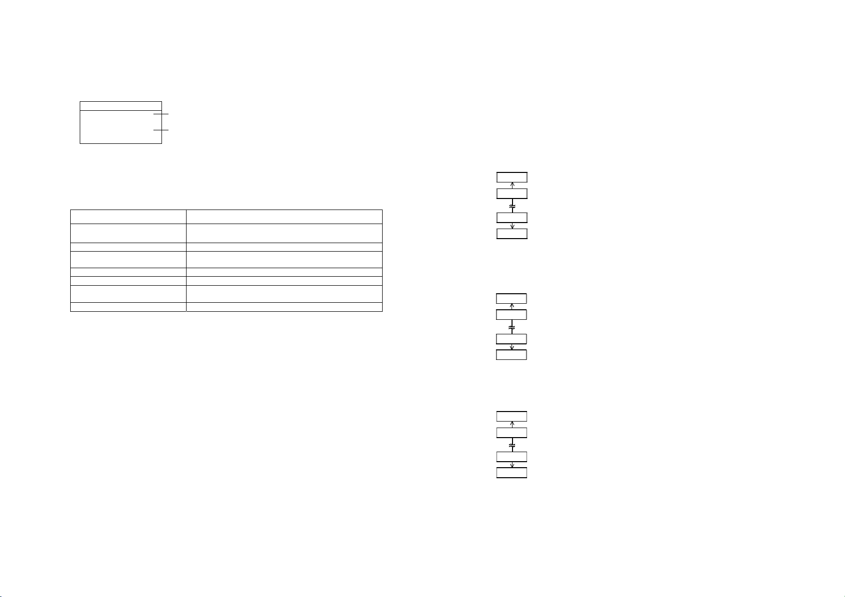
4.3 Retry
(1) ADJ RETRY POSITION
If writing data on a tag has failed, the printer feeds the RFID
tag forward or backward for the specified length in order to
retry the data write. When “0” is set for this parameter, this
function and a retry are not performed.
Only the value of –3mm or less or +3mm or more becomes
effective.
(Default value: 0 mm)
* "-": Forward, "+": Backward
(2) ISSUE RETRY LABELS
(3) READ RETRY
●The number of
times a tag read is
retried
Set the maximum number of retries to issue an RFID tag.
If printing does not succeed even after the maximum
number of retires, the printer stops, resulting in an error.
Moreover, when the issuing of an RFID tag has failed, the
printer prints the error pattern ("VOID) on the label.
(Default value: 3 times)
Set the maximum number of retries to read an RFID tag.
The printer retries to read the data in an RFID tag for up to
the specified number of times. If the timeout period expired
before the maximum number of retries have been done, the
printer stops the retries at this time.
Whenever the printer writes data onto an RFID tag, the
tag is read first. The maximum number of retries set
by this parameter becomes also effective in this pre-
read.
(Default value: 5 times)
99mm
98mm
-98mm
-99mm
255
254
1
0
255
254
1
0