manuals.online logo
Brands
  1. Home
  2. •
  3. Brands
  4. •
  5. Toshiba
  6. •
  7. Remote Control
  8. •
  9. Toshiba RBC-ASCU11-UL User manual

Toshiba RBC-ASCU11-UL User manual

ENDK NLLV FRNO GRHR DEPL RUCZ ITBG TRSK RO SESL PTET FIHU
-1-
[English] Installation manual and Owner’s manual Download /
[Español] Descarga del Manual de instalación y del Manual del propietario /
[Français] Téléchargement du manuel d'installation et du manuel du propriétaire
https://www.toshiba-carrier.co.jp/global/manual/rbc-ascu11-ul.htm
Packaging list
No. Appendix
Name Quantity No. Appendix
Name Quantity
1
Compact
remote
controller
1
4
Installation
Manual
1
5
Owner's
Manual
1
2
Screw
0.16"×0.98"
(M4×25mm)
2
6
Wire
terminal
2
3
Wood
screw
2
7
Plastic stud
2
Requirements of remote
controller installation site
Do not install the remote controller in a place
exposed to sunlight or outside air (near a
window or the like).
The temperature sensor is embedded both
in the remote controller and the indoor unit.
Switch between them for use.
(When delivery, the indoor unit temperature
sensor is used by default.)
When switching to the remote controller
temperature sensor, please follow the
instructions below to ensure that the sensor
can detect the average room temperature. If
not, it is recommended to use the sensor in the
indoor unit.
• Install the remote controller at a place
3.3 - 4.9ft (1-1.5 meters) above the ground.
• Do not install the remote controller behind
any obstacles where it cannot detect the
room temperature.
• Install the remote controller only in a room
that uses air conditioner.
• Install the remote controller vertically on the
wall or the like.
• Do not install the remote controller at a
place where it will be exposed to the direct
discharge air from the air conditioner.
• Do not install the remote controller on the
wall whose temperature greatly di󰀨ers from
room temperature.
How to wire the remote controller
■Wiring Diagrams
Since the remote controller cable has no
polarity, that’s ok if the indoor unit's terminal A
and terminal B are inversely connected
• Use non-polarity 2-core cable. W:White
B:Black
• Use AWG20 - AWG16
(0.5mm2-1.5mm2) cable.
Cable connection
Please use the attached wire connector to
connect the remote controller cable to the
indoor unit terminal board cable.
If crimping tools are not available, please use
other reliable methods for connection. Do
not only use the insulating tape to connect;
otherwise it can be dangerous.
Used by installation personnel —
Electrical operation and maintenance
Model:
RBC-ASCU11-UL
Compact wired remote controller
Installation Manual
-2-
How to install the remote controller
■Install the remote controller on the wall
Remote controller
body
Rear case
Wiring slot
Wall
Screws
0.16"×0.98"
(M4×25mm)
2.36in (60mm)
1. Insert a slot-type screwdriver or the like into
the groove on the lower side of the remote
controller body, and twist it to remove the
rear cover.
2. Cut the plastic stud in the accessory to a
suitable length for lling the gap between
the rear cover of the remote controller and
the studs of the bottom case, and then use
the M4 screws in the accessory to x the
rear cover to the bottom case through the
stud.
Note 1: Do not tighten the screws too
tightly, otherwise the rear cover will deform.
Note 2: When using studs to ll the gap,
make sure that the rear cover height is
uniform to prevent deformation.
3. Connect the remote controller cable (2-
core) to the cable of the remote controller
body. Conrm the terminal number of
indoor unit and connect the remote
controller cable correctly. (The remote
controller may be damaged if connecting
the power supply of indoor unit.)
4. Hang the remote controller body to the
hook on the rear cover and x it in place.
Note 3: Allow at least 1.2in (30 mm) of
space around the remote control.
DIP switch setup
The dial switch is located on the circuit board
of remote controller. When switching, remove
the rear cover. But be sure to turn o󰀨 the air
conditioner power rst.
(Factory default)
DIP switch
DIP
switch
1 2 3 4 5 6
Setting
item
Main
remote
controller
/ Sub
remote
controller
Backlight
Temperature
setting
Remote
controller
sensor
On/O󰀨
button
Operation
indicator
lamp
On
Sub
remote
controller
O󰀨 2°F On Long
press Dim
O󰀨
Main
remote
controller
On 1°F O󰀨 Short
press Bright
■
Main remote controller /Sub remote controller: 1
Use DIP switch 1 to set the main/sub remote
controller.
To use the remote controller as a sub remote
controller, slide the switch to the ON position.
To use the remote controller as a main remote
controller, slide the switch to the OFF position.
* For details, please refer to “Multiple Remote
Controller Installation Requirements.”
■Turn off LCD backlight: 2
Use DIP switch 2 to turn o󰀨 the LCD backlight.
Turn o󰀨 the backlight when the switch is turned
on, and turn on when the switch is turned o󰀨.
■Temperature setting as unit of 2°F: 3
You can use DIP switch 3 to change the display
unit of temperature setting.
The unit is set to 2°F when the switch is turned
on, and the unit is set to 1°F when the switch is
turned o󰀨.
■Remote controller sensor: 4
Use DIP switch 4 to set the remote controller
sensor. If to use the temperature sensor of the
remote controller, slide the switch to the ON
position.
If to use the temperature sensor of indoor unit,
slide the switch to the OFF position.
* For detailed information, please see
“Switching Temperature Sensor.”
■On/Off button setting: 5
Use DIP switch 5 to change the operation
mode of ON/OFF button to long press (approx.
4 seconds or more).
ENDK NLLV FRNO GRHR DEPL RUCZ ITBG TRSK ESRO SESL PTET FIHU
-3-
It is set to long press when the switch is turned
on, and it is set to normal (short press) when the
switch is turned o󰀨 .
■Operation indicator lamp: 6
Use DIP switch 6 to reduce brightness of
the operation indicator lamp of the remote
controller.
Set the lamp to be dim when the switch is turned
on and bright when the switch is turned o󰀨 .
Multiple remote controller
installation requirements
In a dual remote controller system, one or
more units are operated by multiple remote
controller.
■How to install
For a dual remote controller system, install the
remote controller as follows:
1. Set one of the remote controllers as the
main remote controller. (The default setting
is “Main Remote Controller.”)
2. Slide the DIP switch 1 on the remote
control ler circuit board to the ON position
to set the other remote controller as the
sub remote controller.
■Basic circuit diagram
• Use the remote controllers installed in two
di󰀨 erent locations to operate the same
indoor unit.
• Use the remote controllers installed in two
di󰀨 erent locations to centrally control multiple
indoor units.
* The main remote controller and sub
remote controller both can work in case of
connecting to any indoor unit.
• Standard wiring limitation (DIP switch 6: o󰀨 )
Wiring type
RVV: AWG20 - AWG16 (0.5mm² - 1.5 mm²) ×2
Total length of
remote control
wiring and inter-
wiring between
remote controllers
(L0+L1+L2+...Ln)
Only one
remote
controller is
furnished.
Two remote
controllers are
furnished (set
master and slave
controllers).
Two remote
controllers, including
one wire remote
controller.
No more than
1640ft (500m)
No more than
1310ft (400m)
Total length
of inter-wiring
between remote
controllers
(L1+L2+...Ln)
No more than 660ft (200m)
• Wiring limitation after brightness reduction
setting (DIP switch 6: on)
Wiring type
RVV: AWG20 - AWG16 (0.5mm² - 1.5mm²) ×2
Equivalent wiring
length between
remote controller
and indoor unit
(Leq)
No more than 490ft (150m)
Leq=∑x
0≤490ft (x≤n , x ∈N)
Total length of
remote control
wiring and inter-
wiring between
remote controllers
(L0+L1+L2+...Ln)
Only one remote
controller is
furnished and
brightness
reduction is set.
Two remote
controllers are
furnished (set
master and slave
controllers),
and one with
brightness
reduction setting.
Two remote
controllers,
including one
wire remote
controller,
and one with
brightness
reduction setting.
No more than 1150ft (350m)
Total length
of inter-wiring
between remote
controllers
(L1+L2+...Ln)
No more than 660ft (200m)
The remote controller is directly connected
to master indoor unit (most common mode)
(Leq=L0).
In this case,
1. The wiring between the remote controller
and master unit is no more than 490ft
(L0≤490ft),
2. The sum of wiring among indoor units is no
more than 660ft (L1+L2+…+Ln≤660ft).
-4-
Switching of temperature sensor
Both the remote controller and the indoor unit
have built-in temperature sensors, and the two
sensors cannot work at the same time.
The temperature sensor in the indoor unit is
the default sensor.
If to switch to the temperature sensor in the
remote controller, slide dial switch 4 on the
remote controller circuit board to the ON position.
Note 1: On the main remote controller, you can
switch to the sensor in the remote controller. (If
the remote controller is a sub remote controller,
it is unable to switch.)
Note 2: When using a separately sold remote
controller sensor, set the sensor inside the
remote controller to OFF.
Requirements
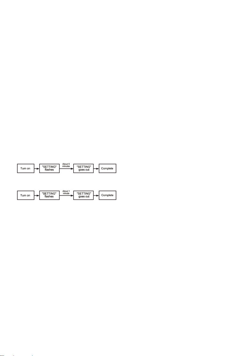
When using the remote controller for the rst
time, the initial operation after power on will
last for a while. This is not a fault.
<Initial turn on time>
Let the remote controller run for about 5 minutes.
<Turn on time after the second turn on>
Let the remote controller run for about 1 minute.
The address setting of the multi-split air
conditioners cannot be completed just by
turning on the power (“SETTING” always
ashes). You must perform the operation on
the outdoor interface circuit board to complete
the address setting. The remote controller
cannot be operated when setting the address.
It takes at most 10 minutes to set the address.
Remote controller test run setup
1. Press the ON/OFF button.
Turn o󰀨 the air conditioner.
2. Press the timer o󰀨 button and the “ △”
set button at the same time for at least 10
seconds. The LCD display area shows
“TEST” and becomes test mode.
3. The test run shall be performed in heating
or cooling mode.
• During test run, “TEST” is displayed on
the LCD display.
• When “TEST” is displayed, the
temperature cannot be adjusted.
• During test run, the machine will bear
a considerable load; therefore, it is
advisable not to carry out a test run
unless necessary.
Note 1: After power up, the outdoor unit will not
work within about 3 minutes; otherwise
the operation will stop.
4. After exiting the test run mode, press
the timer o󰀨 button again to ensure that
“TEST” on the LCD display disappears.(The
remote controller has a 60-minute timer o󰀨
function to prevent continuous test run.)
Remote controller DN setting
1. Press the On/O󰀨 button to shut down the
air conditioner.
2.
Hold down the menu button and the “ ▽”
setting button for at least 10s. The LCD
displays “SETTING” and the lower left
corner displays indoor unit address, e.g. 1-1.
After verifying the address, press the timer
o󰀨 button to access the DN setting mode.
3. After accessing the DN setting mode, use
the menu keys to switch between DN code
and data. Flashing means editable state.
Use “ △” and “ ▽” for setting. After this
is done, use the timer o󰀨 button to save
the setting (this step is required for each
setting). After the setting is over, press the
On/O󰀨 button to exit the DN setting mode.
Note 1: When in the DN setting mode, the fan
of the indoor unit will start working.
Before this, please make sure there
is no foreign matter around the fan
blades that may obstruct their normal
rotation and be cautious.
Remote controller state
monitoring mode
1. Hold down the menu button for 10s (in
either on or o󰀨 state) to access the remote
controller state monitoring mode.
2. After verifying the address, press the timer
o󰀨 button to access the state monitoring
mode. Use “ △” and “ ▽”to select the
code to check data.
• Refer to the Installation Manual supplied
with the indoor unit or outdoor unit or
service manual for details about the
check code and data.
3. Press the On/O󰀨 button to return to the
normal display interface.
EEV2401801

Other Toshiba Remote Control manuals

Toshiba Carrier RBC-AX22CUL User manual

Toshiba

Toshiba Carrier RBC-AX22CUL User manual

Toshiba RBC-AXU33UP-E User manual

Toshiba

Toshiba RBC-AXU33UP-E User manual

Toshiba RBC-AMS55E-ES User manual

Toshiba

Toshiba RBC-AMS55E-ES User manual

Toshiba RBC-AMSU51 -ES User manual

Toshiba

Toshiba RBC-AMSU51 -ES User manual

Toshiba RBC-AMT32E User manual

Toshiba

Toshiba RBC-AMT32E User manual

Toshiba RBC-AX22CE2 User manual

Toshiba

Toshiba RBC-AX22CE2 User manual

Toshiba RBC-ASCU11-E User manual

Toshiba

Toshiba RBC-ASCU11-E User manual

Toshiba RAV Heat User manual

Toshiba

Toshiba RAV Heat User manual

Toshiba RBP-RC001-E Operating instructions

Toshiba

Toshiba RBP-RC001-E Operating instructions

Toshiba RBC-AX22CE User manual

Toshiba

Toshiba RBC-AX22CE User manual

Toshiba 15V300PG User manual

Toshiba

Toshiba 15V300PG User manual

Toshiba MML-AP0074NH-E User manual

Toshiba

Toshiba MML-AP0074NH-E User manual

Toshiba RBC-IR2-PE User manual

Toshiba

Toshiba RBC-IR2-PE User manual

Toshiba RBC-AS41E User manual

Toshiba

Toshiba RBC-AS41E User manual

Toshiba Carrier RBC-AX22CUL User manual

Toshiba

Toshiba Carrier RBC-AX22CUL User manual

Toshiba RBC-SRC-PE User manual

Toshiba

Toshiba RBC-SRC-PE User manual

Toshiba RBC-AMSU51-ES User manual

Toshiba

Toshiba RBC-AMSU51-ES User manual

Toshiba 46WM48 Series Use and maintenance manual

Toshiba

Toshiba 46WM48 Series Use and maintenance manual

Toshiba RBC-SR1-PE User manual

Toshiba

Toshiba RBC-SR1-PE User manual

Toshiba RBC-AMT32E User manual

Toshiba

Toshiba RBC-AMT32E User manual

Toshiba V211UK User manual

Toshiba

Toshiba V211UK User manual

Toshiba Carrier TCB-AX21UL User manual

Toshiba

Toshiba Carrier TCB-AX21UL User manual

Toshiba TCB-AX21E User manual

Toshiba

Toshiba TCB-AX21E User manual

Toshiba RBC-AS21E User manual

Toshiba

Toshiba RBC-AS21E User manual

Popular Remote Control manuals by other brands

EWM RTP 1 operating instructions

EWM

EWM RTP 1 operating instructions

D.A.C.E SOLO Installation & owner's manual

D.A.C.E

D.A.C.E SOLO Installation & owner's manual

Panasonic CZ-01ESM11P Operation manual

Panasonic

Panasonic CZ-01ESM11P Operation manual

point pro Series user manual

point

point pro Series user manual

Ksenia opera KSI7700000.001 user guide

Ksenia

Ksenia opera KSI7700000.001 user guide

RadioLink RC4GS V3 instruction manual

RadioLink

RadioLink RC4GS V3 instruction manual

Dish Network Platinum PVR Remote Control user guide

Dish Network

Dish Network Platinum PVR Remote Control user guide

Spektrum DX8 instruction manual

Spektrum

Spektrum DX8 instruction manual

Lynxspring KANEsys JENE-PCLCD-R installation guide

Lynxspring

Lynxspring KANEsys JENE-PCLCD-R installation guide

INVENTOR OMI-09 owner's manual

INVENTOR

INVENTOR OMI-09 owner's manual

Hahnel Inspire instruction manual

Hahnel

Hahnel Inspire instruction manual

Firstech CompuSTAR 2WFMR user guide

Firstech

Firstech CompuSTAR 2WFMR user guide

One Forall SmartControl URC-7960 manual

One Forall

One Forall SmartControl URC-7960 manual

ComfortBreeze R71A/(C)E owner's manual

ComfortBreeze

ComfortBreeze R71A/(C)E owner's manual

pro master Wireless Remote Shutter operating instructions

pro master

pro master Wireless Remote Shutter operating instructions

mundoclima RG57 Selection Manual

mundoclima

mundoclima RG57 Selection Manual

C.P. Electronics UHS5 installation guide

C.P. Electronics

C.P. Electronics UHS5 installation guide

Data Video Teleprompter WR-100 instruction manual

Data Video

Data Video Teleprompter WR-100 instruction manual

manuals.online logo
manuals.online logoBrands
  • About & Mission
  • Contact us
  • Privacy Policy
  • Terms and Conditions

Copyright 2025 Manuals.Online. All Rights Reserved.