8
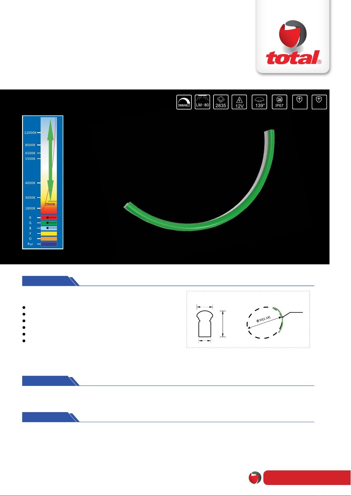
LED SILICONE NEON FLEX
NSR2-6MD-H
08
Repair should be operated by a qualied technician, if the external circuit or main line of this product is damaged.
The parameters given in this manual are typical values and for reference only.
All illustrations and drawings in this manual are for reference.
This product is subject to change without notice.
LED lighting products belongs to electronic products, please do recycling treatment according to the relevant WEEE directives.
Statements:
Recycling:
Warning
Do not disassemble or retrot the light. Do not touch the surface of the
light with a sharp object.
Do not do live-line working during installation,especially for high voltage
product.
Do not use any organic chemical solvents.
Use neutral glass adhesive to x this product and it needs to be dried 4
hours in the open environment after operation.
Treat the ends and the circuit connection points that are not connected
to the main line with insulation,waterproof, and anti-corrosion in the
installation.
Use 18AWG (0.75mm2 cross-sectional area) or thicker core wire to
avoid adverse consequences caused by overheating, if the power cable
need to lengthen.
Make sure the input voltage meets the requirements and lines are
connected correctly before lighting on.
This product is for signage, and do not use as general lighting.
Series connection within the max run.
The length of the power cable between the power supply and the led
strip should not exceed 2 meters.Otherwise, large circuit loss will lead
to inconsistent brightness.
Installation, maintenance and repair should be operated by a qualied
technician.
Quick Guide
Problems
All LEDs can
not light on.
LEDs can not
light on partly.
Brightness of
LED
is inconsistent
tor insufcient.
LED icker.
Automatic power protection
from the open or short
circuit in output of the power
supply. Fix the short circuit problem.
Correctly connection
Check the power supply
system to x it.
Replace with more powerful
power
Make sure the working voltage of
the product within ±5% of standard
voltage, or keep balance by circuit
power consumption.
Reduce the quantities of the product in
series connection to meet requirement.
Fix the short circuit problem.
Wrong connection of power
supply.
Some switching mode power
supplies are not powered.
Power supply line error.
Mistaken wire connection of
some of products
Power overloaded.
Connection point fault. Remove bad connection point.
Replace a new power supply.
Please follow the instructions
Power supply circuit
excessive consumption.
Excessive quantities in series
connection of the product
Switching power supply
failure.
Wrong Installation or use of
products
Reasons
No electric supply.
Solutions
Common Faults and Troubleshoot
Common Faults and Troubleshoot