Toyota PK6A3-33HT1 User manual

TOYOTA 4RUNNER 2020 – DASH CAMERA
PREPARATION
Page 1 of 24
Issue D: 11/06/19
Part #: PK6A3-33HT1 and PK6A4-33HW1
Conicts:
KitContents
AdditionalItems
(may be required)
Item# Description
RecommendedSequence
ofApplication
Item# Description
RecommendedTools
Personal&VehicleProtection Description
Vehicle Protection Blankets, Part Boxes
SpecialTools
Dash Camera Mounting Template IADS# 4RU20-0011
InstallationTools
Screwdriver #2 Phillips, Flat Blade Jeweler’s
Panel Removal Tool Toyota SST# 00002-06001-01
Side Cutters
Torque Wrench
Battery: 48 in•lbf (5.4 N•m),
Ground Bolt: 75 in•lbf (8.5 N•m)
Knee Airbag: 88.5 in•lbf (10 N•m)
Pliers Needle-nose, Universal
Scissors
Tape Measure / Ruler
Ratchet
Tape Electrical, Masking
Socket 10mm, Extension
SpecialChemicals
Cleaner VDC Approved Cleaner
Glass Cleaner Toyota Touch Glass Cleaner
Service Part #’s
PK6A4-33HT1
Dash Camera
Wire Harness
Wire Channel Vinyl sheet
Wire Tie Foam Tape
PK6A4-33HS0
PK6A4-33HC0
x1 x1
x1 x18
x1
x2 x2 x1
x1
PK6A4-33HM1
x1
MicroSD Card
with Adapter Owner’s Manual
Harness Clip
Dash Camera
Side Cover
WireHarnessKit:PK6A4-33HW1
DashCameraKit:PK6A3-33HT1
Not used - Discard
X

TOYOTA 4RUNNER 2020 – DASH CAMERA
PREPARATION
Page 2 of 24
Issue D: 11/06/19
Legend
Do not proceed until process
has been completed.
Follow steps carefully to
avoid damaging the
Vehicle or Accessory.
Use caution to avoid injury.
Used in Figures to call attention
to specic tools recommended
for the process.
Highlights a change in
installation with respect
to previous issue.
Indicates that torque is related
to safety.
Wire Tie location and number.
xx
AccessoryInstallationPractice(readbeforeinstallation)
Care must be taken when installing this accessory to ensure damage does not
occur to the vehicle. The installation of this accessory should follow approved
guidelines to ensure a quality installation.
These guidelines can be found in the “Toyota and Scion Accessory Installation
Practices” or “Lexus Accessory Installation Practices” document.
This document covers such items as:
•Installation Instructions
• Safety
•Vehicle Protection
•Vehicle Disassembly/Reassembly
•Electrical Component Disassembly/Reassembly
• Use of Special Chemicals
•Temperature
•Torque Recheck
• Window Label Installation
•TPMS Check
Please refer to ETAS for a copy of this document.
TableofContents
I. Preparation ............................................................................................................................ 1–3
1. Table of Contents ................................................................................................................................................2
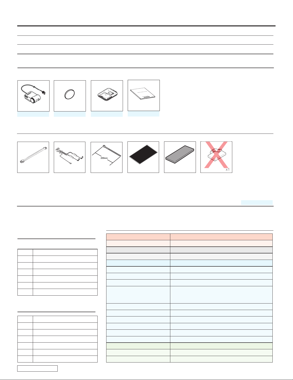
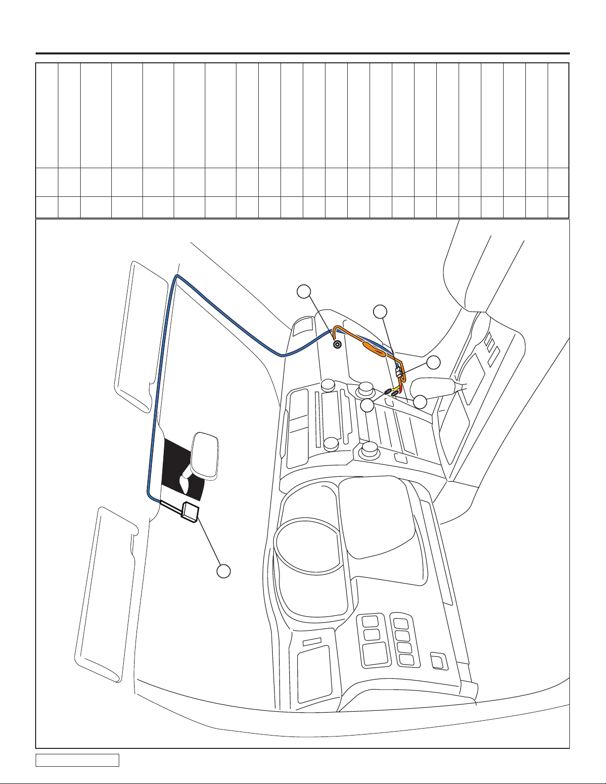
2. Wire Harness Outline ..........................................................................................................................................3
II. Procedure ............................................................................................................................ 4–21
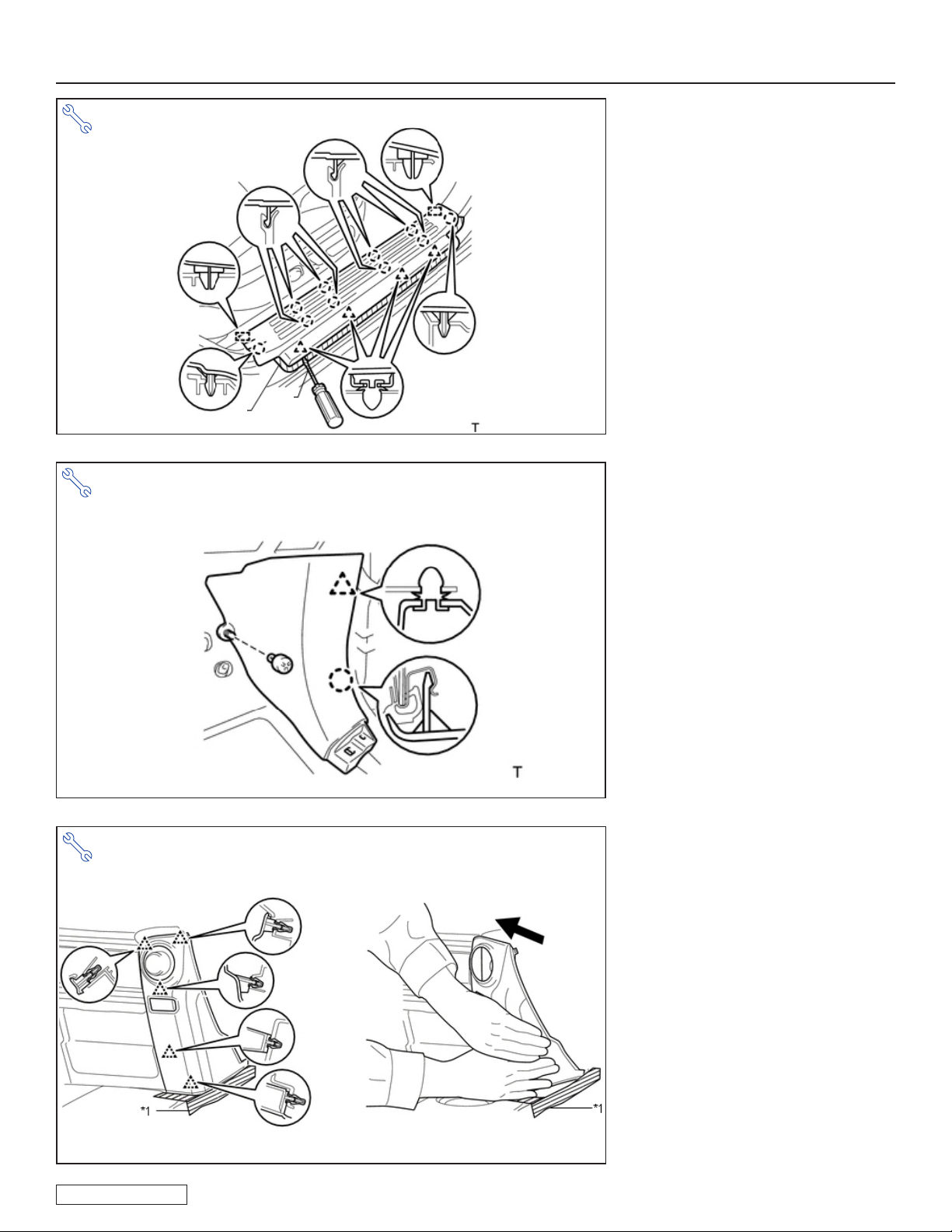
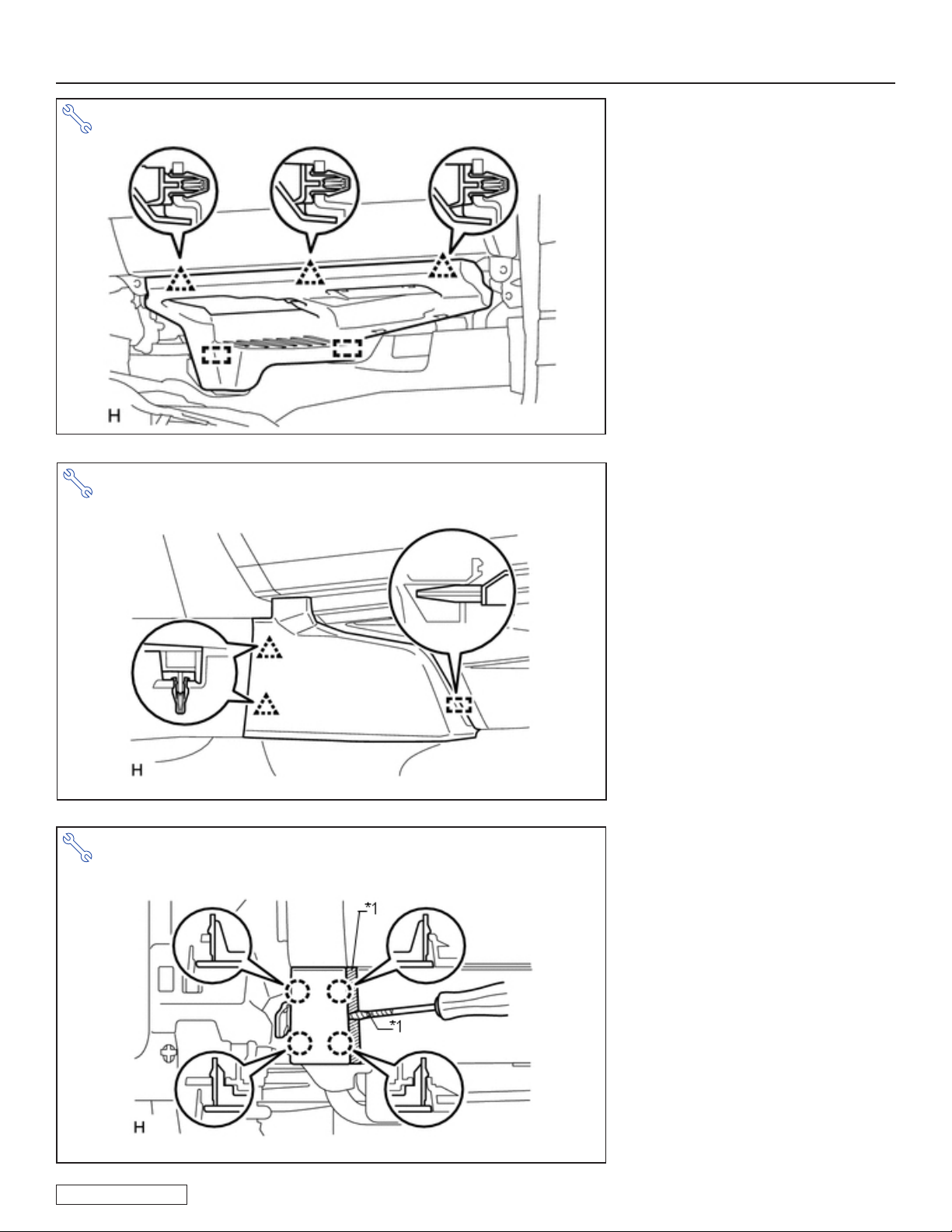
1. Vehicle Disassembly ....................................................................................................................4
2. Dash Camera Installation ............................................................................................................ 10
3. Wire Harness Installation ............................................................................................................ 13
4. Vehicle Reassembly. .................................................................................................................. 19
III. Checklist ............................................................................................................................ 22–24
1. Accessory Function Checks ..............................................................................................................................22
2. Vehicle Appearance Check ...............................................................................................................................22
3. Vehicle Function Checks ...................................................................................................................................23
PrecautionsforInstallation
Contents indicated by and in this manual must be carefully followed during the installation. If they are ignored,
functions of the accessory maybe hindered, as well as personal injury or damage to the vehicle may result. Always carry
out the installation as instructed.
When the vehicle parts are removed, keep all tapping screws, bolts and nuts organized so that the reassembly will
proceed correctly.
Do NOT remove vehicle parts except for those that are specied in the manual.
NOTE: Pictures depicted in this Installation Manual may not reect the current model and model year vehicle.

TOYOTA 4RUNNER 2020 – DASH CAMERA
PREPARATION
Page 3 of 24
Issue D: 11/06/19
Toyota4Runner
WireHarnessOutline
DC Vehicle Description
A
-
Dash Camera
B
-
5P Blue (Dash
Camera connector)
C
-
5P Blue
(for Dash Camera)
D G1 Ground Terminal
E F42 Red Wire Splicing
Connector
F F42 Yellow Wire Splicing
Connector
E
D
B
C
A
F

TOYOTA 4RUNNER 2020 – DASH CAMERA
PROCEDURE
Page 4 of 24
Issue D: 11/06/19
1Front No.1 Assist Grip Plugs
2No. 1 Assist Grip
3 Front Pillar Garnish RH
4No. 1 Forward Recognition
Cover
5Drive Motor Switch
(if equipped)
6Map Light Assembly
7Door Scuff Plate Assembly
8 Cowl Side Trim Board RH
9No. 2 Instrument Panel
Cluster Finish Panel Garnish
10 No. 2 Instrument Panel
Under Cover Sub-Assembly
11 Front No. 2 Console Box
Insert
12 Lower Instrument Cover LH
13 Lower No. 2 Instrument
Panel Airbag Assembly
14 Instrument Panel Box Door
Cover (3 pcs.)
15 Lower Instrument Panel
Sub-Assembly
Disconnect all Corresponding
Connectors.
DisassemblyOverview
11
7
9
8
3
10
1
12
1. VehicleDisassembly
a. Place the Vehicle in Park with
the Parking Brake set.
b. Disconnect the Negative
Battery Terminal.
• Protect the Fender.
• Note the Battery Cable Position
as it will be re-installed in the
same position.
CAUTION:Do not touch the
Positive Terminal.
10mm Socket Fig. 1-1
13
14
15
2
6
5
4

TOYOTA 4RUNNER 2020 – DASH CAMERA
PROCEDURE
Page 5 of 24
Issue D: 11/06/19
c. Remove Front No. 1 Assist
Grip Plug RH.
•Using a protective tape wrapped
screwdriver (*1), detach the 2
claws and remove the front No. 1
assist grip plug RH.
d. Remove No. 1 Assist Grip.
• Remove the 2 bolts.
•Detach the 2 claws and remove
the No. 1 assist grip.
e. Remove the Front Pillar
Garnish RH.
•Detach the clip and 3 guides and
remove the front pillar garnish RH.
Panel Removal Tool Fig. 1-4
10mm Socket Fig. 1-3
Panel Removal Tool, Flat Blade Screwdriver Fig. 1-2
*1

TOYOTA 4RUNNER 2020 – DASH CAMERA
PROCEDURE
Page 6 of 24
Issue D: 11/06/19
f. Remove No.1 Forward
Recognition cover.
•Detach the 2 clips and 2 guides to
remove the cover as shown in the
illustration.
Clip
Guide
g. Remove Drive Monitor Switch
(w/ Drive Monitor Switch).
•Detach the 4 claws to remove the
drive monitor switch.
• Disconnect the connector.
h. Remove Map Light Assembly.
•Open the cover (w/o Drive Monitor
Switch).
• Remove 2 screws.
•Detach the 2 clips to remove the
map light assembly.
• Disconnect the connector.
Panel Removal Tool Fig. 1-6
10mm Socket, Panel Removal Tool Fig. 1-7
Fig. 1-5
Downward

TOYOTA 4RUNNER 2020 – DASH CAMERA
PROCEDURE
Page 7 of 24
Issue D: 11/06/19
k. Remove No. 2 Instrument
Panel Cluster Finish Panel
Garnish.
• Open the instrument cluster nish
panel lid.
•Put protective tape (*1) around
the No. 2 instrument cluster nish
panel garnish.
• Grip the No. 2 instrument cluster
nish panel garnish and pull it
diagonally upward toward the rear
to detach the 5 clips and remove
the No. 2 instrument cluster nish
panel garnish.
j. Remove Cowl Side Trim
Board RH.
• Remove the clip.
•Detach the clip and claw and remove
the cowl side trim board RH.
i. Remove Door Scuff Plate
Assembly RH.
•Put protective tape (*1) around the
door scuff plate assembly RH.
•Using a protective tape wrapped
screwdriver, detach the 4 clips, 10
claws and 2 guides to remove the
door scuff plate assembly RH.
Flat Blade Screwdriver, Panel Removal Tool Fig. 1-8
Panel Removal Tool Fig. 1-9
*1
*1
Panel Removal Tool Fig. 1-10

TOYOTA 4RUNNER 2020 – DASH CAMERA
PROCEDURE
Page 8 of 24
Issue D: 11/06/19
n. Remove Lower Instrument
Cover LH.
•Put protective tape (*1) around
the lower instrument cover LH.
•Using a protective tape (*1)
wrapped screwdriver, detach
the 4 claws and remove the
lower instrument cover LH.
m. Remove Front No. 2 Console
Box Insert.
•Detach the 2 clips and guide to
remove the front No. 2 console
box insert.
l. Remove No. 2 Instrument
Panel Under Cover Sub-
Assembly.
•Detach the 3 clips and 2 guides
and disconnect the connector to
remove the No. 2 instrument panel
under cover sub-assembly.
Panel Removal Tool Fig. 1-12
Panel Removal Tool Fig. 1-11
Flat Blade Screwdriver/Panel Removal Tool Fig. 1-13

TOYOTA 4RUNNER 2020 – DASH CAMERA
PROCEDURE
Page 9 of 24
Issue D: 11/06/19
o. Remove Lower No. 2
Instrument Panel Airbag
Assembly.
• Remove the 3 bolts.
•Detach the 8 claws and remove
the instrument panel airbag.
CAUTION: Do not disconnect the
Vehicle’s Connector.
p. Wrap the Airbag in a Blanket
or the like and place it on top
of a box.
CAUTION: Prevent stress on the
Airbag Harness.
q. Remove Instrument Panel
Box Door Cover.
HINT: Use the same procedure for all 3
instrument panel box door covers.
•Using a protective tape wrapped
screwdriver (*1), detach the 2
claws and 2 guides and remove the
instrument panel box door cover.
10mm Socket, Extension, Panel Removal Tool Fig. 1-14
Fig. 1-15
Flat Blade Screwdriver/Panel Removal Tool Fig. 1-16

TOYOTA 4RUNNER 2020 – DASH CAMERA
PROCEDURE
Page 10 of 24
Issue D: 11/06/19
2. DashCameraInstallation
a. Cut the Foam Tape into
3 pieces of (30x80mm) and
2 pieces of (63x80mm) sized.
Tape Measure/Ruler, Scissors Fig. 2-1
r. Remove Lower Instrument
Panel Sub-Assembly.
• Remove the 3 screws and 2 bolts.
• Detach the 10 clips and guide.
• Remove wires for glove box lamp,
and remove the lower instrument
panel.
Phillips Screwdriver, 10mm Socket, Panel Removal Tool Fig. 1-17
Tape Measure/Ruler, Scissors Fig. 2-2
Vinyl Sheet
2 x (25x200 mm)
25mm
25mm
b. Cut out 2 (25x200mm) sized
pieces from the Vinyl sheet
as shown.
250mm
80mm
30mm
30mm
30mm
63mm
63mm

TOYOTA 4RUNNER 2020 – DASH CAMERA
PROCEDURE
Page 11 of 24
Issue D: 11/06/19
Tape Measure/Ruler, Masking Tape Fig. 2-5
Fig. 2-4 g. Slide the protection vinyl tube
until it covers the whole dash
camera wire up to the Wire
Channel as illustrated.
NOTE:Harness has overlapped
vinyl tube. Slide the tube nearest
to the camera until position
shown in g. 2-4. Do not cut the
vinyl tube.
h. Use Glass Cleaner to clean
the inside Windshield of the
indicated mounting location.
DIOOnly(stepsi-j)
i. Measure 75mm to the left of
the Rearview Mirror channel
and mark it with Masking
tape.
j. Measure 70mm from the
edge of the shade-band and
mark it with Masking tape.
NOTE:Donottouchthe
cameralensduringinstall.
c. Measure the Wire Channel to
90mm length and cut to size
as shown.
d. Insert the Dash Camera Wire
into the Wire Channel, then
insert the Wire Channel into
the Dash Camera as shown.
e. Tighten the screw making
sure the Camera angle
indicator is pointing at the
3rd Mark as shown.
f. Install the Dash Camera’s
side cover by aligning with
slots in camera housing, then
turn clockwise to lock.
Tape Measure/Ruler, Scissors, Phillips Screwdriver Fig. 2-3
3rd Mark
Camera Angle
70mm
75mm
(Shade-band)
Larger end
Cut
90mm

TOYOTA 4RUNNER 2020 – DASH CAMERA
PROCEDURE
Page 12 of 24
Issue D: 11/06/19
o. Route the Dash Camera wire
between the Headliner and
the Roof.
NOTE: Be careful not to damage
the Headliner.
NOTE:After routing the Dash
Camera wire, conrm the Wire
Channel is straight. If not, adjust
the Wire Channel to achieve
condition in Fig. 2-6. Conrm the
Dash Camera wire is properly
seated (≥10mm behind the
Headliner edge).
PPOOnly
m. Line up the Dash Cam
Mounting Template (IADS#
4RU20-0011) on the
windshield to the LH side of
the rearview mirror as shown.
•Use masking tape to attach
template to the windshield.
n. Attach the Dash Camera
on the Windshield aligning
it within the Dash Cam
Mounting Template.
HINT: Align camera to location
shown by the template. Conrm
camera is parallel with mirror
before xing position.
Panel Removal Tool Fig. 2-8
Masking Tape Fig. 2-7
NOTE:Be careful not to damage
the Headliner.
NOTE:To achieve maximum
bond strength of adhesive, the
attachment surface temperature
must be at 60°F or higher.
k. Attach the Dash Camera on
the Windshield as shown.
• Peel the protective backing off
the Dash Camera
• Press rmly with palm on the Dash
Camera for 10 seconds.
l. Start routing Dash Camera
Wire between the Headliner
and the Roof and insert the
Wire Channel end into the
Headliner.
Panel Removal Tool Fig. 2-6

TOYOTA 4RUNNER 2020 – DASH CAMERA
PROCEDURE
Page 13 of 24
Issue D: 11/06/19
q. Route the Dash Camera wire
through the IP opening and
secure using 2 Wire Ties (#3,
#4) as shown.
NOTE:Do not secure to the
vehicle drain tube if equipped.
3. WireHarnessInstallation.
a. Wrap the Wire Harness Ground
Wire starting from the Ground
Terminal using 2 (25x200mm)
pieces of Vinyl sheet with a
10mm overlap in between,
and secure with electrical tape
closed (spiral wrap).
Side Cutters Fig. 2-10
Tape Measure/Ruler, Scissors Fig. 3-1
Ground Wire 390mm
10mm
Overlap
Ground Terminal
Side Cutters Fig. 2-9
1
2
p. Route the Dash Camera wire
along and behind the vehicle
harness, then secure using
2 vehicle harness clips and 2
Wire Ties (#1, #2).
•Rotate the Wire Tie Ratchet away
from the A-pillar cover.
NOTE:Do not secure Dash
Camera wire to the Curtain Side
Air Bag or pass wire across the
Curtain Side Airbag.
NOTE:Do not secure to the
vehicle drain tube if equipped.
4
3
2
4

TOYOTA 4RUNNER 2020 – DASH CAMERA
PROCEDURE
Page 14 of 24
Issue D: 11/06/19
b. Route the Wire Harness
Ground Wire behind the
reinforcement, locate “G1”
Ground attachment upper
right side of the Glove box
area and remove the Bolt.
c. Place the Wire Harness
Ground Terminal underneath
the vehicle ground terminal
and reinstall the Bolt.
Torque: 75 in•lbf (8.5 N•m).
NOTE:Place the Wire Harness
Ground Terminal behind the vehi-
cle ground terminal at 90 degrees.
e. Disconnect Connector F42
(40P, White) located on the
left side of the blower motor.
f. Remove the electrical tape
closest to the connector
securing the wires.
10mm Socket, Torque Wrench Fig. 3-2
d. Secure both the Dash
Camera wire and Ground
wire to the vehicle harness
with 1 Wire Tie (#5).
Side Cutters Fig. 3-3
Fig. 3-4
5

TOYOTA 4RUNNER 2020 – DASH CAMERA
PROCEDURE
Page 15 of 24
Issue D: 11/06/19
WireSplicingConnector
Example(stepsg-i)
g. Place the Vehicle Wire in the
Splicing Connector housing.
h. Fold the Splicing Connector
Housing along the pleat line.
i. Pinch the Splicing Connector’s
housing together until a click
sound can be heard twice.
VERIFY: Ensure locks have
engaged on both sides.
NOTE: Ensure there is no gap
between the upper and lower half
of the Splicing Connector locks.
Fig. 3-5
Vehicle Wire
Dash Camera
Harness Wire
Splicer Connector
Housing
Lock Engaged
No Gap
Fig. 3-6
*Click*
*Click*
No Gap
EXAMPLE

TOYOTA 4RUNNER 2020 – DASH CAMERA
PROCEDURE
Page 16 of 24
Issue D: 11/06/19
j. Route the Wire Harness with
T-taps to the Connector F42.
NOTE:Reference steps g-i for
Wire Splicing Connector example.
k. Install the Wire Harness
with the Red Wire Splicing
Connector to the BLUE wire
on Pin# 1 of Connector F42
(40P, White).
Pliers Fig. 3-7
Pliers Fig. 3-8
Pliers Fig. 3-9
20 19 18 17 16 15 14 13 12 11 10 9 8 7 4 2 1
3
2425262728293031323334353637383940 2223 21
56
20 19 18 17 16 15 14 13 12 11 10 9 8 7 4 2 1
3
2425262728293031323334353637383940 2223 21
56
Connector View from Wire Side
Splicing Connector
Splicing Connector
Hinges
Hinges
Pliers
Pliers
Blue Wire
Violet Wire
Splicing Connector
Foam Tape (30x80mm) Foam Tape (63x80mm)
Fuse
NOTE:Reference steps g-i for
Wire Splicing Connector example.
l. Install the Wire Harness
with the Yellow Wire Splicing
Connector to the VIOLET wire
on Pin# 21 of Connector FN1
(40P, White).
NOTE:Stagger the T-tap connec-
tions (do not place T-taps side by
side).
m. Wrap the 2 Wire Harness
Fuse using 2 (63x80mm)
pieces of Foam tape.
n. Wrap the Splicing connectors
using 2 (30x80mm) pieces of
Foam tape.

TOYOTA 4RUNNER 2020 – DASH CAMERA
PROCEDURE
Page 17 of 24
Issue D: 11/06/19
Fig. 3-10
q. Secure one of the Wire Har-
ness Fuse to the vehicle wire
harness with 1 Wire Tie (#6).
o. Reconnect Connector F42 to
the ECU.
p. Route the Wire Harness
with Fuses along the vehicle
harness going towards
underneath the blower motor.
Side Cutters Fig. 3-11
r. Connect the Dash Camera Blue
Connector to the Wire Harness
Blue Connector.
s. Wrap the Wire Harness Male
Blue Connector with 1 piece of
(30x80mm) sized Foam tape.
NOTE:Prior to securing Wire Ties
(#7, #8) apply electrical tape to the
vehicle harness and dash camera
wire.
t. Secure Wire Harness with the
Ground wire to the vehicle
harness with 1 Wire Tie (#7).
u. Loop the Ground Wire excess
wire and route with the Dash
Camera Harness along the
vehicle harness and secure
with 1 Wire Tie (#8).
v. Secure the Wire Harness
to the vehicle harness with
1 Wire Tie (#9).
NOTE:Rotate the Wire Ties (#7,
#8, #9) Ratchet toward the bulkhead
and away from the undercover.
6
Side Cutters Fig. 3-12
8
7
9

TOYOTA 4RUNNER 2020 – DASH CAMERA
PROCEDURE
Page 18 of 24
Issue D: 11/06/19
x. Bundle up as necessary the
excess Ground Wire using
electrical tape and secure with
Dash Camera Wire Harness
to the vehicle harness using 1
Wire Tie (#11) as shown.
w. Secure the Wire Harness Fuse
and the excess Wire Harness
to the vehicle harness using 1
Wire Tie (#10) as shown.
Side Cutters Fig. 3-13
Side Cutters Fig. 3-14
7
5
9
8
10
11

TOYOTA 4RUNNER 2020 – DASH CAMERA
PROCEDURE
Page 19 of 24
Issue D: 11/06/19
b. Install the Lower Instrument
Panel Sub-Assembly.
• Install wires for glove box
lamp,and install the lower
instrument panel by attaching the
10 clips and guide.
• Install the 3 screws and 2 bolts.
c. Install the Instrument Panel
Box Door Covers (3).
Fig. 4-1
5
9
7
8
13
6
15
43
2
1
14
ReassemblyOverview
4. VehicleReassembly.
a. Reassemble the Vehicle.
10mm Socket, Phillips Screwdriver Fig. 4-2
2
1
1Lower Instrument Panel Sub-
Assembly
2Instrument Panel Box Door
Cover (3 pcs.)
3Lower No. 2 Instrument Panel
Airbag Assembly
4Lower Instrument Cover LH
5 Front No. 2 Console Box Insert
6No. 2 Instrument Panel
Under Cover Sub-Assembly
7No. 2 Instrument Panel
Cluster Finish Panel Garnish
8 Cowl Side Trim Board RH
9Door Scuff Plate Assembly
10 Map Light Assembly
11 Drive Motor Switch
(if equipped)
12 No. 1 Forward Recognition Cover
13 Front Pillar Garnish RH
14 No. 1 Assist Grip
15 Front No.1 Assist Grip Plugs
VERIFY: That panels t together
properly, with no uneven gaps.
VERIFY: That all Connectors are
plugged in.
10
11
12

TOYOTA 4RUNNER 2020 – DASH CAMERA
PROCEDURE
Page 20 of 24
Issue D: 11/06/19
d. Install the Lower No. 2
Instrument Panel Airbag
Assembly.
•Attach the 8 claws to install the
instrument panel airbag.
• Install the 3 bolts.
NOTE: Install the temp-set hook
on knee airbag before securing
airbag clips (triangle) and bolts.
If this process is not followed,
the airbag bracket may become
deformed.
Torque: 88.5in•lbf(10N•m).
e. Install the Lower Instrument
Cover LH.
f. Install the Front No. 2 Console
Box Insert.
g. Install the No. 2 Instrument
Panel Under Cover Sub-
Assembly.
h. Install the No. 2 Instrument
Panel Cluster Finish Panel
Garnish.
i. Install the Cowl Side Trim
Board RH.
j. Install the Door Scuff Plate
Assembly RH.
k. Install Map Light Assembly.
l. Install Drive Motor Switch
(if equipped).
m. Install No. 1 Forward
Recognition Cover.
n. Install the Front Pillar Garnish
RH.
•Attach the clip and 3 guides to
install the front pillar garnish RH.
o. Install the No. 1 Assist Grip.
•Attach the 2 claws to install the
No. 1 assist grip.
• Install the 2 bolts.
Torque: 9lb-ft(12N•m).
p. Install the Front No. 1 Assist
Grip Plugs (2).
10mm Socket, Extension, Torque Wrench Fig. 4-3
10mm Socket Fig. 4-4
54
6
7
8
9
10mm Socket Fig. 4-5
10
11
12
This manual suits for next models
1
Table of contents
Other Toyota Dashcam manuals

Toyota
Toyota PZQ85-33270 Install guide

Toyota
Toyota 2.0 Series User manual

Toyota
Toyota VENZA PT949-08210 User manual

Toyota
Toyota PT949-34222 User manual

Toyota
Toyota CAMRY PT949-08210 User manual

Toyota
Toyota PT949-34220 User manual

Toyota
Toyota N656 User manual

Toyota
Toyota PZQ90-89011 User manual

Toyota
Toyota PZQ85-33270 Install guide