Olsberg 14/691-3 User manual

OLSBERG
•
Instruction Manual
Static Storage Heater manual 14/69_-3 and automatic 14/69_-4
Static Storage Heater intelligent 14/70_-3

19
This instruction leaflet must be:
• handed to the heater user after installation. The user is also to be instructed on the way this electric storage
heater works.
• read carefully, retained for further use, and handed over to a new owner/user.
• given to any maintenance engineer before repair work is carried out.
Please read this instruction carefully. It contains important information on safety, installation, use and mainte-
nance of the heater.
The manufacturer cannot be held responsible for problems occurring when the following instructions are not
adhered to. The appliances must only be used for the function intended.
Note: Packaging materials, replacement parts and heaters or heater parts to be scrapped must all be dis-
posed of correctly according to regulations.
Disposal of old heaters
Old electric and electronic devices often contain valuable materials. But they may also contain
harmful ingredients which were necessary for their function and security. In normal waste disposal
or incorrect treatment they could be harmful to the environment. Please help to protect our
environment! Please do not add your old heater to normal waste in any case. Dispose of your old
heater according to the local regulations.
General guarantee conditiones
Dear customer,
in guarantee case the country specified rights are valid which you may claim directly towards your dealer.

20
Installation Instructions
•Delivery and packaging
To facilitate transport and handling, the heater
cabinet (with built-in heating elements) and the
bricks (SP36, SP38) are packaged separately.
The packaging has be limited to the minimum nec-
essary for safe transport and is made entirely of
recyclable materials.
fig.1
•Electrical connection
The storage heater is connected to a single-phase
circuit.
Voltage: 1/N/PE ~ 230V
Charge period: 8h
According to safety instructions, each electrical cir-
cuit must be protected by a circuit breaker with an
all-pole contact opening of 3mm minimum.
•Heater positioning, minimum clearances
The heater is to be positioned with the feet pre-
mounted against a load-bearing wall and secured
according to this instruction and using the fixing
materials provided.
It is preferable to place the heater under a window
so that the cold air in this vicinity can be warmed,
causing natural convection.
The floor and/or the wall must be able to take the
weight of the heater. Please, therefore, note care-
fully the weights given in the Technical Data sec-
tion of this instruction. If in doubt, consult a building
engineer or architect.
The minimum clearances in fig.2 are to be ad-
hered to when positioning this heater.
To facilitate installation we recommend keep-
ing a distance of 150mm min. to the sides of
the heater.
fig.2
•Rating label, manufacturing (batch) number
The rating label (fig.3) contains all the data specific
to the heater model. The rating label is found on
the bottom right of the heater rear panel.
The manufacturing, or batch number is on a sepa-
rate label on the right hand side of the heater plinth
(remove front panel).
The model and batch numbers are important for
repair and spare parts purposes.
model
weight
fig.3
14/691-3 14/695-3
14/692-3
14/692-4
14/702-3
14/696-4
14/693-3
14/693-4
14/703-3
14/694-3
14/694-4
14/704-3
A 125 235 345 395 505 725
B 110 110 110 140 140 140
L 345 455 565 675 785 1005

21
•Technical Data
Model
Nominal
charge
kW
Storage
capacity
kWh
Voltage
Dimensions
Width x Depth x Height 1)
mm
Weight
ca. kg
Heating
elements Core brick
packs
manual
14/691-3 0,85 6,8 345x170x700 48 1x0,85kW 2x SP36
14/695-3 1,3 10,4 455x170x700 69 1x1,3kW 2x SP38
14/692-3 1,7 13,6 565x170x700 89 1x1,7kW 4x SP36
14/693-3 2,55 20,4 785x170x700 130
1x0,85kW
1x1
,
7kW 6x SP36
14/694-3 3,4 27,2 1005x170x700 171 2x1,7kW 8x SP36
automatic
14/692-4 1,7 13,6 565x170x700 89 1x1,7kW 4x SP36
14/696-4 2,15 17,2 675x170x700 110
1x0,85kW
1x1
,
3kW
2x SP36
2x SP38
14/693-4 2,55 20,4 785x170x700 130
1x0,85kW
1x1
,
7kW 6x SP36
14/694-4 3,4 27,2 1005x170x700 171 2x1,7kW 8x SP36
intelli
g
ent
14/702-3 1,7 13,6 565x170x700 89 1x1,7kW 4x SP36
14/703-3 2,55 20,4 785x170x700 130
1x0,85kW
1x1
,
7kW 6x SP36
14/704-3 3,4 27,2
1/N/PE ~ 230V
1005x170x700 171 2x1,7kW 8x SP36
1) Height includes feet. Height of feet: 70mm
Installation
•Turn the heater in its packaging upside down and
open the carton where indicated.
Remove the Styrofoam sheet.
Remove the heater feet (and their fixing materials)
from the packaging.
fig.4
•Pull away the transparent cover sheet.
Fix the feet firmly to the underside of the heater us-
ing the materials provided (4 screws M6x12,
washers and lock-washers). Make certain that the
closed side of the feet face the wall!
Remove the Styrofoam corners from the packag-
ing.
fig.5

22
•Remove the heater from the packaging using the
feet and lay it onto a soft surface (the Styrofoam
sheet can be used if necessary).
fig.6
•Turn the heater upright to stand on its feet.
Make certain that the painted surfaces are not
scratched!
Remember that the heater can easily tilt and fall
forward! If necessary, lean it against the wall!
•Open the heater:
Take off the plastic covering caps left and right.
Remove the screws.
fig.7
Pull the front panel at the bottom 10cm outwards
from the heater and push upwards to remove.
Take out the Styrofoam strip between the inside
and outside front panels.
fig.8
Remove the fixing screws from the top of the right
and left side panels.
Tilt out the side panels 3cm and push backwards
to remove.
fig.9

23
•Fixing the wall-mounting/tilt-safe bracket:
Drill two holes in the wall with a clearance C ac-
cording to fig.10 and fig.11.
Use wall-plugs (Ø6x30) provided.
Note: Use the heater rear panel as a template to
mark the hole positions. Place the heater
against the wall and mark the screw slots
through the heater panel. The drill holes
must correspond to the lower part of the
slots (fig.11, Detail E).
fig.10
fig.11
fig.12
The heater is fixed from the front, through the rear
panel, using the fixing materials provided (2 screws
each 5x100mm, clearance spacers 12mm long and
clearance spacers 50mm long).
The clearance spacers are in the packaging and
can be slipped over the fixing screw. The length of
spacer chosen depends on the necessary clear-
ance to the wall.
fig.13
For skirting boards up to 70mm in height, the
heater can be placed flush to the wall (fig.14, Detail
A).
For skirting boards with a height of 70 to 120mm
the heater must fixed using a wall clearance
spacer (fig.14, Detail B), so that enough air can
circulate under and behind the heater.
Skirting boards of more than 120mm height must
be cut out in the area around the heater. The
heater is then fixed using the clearance spacer as
shown (fig.14, Detail B).
fig.14
14/691-3 14/695-3
14/692-3
14/692-4
14/702-3
14/696-4
14/693-3
14/693-4
14/703-3
14/694-3
14/694-4
14/704-3
C 294 404 514 624 734 954

24
Lean the heater against the wall so that it cannot
tilt forward.
The final fixing is made when the core bricks have
been installed and the heater has ‘settled’ some-
what.
fig.15
Feed the electrical supply cable through the right
conduit in the heater base and then forwards
through the strain relief. Secure the cable in the
strain relief using a 2 point pozidriver (fig.16a).
Connect the cables according to the wiring dia-
gram (wires N and L to the terminal block; earth
wire to the lower right of the plinth).
fig.16a
•Static Storage Heater intelligent 14/70_-3
On Peak Supply (A1/Z1 und A2/Z2):
Feed the electrical cable 3x1,5mm² through the left
conduit in the heater base and then forwards
through the strain relief. Secure the cable in the
strain relief using a 2 point pozidriver (fig.16b).
Connect the cables according to the wiring dia-
gram (wires A1/Z1 and A2/Z2 to the terminal block;
earth wire to the lower right of the plinth).
fig.16b
•Remove the side and top screws from the inside
front panel.
Tilt the inner front panel 5cm outwards and pull
upwards and outwards. Make sure that the heat
insulation mat fixed to the rear of the panel is
not damaged!
fig.17

25
•Remove the Styrofoam strip between the heating
elements and the top insulation.
fig.18
•Remove the heating elements with the pre-fitted
cables upwards from the lower insulation and lay
the elements in front of the heater. Use a Styro-
foam strip to lay the elements onto.
Make sure that the element connection tails
and the wire connections are not damaged!
Install the bricks into the heater core, starting with
the lower rear row. For heaters with 3 or 4 bricks
in a row, put the outside bricks in first!
fig.19
•Build up the complete rear brick columns.
Reinstall the heater elements (fig.20).
Make sure that the element connection tabs are
not damaged and also, that they fit neatly into
the openings in the lower insulation.
Build up the complete front brick columns.(fig.20).
Make certain that the front and back row of
bricks are flush to each other.
fig.20
•Replace the inside front panel with the insulation
mat facing the bricks.
Make sure that the lower end of the inside front
panel is firmly between the lower insulation
and the lip in the inner housing!
fig.21

26
•Push the inside front panel firmly against the
heater core and fix to the inner housing using the
screws above and on the side.
fig.22
•Now fix the heater to the wall using the screws
through the heater rear panel left and right.
fig.23
•Remove the tape holding the plastic cover plate of
the adjustment knobs on the upper right side of the
heater rear panel. Lift the cover plate.
•Check that the air-mixing plate is functioning cor-
rectly (only heaters 14/692, 14/693, 14/694,
14/695, 14/696 and 14/70). To do this, turn the
output regulator knob from full left (CLOSED,
fig.24) to full right (OPEN, fig.25) and back.
fig.24
fig.25
•Close the heater (fig.26):
Firmly fix the side panels to the upper right and left
side inner cabinet using the screws.
Set the front panel on the upper lip of the heater
rear panel in such a way that the tabs in the front
panel fit into the slots in the rear panel.
Tilt the front panel downwards so that the fixing
brackets on the lower left and right hand sides of
the front panel fit between the inner cabinet and
the side panels.
Please ensure, that between front and side
panels the circumferrending gap has a con-
stant width! The inside of the front panel is
then closely attached to the edges of the side
panels!
Secure the fixing screws.
Replace the plastic covering caps.

27
fig.26
Important instructions for installation and
operation
•The electrical installation of this heater must be
approved by your local electricity company.
•The installation must be carried out by a competent
electrician in accordance with I.E.E. regulations.
•Local safety regulations must also be adhered to.
•Following tests must be carried out before
commissioning the heater
-Insulation test with a voltage of at least 500V.
The dielectric resistance must be at least
0,5MOhm.
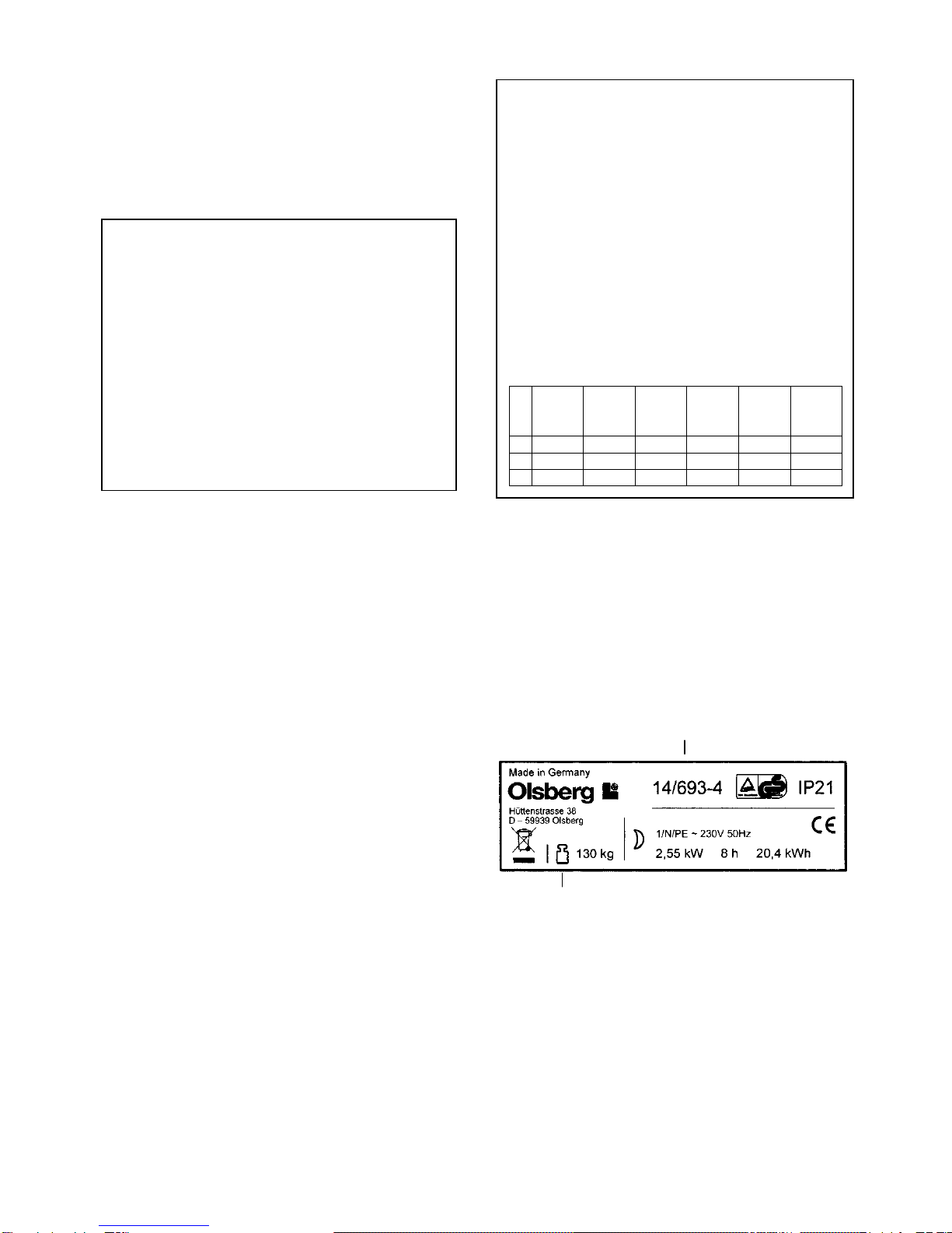
-The electrical installer must measure the power
draw of the elements. This can be done using a
kW and time measurement or alternatively by
measuring the cold element resistance. The
value is to be compared with that of the rating la-
bel or in the ‘Technical Data’ Section.
•The storage heater is only to be used in rooms
where neither explosive gases (e.g. from floor-
sealant), nor inflammable dust is present!
•Electrical appliances conform to valid safety regu-
lations. Repairs and service to electrical appliances
must only be carried out by a competent electri-
cian. Improper repair can mean distinct danger to
the user.
•As the surfaces of the heater cabinet get hot in
use, flammable or other objects presenting a dan-
ger of fire must not be placed on, or near the
heater.
Do not, therefore, place any wooden objects,
clothes or washing, newspapers, blankets or the
like on or over the heater and do not put any
pieces of furniture made of inflammable materials,
nor spray tubes or similar objects closer than 25cm
in front of, or on the heater, especially not in front
of the air-outlet grille.
•It is important to remember that the surfaces of the
heater can reach temperatures in excess of 80°C
(60K) during operation.
•The storage heater is designed to need very little
maintenance.
•Cleaning and maintenance intervals are very de-
pendent on the respective circumstances sur-
rounding installation and operation. We recom-
mend that the first inspection take place at the lat-
est before the second heating period. Further
maintenance intervals can then be set according to
individual circumstances.
•Heater surfaces must not be cleaned with any
scouring or soft-scrub materials. Only use normal
household cleaning liquids.
•Heaters that have already been in operation or
have been taken apart and repositioned must be
re-installed according to these instructions. The
commissioning tests described on this page must
also be carried out.
-any insulation parts which are, or seem to be,
damaged or have changed properties which
could influence their function and safety, must
be replaced by new ones.
•Packaging materials, replaced parts and decom-
missioned appliances and/or parts must be dis-
posed of correctly.
•This heater is not intended for operating by per-
sons (including children), with reduced physical,
sensory or mental abilities or for lack of experience
and/or for lack of knowledge to be used it by a per-
son responsible for their security is supervised or
received from instructions like the heater to use.
Children should be supervised, in order to guaran-
tee that they do not play with the heater.

28
Operation
•General
We thank you for purchasing one of our heaters. It
was manufactured in a modern production facility.
An elegant form, simple operation, excellent heat-
ing performance and reliability are the main fea-
tures of this appliance.
An electric storage heater is an appliance which
draws electricity during the OFF-PEAK period and
converts it into heat which is stored and then dissi-
pated gradually into the room to be heated, de-
pending on the heat load of that area.
If the heater is sized correctly it will store just
enough heat to keep the room satisfactorily warm.
It is of course an advantage if the dwelling is well
insulated as this helps save heating costs. If, for
any reason, the heater installation does not work
satisfactorily, our after-sales service engineers can
check out the system and correct possible prob-
lems.
•Please note the section ‘Important instructions
for installation and operation’ when commis-
sioning, using, cleaning, repairing or reposi-
tioning this heater.
•Do not cover
This heater must not be covered!
All appliances carry a ‘DO NOT COVER’ label on
the top panel which should act as a reminder.
•Major components
- Storage core (1):
The storage core bricks are made of a refractory
material which can reach a temperature of more
than 700°C at full heater charge.
- Heat insulation:
The heat insulation allows a continuous and
gradual dissipation of the core heat into the room.
The following materials are used:
∗Microtherm-G (2) at core front and rear
∗Mineral wool (3) at the rear and in the left and
right panels
∗Vermiculite (4) in the support and upper part
of the core
- Sheathed heating elements (5):
heat resistant steel 1.4828
- Control, regulation and safety components
which monitor the charge and discharge.
- Cabinet
stove-enamelled steel plate.
- Feet
pressed steel plate, powder coated or painted.
fig.27
•Operation
The heater operates without noise. The only me-
chanically moving part is the air mixing plate
(d, fig. 28). The thermal expansion of the core is
absorbed by the insulation.
The heat dissipation into the room takes place to
80% via natural convection, whereas 20% is radi-
ated into the room from the heater surfaces.
The convection processes cause an air-stream
from the surfaces of the heater into the upper lay-
ers of the room. Colder air masses are displaced,
causing a hardly noticeable air circulation which al-
lows for a gradual and even heating of the room.

29
fig.28
•Charging
Series Static Storage Heater have three models:
∗manual: 14/69_-3
∗automatic: 14/69_-4
∗intelligent: 14/70_-3
- Charging of manual heaters,
Model 14/69_-3
The adjustment of the charge takes place using
the operating knobs on the top right of the heater
(e, fig.29).
The manual Model 14/69_-3 appliances are fitted
with a thermo-mechanical regulator, which moni-
tors the heater charge according to the core tem-
perature. The residual heat left in the core from
the previous day is continuously taken into ac-
count. An additional temperature safety control is
fitted as a separate safety element.
The charge can be adjusted continuously from
zero (control knob fully anticlockwise) to full
charge (control knob fully clockwise “max.“). The
charge control switches off the elements auto-
matically on reaching the set charge.
The “max.“ adjustment should only be used on
the coldest days. The setting best suited to the
ambient conditions is ideally found by trial and er-
ror.
- Charging of automatic heaters,
Model 14/69_-4
The adjustment of the charge takes place using
the operating knobs on the top right of the heater
(e, fig.29).
The automatic Model 14/69_-4 appliances are fit-
ted with a thermo-mechanical regulator, which
monitors the heater charge up to 90% in relation
to the room temperature. The other 10% is influ-
enced by the temperature of the storage core.
The room temperature sensor is mounted inside
the front right of the heater cabinet. The tempera-
ture at this point is in close correlation to the am-
bient temperature.
Two additional temperature safety controls are fit-
ted as separate safety elements.
The charge can be adjusted continuously from
zero (control knob fully anticlockwise) to full
charge (control knob fully clockwise “max.“). The
charge control switches off the elements auto-
matically on reaching the set charge. Setting the
adjustment knob ’e’ in fig. 29 to the end of the
‘comet tail’ will cause the heater only to charge at
temperatures below 5°C (frost protection setting).
The setting best suited to the ambient conditions
can best be found by trial and error. We recom-
mend measuring the room temperature on differ-
ent days at different adjustment settings to find
the best setting suited to the ambient conditions.
fig.29
•Manual reset cut-out
All storage heaters are fitted with a manual reset
cut-out, which will isolate the appliance in the event
of a fault occurring causing the heater to overheat.
This device must be reset by a competent electri-
cian, and the appliance inspected to determine the
reason for operation of the control.
Possible faults:
- Defective charge control regulator B1.
-Appliance has been draped/covered causing heat
stagnation.

30
- Static Storage Heater intelligent,
Model 14/70_-3
The charge control registers the outside tempera-
ture and converts this value into a control current.
This current is passed via the control wires A1/Z1
and A2/Z2 to the control resistance in each stor-
age heater.
At the same time, the temperature in the heater
core is also registered. The switch-off point of the
charge thermostat is therefore determined by
both the outside temperature and the tempera-
ture of the heater core.
In this way, a control of charge according to the
outside temperature and the residual heat in the
heater is achieved, thus complying with Energy
Saving Legislation.
The control wires can be run together with cable
feeds L, N and PE.
Please also read the Instruction Leaflet supplied
with the Charge Control.
•Discharge
(all heaters except Model 14/691)
As already explained in section ‘Operation’, ap-
proximately 80% of the stored heat is dissipated
into the room via convection through the three
channels made for this purpose.
In fig.28 the front channel is shown as ’a’, the rear
channel as ’b’ and the middle channel as ’c’. The
air flow through the middle channel ’c’ is controlled
by the flap ’d’. This flap is adjusted using the left
control element ’f’ on the upper right hand side of
the heater (fig. 29). It is continuously adjustable
from “0“ (fully counter-clockwise) to “max.“ (fully
clockwise).
This discharge control enables the heat dissipation
via the air flow through the middle channel ’c’ to be
regulated by means of naturally boosting or thrott-
ling the convection.
fig.27 shows the flap ’d’ in the closed, fig.28 in the
open position.
Discharge can be classified in two distinct meth-
ods:
- Manual Discharge
In position “0“ (fully counter-clockwise, start of the
comet tail) the flap will not open at all, regardless
of the ambient conditions and the state of the
storage core.
If an increased heat dissipation into the room is
desired, for instance at the start of the evening,
the control mechanism must have a higher set-
ting, so that the flap can open.
- Automatic Discharge
With the control element ’f’ at setting “max.“ (see
fig.29), the air flap opens according to the resid-
ual heat left in the storage core. If the core is still
fully charged the flap remains closed, even if the
control element is set at “max.“.
If the control element is adjusted to a certain set-
ting, the flap opens automatically as soon as the
corresponding level of heat dissipation has been
reached, e.g.:
∗setting in middle position - the flap opens at
the beginning of the evening
∗“max.“ setting, the flap opens early afternoon
NB: Heater 14/691 has no discharge control.
Heat dissipation via convection takes place
only in the front and rear channels (’a’ and
’b’ in fig.28).
•Commissioning
Set charge and discharge adjusters to the “max.“
position and leave them in this position for 48
hours (i.e. 2 charging cycles).
Due to manufacturing techniques, a part of the
heater insulation contains some binding agents
which can cause unpleasant odours during the first
charging. Any dust or machine oils which have col-
lected on the surface of, for instance, the heating
elements will also burn off, causing possible
odours.
It is thus vitally important that the room(s) be well
ventilated during the first 48 hours or 2 charge cy-
cles!
NB: Model 14/691 has no discharge control ele-
ment.

31
Removing the control unit for servicing
•The control unit can be easily removed in one
piece for servicing work.
This is done as follows:
- Remove front panel of heater.
- Remove right side panel if necessary.
- Open the plastic adjustment element cover
(fig.30).
- Pull off the adjustment knobs (fig.30).
- Remove the front retaining screws left and right
(fig.30 and fig.31).
- Pull the control unit forward and out (fig.32 and
fig.33).
•Refitting takes place in the opposite manner.
•Make sure that:
- the fluid regulator capillary tube is not bent or
damaged.
- the connecting cables are not damaged.
- the bimetal-strip is not bent or deformed.
- the control unit slots onto the flaps in the rear
panel, made for this purpose.
fig.30
fig.31
fig.32
fig.33

32
Circuit diagram
•manual: 14/691-3, 14/692-3, 14/693-3, 14/694-3, 14/695-3 2) 78/4514.4923

33
•automatic: 14/692-4, 14/693-4, 14/694-4, 14/696-4 2) 78/4514.4924

34
•intelligent: 14/702-3, 14/703-3, 14/704-3 1) 78/4514.7023

84
10) 78/4614.6913 02/2011
Olsberg GmbH
Hüttenstraße 38
59939 Olsberg
T +49 2962 805-0
F +49 2962 805-180
olsberg.com
This manual suits for next models
11
Table of contents
Other Olsberg Heater manuals

Olsberg
Olsberg Confort User manual

Olsberg
Olsberg Orayonne User manual

Olsberg
Olsberg CTSC User manual

Olsberg
Olsberg Noblesse User manual

Olsberg
Olsberg 14/512 User manual

Olsberg
Olsberg Corona Series User manual

Olsberg
Olsberg AirCom Zentral User manual

Olsberg
Olsberg Orayonne plus User manual

Olsberg
Olsberg 14/71*-3 Series User manual