ADInstruments AD2811 User manual

1
AD INSTRUMENTS
MEDIDOR DE IMPEDANCIA DE BUCLE AD2811.
Manual de instrucciones

2
Índice
Índice..................................................................... 2
Precauciones de seguridad......................................... 3
Especificaciones................................................... 3
Notas de seguridad.......................................................... 3
Características...................................................... 3
Conexiones........................................................... 4
Diseño del equipo ……………………………………....... 4
Funciones.............................................................. 5
Preparación para la Medición................................. 5
Prueba de bucle / PSC / Tierra ........................... 6
Batería................................................................... 7
Calibración y Mantenimiento ................................... 7

3
1. Precauciones de Seguridad
La electricidad puede causar lesiones graves, incluso con bajas tensiones o corrientes. Por lo tanto, es
extremadamente importante que lea la siguiente información antes de utilizar el equipo.
1.1 Este instrumento sólo debe ser aplicado y utilizado por una persona competente, formado y con estricto seguimiento
de las instrucciones.
No aceptaremos responsabilidad por cualquier daño o lesión causados por mal uso o incumplimiento de instrucciones
y de seguridad. Este instrumento inyecta una alta corriente dentro de la Tierra.
1.2 Este instrumento sólo se diseñó para el funcionamiento monofásico, 230Vac ± 20% Con la correcto cableado (Fase,
Neutro y Tierra). Nunca se debe conectar entre fases pues puede provocar daños. Cuando se realiza una prueba, no
toque las piezas metálicas expuestas o de las partes conductoras.
1.3 Todas la s p r o t e c c i o nes R C C B , GFC I y E L C B e n e l circuito a pr u e b a d e ben s e r evitadas durante la duración de la
prueba.
1.4 Nunca abra el equipo, a excepción de reemplazo de la batería. (Ver la sección de reemplazo de bateria).
1.5 Antes de usarlo, siempre inspeccione el equipo y los cables de prueba . Si existen condiciones anormales (cables de
prueba rotos, cuerpo agrietado, etc ...) No intente tomar ninguna medición o utilizar el probador.
1.6 El AD2811 ha sido diseñado para su seguridad. Sin embargo, no hay diseño puede proteger completamente contra
usos incorrectos . Los circuitos eléctricos pueden ser peligrosos y / o letales. Tenga precaución en presencia de
tensión por encima de 24V ya que estos representan un peligro de choque.
1.7 Preste atención a las precauciones y advertencias que le informará de potencialmente peligrosos procedimientos.
2. Especificaciones
Rangos de medida
0,01-2000ΩRango automático
Corriente PSC (L-N)
0-3KA
Te n s i ó n d e f u n c i o n a m i e n t o
50-275Vac (50 o 60 Hz)
Te n s i ó n n o m i n a l i d e a l
230Vac ± 20% Max10A
Te m p e r a tu r a d e
funcionamiento
0° C-40° C
Te m p e ratura de
almacenamiento
-20 ° C-60° C
Humedad de funcionamiento
85% de humedad relativa máxima
Humedad de almacenamiento
85% de humedad relativa máxima
Precisión de voltajes
±1% (210-250V)
±3% de otro modo
Precisión Bucle / Tierra y
Impedancias cables
±3% (0.05-500Ω)
±15% (por encima 500Ω)
Fuente de energía
8x pilas AA
3. Notas de seguridad
Condiciones ambientales :
(1) Uso de interior
(2) Categoría de instalación II.
(3) El grado de contaminación 2.
(4) Altitud de hasta 2000 metros.
(5) Humedad Relativa 85% Max.
(6) Te m p e r a t ura ambiente 0° C -40° C
Observe los siguiente símbolos eléctricos internacionales:
Advertencia! Riesgo de descarga eléctrica
¡Precaución! Consulte este manual antes de usar el medidor.
4. Características
●2líneas x 16 caracteres
●Rango automático / apagado automático
●Operación con un solo pulsador
●Muy Bajo Consumo
●Controlado por microprocesador
●Precision mejor que 3% (0.05-50Ω)
●Integridad del Cableado (pantalla + LED)
●Proteccion de sobrecalentamiento
●Almacena las lecturas
●Medidas:
Tensiones L-E y L-N

4
L-E y L-N Impedancia de lazo
Cortocircuitos prospectivos L-E y L-N
Espiga de Tierra , Linea e Impedancia del neutro
5. Conexiones
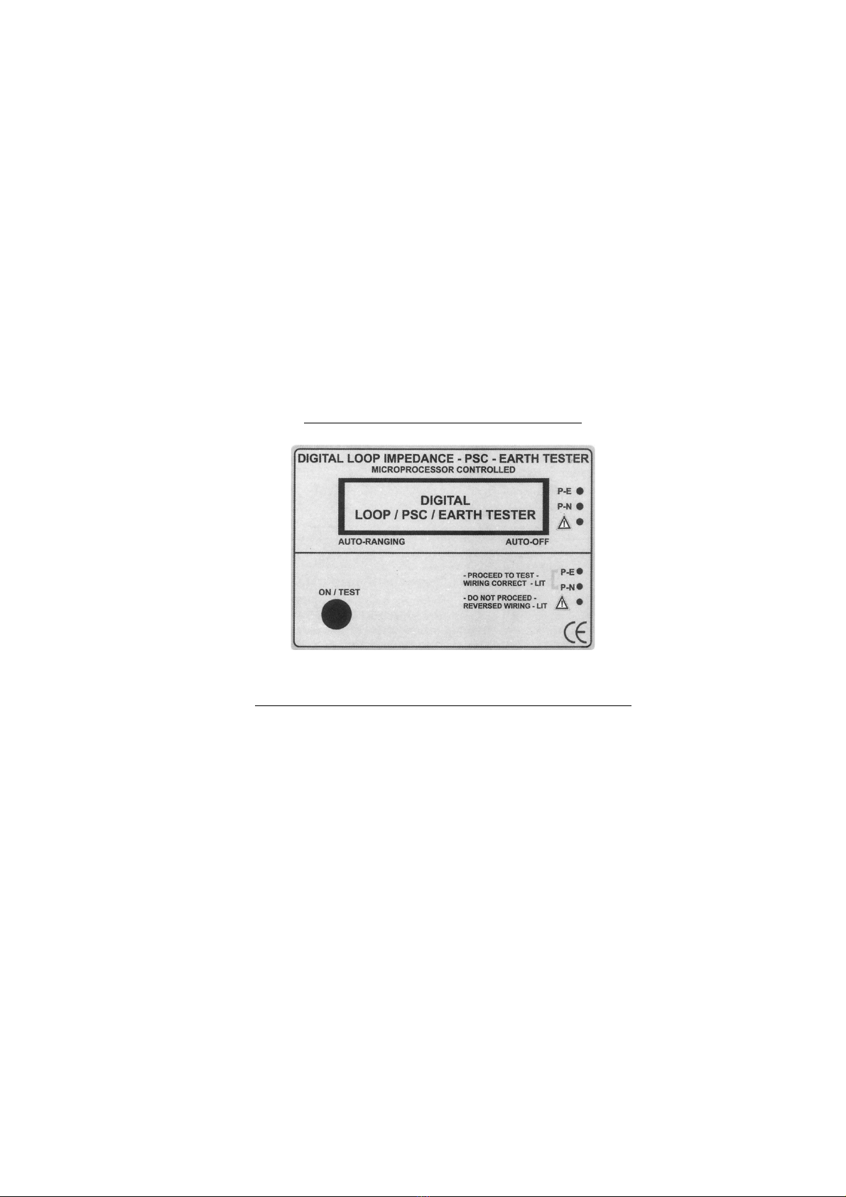
6. Diseño del equipo
1- On.
Prueba
Scroll / Seleccione Menú
2- Pantalla LCD.
3- Leds indicadores del Cableado

5
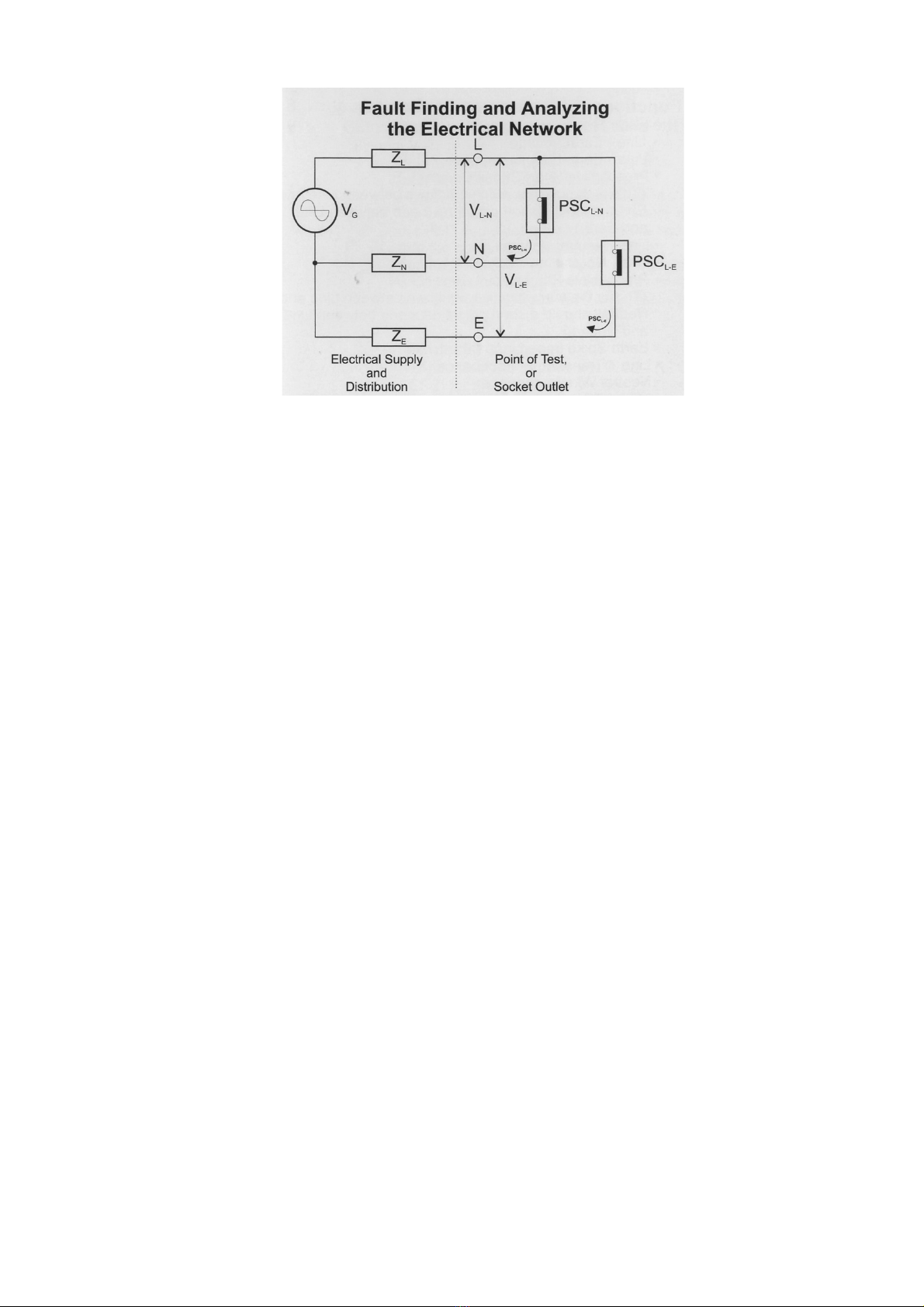
VG = Tensión del generador (transformador de alimentación)
(Impedancia interna del transformador = X-Form)
ZL = Impedancia del cable de red desde el transformador hasta el punto de prueba (ZL mostrada por el equipo también
incluye X-Form). Si esta impedancia es demasiado alta, compruebe las conexiones del cableado de la línea,
compruebe la calidad del cableado de la línea y los interruptores / contactos en el circuito de línea.
ZN = Impedancia del cable neutro del transformador, hasta el punto de prueba. Si esta impedancia es demasiado alta,
compruebe las conexiones del Neutro, comprobar la calidad de la línea de cableado y los interruptores o contactos en
el circuito neutral.
ZE = Impedancia del cable de la Tierra, incluyendo la impedancia de la Tierra en sí misma, como se ve por el sistema de
protección. Comprobaciónes similares, especialmente en los puntos de delimitación, debe hacerse si esta impedancia
es demasiado alta.
7. Funciones
Medidas del equipo:
●Te n s i o n Línea –Tierra
●Impedancia de bucle Línea -Tierra.
●Probable Intensidad de Cortocircuito L-E.
(Esta es la corriente que fluye entre la línea y la Tierra,
se debe hacer un cortocircuito entre la línea y la Tierra)
●Te n s i o n L í n e a -Neutro
●Impedancia Linea-Neutral
●Probable Intensidad de Cortocircuito L -N.
(Esta es la corriente que se fluye entre línea y neutro,
se debe hacer un cortocircuito entre la línea y neutro)
●Impedancia de la Tierra (cable de tierra)
●Impedancia Linea+ transformador(X-Form)
●Impedancia del cable neutro
●Integridad de cableado
Informes de prueba :
●Indicador de batería baja
●Mal cableado
●No hay línea
●Sobrecalentamiento
8. Preparación para la medición
Antes de la prueba, controle siempre lo siguiente.
●Tensión del Sistema
El AD2811 esta diseñado para funcionar con 230 Vac. Sin embargo, si la tensión es menor, la prueba todavia se puede
hacer pero la precisión podría deteriorarse debido al hecho de que la corriente inyectada es inferior a la óptima. Sin
embargo, el equipo puede trabajar en una amplia gama de tensión y de cómputo para que esos cambios tengan un
efecto mínimo en los resultados.
●ELCB / RCCB / GFCI
Es necesario evitar los interruptores automaticos y diferenciales durante la duracion de la pruebas.

6
Utilice conductores de mismo tamaño que el circuito RFT.
●Desenchufe todas las cargas
A fin de no afectar a la medición, se han de desconectar toda la carga de la instalación bajo prueba.
●Hacer un esquema claro de la medición para poder interpretar resultados.
●Compruebe los conductores antes de usar el equipo..
La calidad de las cargas y Resistencia es un factor de influencia en la exactitud de los resultados. Asegúrese de que
siempre están en buenas condiciones.
9. Prueba de bucle / PSC / Tierra
Encienda el instrumento pulsando "ON / TEST. La pantalla LCD mostrara lo siguiente:
Pulse "ON / Prueba" Ahora comenzará la prueba. Este procedimiento es totalmente automatic
El Voltaje principal se indica la tensión entre L –N
Desde este primer resultado, puede desplazarse a través de los resultados de las pruebas con el botón de prueba.
Desplácese por los resultados de nuevo si el equipono está conectado al circuito bajo prueba o haga
una nueva prueba conectando el equipo al circuito bajo prueba.
Si el circuito bajo prueba esta en circuito abierto, la pantalla mostrará "NO LINEA".

7
10. Batería
Reemplazo de la batería
●El equipo supervisa continuamente el voltaje de la batería y indica cuando la batería necesita ser reemplazado.
●Las baterías están situadas en el inferior del equipo.
●Desconecte los cables de prueba del instrumento, retire la tapa de las pilas y las baterías
●Reemplazar con ocho pilas AA 1,5 V, teniendo cuidado de respetar la polaridad correcta.
●Se recomienda utilizar pilas alcalinas.
●Vuelva a colocar la cubierta de las baterias
11. Calibración y Mantenimiento
Ambos, la calibración y el mantenimiento deben ser realizados por personal competente entrenado.
Póngase en contacto con su distribuidor autorizado más cercano sobre el certificado de calibración y mantenimiento.
Antes de devolver el instrumento, asegúrese de que:
●Se ha comprobado la continuidad de los cable y no hay signos de daño.
●las baterías están en buen estado
●Limpieza y almacenamiento:
ADVERTENCIA
Para evitar descargas eléctricas o daños al medidor, no introducir agua en el caso.
Limpie periódicamente la caja con un paño húmedo y detergente; no utilice abrasivos o solventes.
Si el medidor no es usado durante periodos mayores a 60 días, retire las pilas y guardarlas por separado.
Distribuido por:
8
AD INSTRUMENTS
Hand Held
Electrical Network Analyzer and Fault
Finding Instrument.
Instruction Manual
DIGITAL “MULTIPLE”LOOP / PSC / EARTH TESTER

9
Index
Index………………………………………………….. 9
Safety Precautions…………..……………………… 10
Specifications………………………………………… 10
Safety Notes…………………………………………. 10
Features……………………………………………… 10
Connections………………………………………….. 11
Instrument Layout and System Connections……. 11
Functions……………………………………………... 12
Preparation for Measurement………………………. 13
Loop / PSC / Earth testing ……………………….. 14
Battery……………………………….……………….. 14
Calibration & Servicing …………..………………… 14
10
1. Safety Precautions
Electricity can cause severe injuries,even with low voltages or currents. Therefore,it is extremely important that you
read the following information before using your Digital Psc-Loop-Earth Te s t e r and Electrical Network Analyzer.
1.1 This Instrument must only be used and operated by a competent trained person and in strict accordance with the
instructions.
We will not accept liability for any damage or injury caused by misuse or non compliance with instructions and safety.
Procedures this instrument inject a High Current into the Earth.
1.2 This instrument is only intended for Single Phase operation, 230Vac±20% with the correct wiring (Phase, Neutral and
Earth). It must never be connected Phase to Phase. Damages could result. When Conducting a test, do not touch any
exposed metal parts or any conducting parts.
1.3 All RCCB, GFCI and ELCB in the circuit to test must be bypassed ONLY for the duration of the test.
1.4 Never open the Tester, except for battery replacement. ( See Battery replacement section ).
1.5 Before use, always inspect the tester and test leads for any sign of abnormal condition or damage. If any abnormal
conditions exist (broken test leads, cracked case, display faulty etc…) do not attempt to take any measurement or use
the tester. Return it to nearest Distributor for Service.
1.6 The tester has been designed with your safety in mind. However, no design can completely protect against incorrect
use. Electrical circuits can be dangerous and/or lethal when a lack of caution or poor safety practice is used. Use
caution in the presence of voltage above 24V as these pose a shock hazard.
1.7 Pay attention to cautions and warnings which will inform you of potentially dangerous procedures.
2.Specifications
Loops / Earth / Wires
0.01-2000ΩAuto-ranging
Prospective Short Circuit
0-3KA
Operating Voltage
50-275Vac (50 or 60 Hz)
Best Performance at Rated Voltage
230Vac±20% Max10A
Operating Temperature
0°C-40°C
Storage Temperature
-20°C-60°C
Operating Humidity
85%RH Maximum
Storage Humidity
85%RH Maximum
Accuracy of Voltages
±1% (210-250V)
±3% otherwise
Accuracy Loops/Earth And Wires Impedances
±3% (0.05-500Ω)
±15% (above 500Ω)
Power Source
8 x AA battery
3.Safety Notes
Rated environmental conditions:
(7) Indoor use
(8) Installation Category II.
(9) Pollution Degree 2.
(10) Altitude up to 2000 Meters.
(11) Relative Humidity 85% Max.
(12) Ambient Temperature 0°C - 40°C
Observe the International Electrical Symbols listed below:
Warning! Risk of Electric Shock
Caution! Refer to this manual before using the meter.
4.Features
●2 Lines x 16 Characters
●Auto-ranging / Auto-off
●One Push Button Operation
●Very Low Consumption
●Microprocessor Controlled
●Better than 3% Accuracy (0.05-50Ω)
●Wiring Integrity Check (display + LEDs)
●Over Temperature Protection
●Stores Previous readings

11
●Measures: L-E and L-N voltages
L-E and L-N Loop Impedance
Prospective Short Circuits L-E and L-N
Earth Spike, Line and Neutral Impedances
5.Connections
6.Instrument Layout and System Connections
4- On.
Test
Scroll / Menu Select
5- Large, High Contrast L.C.D.
6- High Bright Wiring Check Led’s
12
VG=Voltage of the generator (supply transformer) (internal impedance of transformer = X-Form)
ZL=Impedance of the Line wire from the transformer, up to the test point (ZLdisplayed by Instrument also include X-Form). If
this impedance is too high, check the connections of the Line wiring, check the quality of the line wiring and the
switches / contacts in the line circuit.
ZN=Impedance of the Neutral wire from the transformer, up to the
test point. If this impedance is too high, check the connections of the Neutral wiring, check the quality of the line wiring
and the switches or contacts in the Neutral circuit.
ZE=Impedance of the Earth wire, including the Earth Impedance itself, as seen by the protection system. Similar checking,
specially at the bounding points should be done is this path impedance is too high.
7.Functions
The tester Measures:
●Line – Earth Voltage
●Line – Earth Loop Impedance.
●Prospective Short Circuit Current L– E.
(This is the current which will flows between Line and Earth,
should a short circuit be made between Line and Earth)
●Line – Neutral Voltage
●Line – Neutral Impedance
●Prospective Short Circuit Current L – N.
(This is the current which will flows between Line and Neutral,
should a short circuit be made between Line and Neutral)
●Earth Spike Impedance (Earth Wire)
●Line + Transformer Impedance (X-Form)
●Neutral Wire Impedance
●Wiring Integrity
The tester report:
●Low battery indication
●Bad wiring
●No line
●Over-Temperature
8.Preparation for measurement
Before testing Always check the following.
●System Voltage
Your Digital Psc / Loop / Earth Tester is best intended to work with 230 Vac. However, if the voltage is lower than that,
the test could still be done but accuracy of the PSC could deteriorate due to the fact that the current injected is lower
than optimal. However, your tester can work on a wide range of voltage and compute results so that those changes
have a minimal effect on Results.
●ELCB / RCCB / GFCI
It is necessary to bypass the ELCB / RCCB / GFCI for the duration of the Earth / Loop / Psc test. Use Leads of same
size as ELCB circuit.

13
●Unplug all Load
In order not to affect the measurement, it is avoided to unplug all load from the installation under test.
●Make a clear Sketch of measurement to be able to Interpret results.
●Check leads before using Tester.
The Leads Quality and Resistance is a factor influence the accuracy of the results make sure they are always in good
conditions.
9.Loop / PSC / Earth testing
Turn Instrument ON by pressing “ON / TEST”. The L.C.D. display will come to the following Screen
Pressing “ON / Test”now will start the test. This Testing procedureis fully Automatic and Controlled by the Micro Processor
Main Voltage is indicating the voltage between L – N
From this first results, you can scroll through the test results using the Test button.
Scroll through the results again, if the tester is not connected to the circuit under test or do a new test by connecting the
tester to the circuit under test.
If the circuit under test is open-circuit, the display will show “NO LINE”.

14
10.Battery
Battery Replacement
●The Tester continuously monitors the battery voltage and indicates when the battery need to be replaced.
●The tester’s batteries are situated under the test.
●Disconnect the test leads from the instrument, remove the battery cover and the batteries
●Replace with eight 1.5V AA pen light batteries, taking care to observe correct polarity.
●Alkaline batteries are recommended.
●Replace battery Holder and the battery cover
11.Calibration & Servicing
Both, calibration and servicing must be performed by a competent trained and approved person.
Contact your nearest authorized distributor about Calibration Certificate and Servicing.
Before returning the Instrument, ensure that:
●the leads have been checked for continuity and signs of damage.
●the batteries are in good condition
●Cleaning and storage:
WARNING
To avoid electrical shock or damage to the meter, do not get water inside the case.
Periodically wipe the case with a damp cloth and detergent; do not use abrasive or solvents.
If the meter is not to used for periods of longer than 60 days, remove the batteries and store them separately.
Distributed by:
Other manuals for AD2811
1
Table of contents
Languages:
Other ADInstruments Test Equipment manuals


Popular Test Equipment manuals by other brands


Bacharach
Bacharach Tru Pointe Ultra Operation and maintenance guide

Ransburg
Ransburg 76652-01 Service manual

Kyoritsu Electrical Instruments Works, Ltd.
Kyoritsu Electrical Instruments Works, Ltd. 4200 instruction manual

Power Probe
Power Probe INT500 user manual

EMIT
EMIT SmartLog V5 Installation, operation and maintenance

Promax
Promax PE-005 manual


