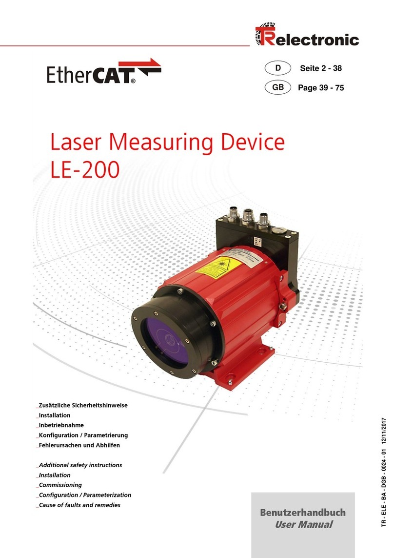
TR-Electronic LE-200 User manual

TR - ELE - BA - GB - 0010 - 10 12/08/2017
User Manual
_Additional safety instructions
_Installation
_Commissioning
_Configuration / Parameterization
_Troubleshooting / Diagnostic options
Laser Measuring Device
LE-200

TR-Electronic GmbH 2007, All Rights Reserved Printed in the Federal Republic of Germany
Page 2 of 47 TR - ELE - BA - GB - 0010 - 10 12/08/2017
TR-Electronic GmbH
D-78647 Trossingen
Eglishalde 6
Tel.: (0049) 07425/228-0
Fax: (0049) 07425/228-33
email: info@tr-electronic.de
www.tr-electronic.de
Copyright protection
This Manual, including the illustrations contained therein, is subject to copyright
protection. Use of this Manual by third parties in contravention of copyright
regulations is not permitted. Reproduction, translation as well as electronic and
photographic archiving and modification require the written content of the
manufacturer. Violations shall be subject to claims for damages.
Subject to modifications
The right to make any changes in the interest of technical progress is reserved.
Document information
Release date / Rev. date: 12/08/2017
Document / Rev. no.: TR - ELE - BA - GB - 0010 - 10
File name: TR-ELE-BA-GB-0010-10.docx
Author: MÜJ
Font styles
Italic or bold font styles are used for the title of a document or are used for
highlighting.
Courier font displays text, which is visible on the display or screen and software
menu selections.
< > indicates keys on your computer keyboard (such as <RETURN>).
Brand names
CANopenand CiAare registered community trademarks of CAN in Automation e.V.

Printed in the Federal Republic of Germany TR-Electronic GmbH 2007, All Rights Reserved
12/08/2017 TR - ELE - BA - GB - 0010 - 10 Page 3 of 47
Contents
Contents.............................................................................................................................................. 3
Revision index .................................................................................................................................... 6
1 General information ........................................................................................................................ 7
1.1 Applicability............................................................................................................................. 7
1.2 References.............................................................................................................................. 8
1.3 Abbreviations and definitions.................................................................................................. 9
2 Additional safety instructions........................................................................................................ 10
2.1 Definition of symbols and instructions .................................................................................... 10
2.2 Additional instructions for proper use ..................................................................................... 10
2.3 Organizational measures........................................................................................................ 11
3 CANopen information’s .................................................................................................................. 12
3.1 CANopen –Communication profile ........................................................................................ 13
3.2 Process- and Service-Data-Objects ....................................................................................... 14
3.3 Object Dictionary .................................................................................................................... 15
3.4 CANopen default identifier...................................................................................................... 15
3.5 Network management............................................................................................................. 16
3.6 Device profile.......................................................................................................................... 17
4 Installation / Preparation for start-up............................................................................................ 18
4.1 Electrical connection............................................................................................................... 19
4.1.1 Supply voltage ........................................................................................................ 19
4.1.2 CANopen................................................................................................................. 19
4.2 Bus termination....................................................................................................................... 20
4.3 DIP-switch –settings .............................................................................................................. 20
4.3.1 Identifier (Node-ID) ................................................................................................. 20
4.3.2 Baud rate................................................................................................................. 20
4.4 Switching input / Switching output.......................................................................................... 21
4.5 RS485 - programming interface.............................................................................................. 21
4.6 Wiring examples ..................................................................................................................... 22
4.7 General interference suppression measures.......................................................................... 23
4.8 Switching on the supply voltage ............................................................................................. 23
5 Commissioning................................................................................................................................ 24
5.1 CANopen interface ................................................................................................................. 24
5.1.1 EDS-file................................................................................................................... 24
5.1.2 Bus status ............................................................................................................... 25

Contents
TR-Electronic GmbH 2007, All Rights Reserved Printed in the Federal Republic of Germany
Page 4 of 47 TR - ELE - BA - GB - 0010 - 10 12/08/2017
6 Communication profile ................................................................................................................... 26
6.1 Transmitting of the position value........................................................................................... 26
6.1.1 1st Transmit Process Data Object (asynchronous)................................................. 27
6.1.2 2nd Transmit Process Data Object (synchronous) .................................................. 27
6.2 Read/Write Service Data Object............................................................................................. 28
6.2.1 Read SDO:.............................................................................................................. 28
6.2.2 Write SDO:.............................................................................................................. 29
7 Communication specific standard objects................................................................................... 30
7.1 Object 1000h: Device Type .................................................................................................... 31
7.2 Object 1001h: Error Register.................................................................................................. 31
7.3 Object 1002h: Manufacturer Status Register ......................................................................... 31
7.4 Object 1003h: Pre-defined Error Field.................................................................................... 32
7.5 Object 1004h: Number of PDOs supported............................................................................ 33
7.6 Object 1005h: COB-ID SYNC message................................................................................. 33
7.7 Object 1008h: Manufacturer Device Name ............................................................................ 34
7.8 Object 1009h: Manufacturer Hardware Version..................................................................... 34
7.9 Object 100Ah: Manufacturer Software Version ...................................................................... 34
7.10 Object 100Bh: Node-ID......................................................................................................... 34
7.11 Object 100Ch: Guard-Time................................................................................................... 34
7.12 Object 100Dh: Life Time Factor............................................................................................ 35
7.13 Object 100Eh: Node Guarding Identifier............................................................................... 35
7.14 Object 1010h: Store Parameters.......................................................................................... 35
8 Parameterization and configuration.............................................................................................. 37
8.1 Standardized encoder profile area ......................................................................................... 37
8.1.1 Object 2000 –Clear Preset..................................................................................... 38
8.1.2 Object 2001 –Output value in case of an error...................................................... 38
8.1.3 Object 2003 –Function external input.................................................................... 39
8.1.4 Object 2004 –Automatic error acknowledgement.................................................... 39
8.1.5 Object 2005 –Function error output....................................................................... 39
8.1.6 Object 2006 –Switching functions.......................................................................... 40
8.1.7 Object 2007 –Resolution........................................................................................ 40
8.1.8 Object 6000h –Operating parameters ................................................................... 41
8.1.9 Object 6003h –Preset value .................................................................................. 41
8.1.10 Object 6004h –Position value.............................................................................. 42
8.1.11 Object 6005h –Measuring step............................................................................ 42
8.1.12 Object 6200h –Cyclic timer.................................................................................. 42
8.2 Laser diagnostics.................................................................................................................... 43
8.2.1 Object 6500h - Operating status............................................................................. 43
8.2.2 Object 6501h –Measuring step.............................................................................. 43
8.2.3 Object 6503h - Alarms............................................................................................ 43
8.2.4 Object 6504h - Supported alarms........................................................................... 44
8.2.5 Object 6505h - Warnings........................................................................................ 44
8.2.6 Object 6506h - Supported warnings ....................................................................... 45

Printed in the Federal Republic of Germany TR-Electronic GmbH 2007, All Rights Reserved
12/08/2017 TR - ELE - BA - GB - 0010 - 10 Page 5 of 47
8.2.7 Object 6507h –Software version............................................................................ 45
8.2.8 Object 6508h - Operating time................................................................................ 45
8.2.9 Object 6509h - Offset value.................................................................................... 45
8.2.10 Object 650Ah - Manufacturer offset value............................................................ 45
8.2.11 Object 650Bh - Serial number .............................................................................. 45
9 Emergency Message....................................................................................................................... 46
10 Causes of Faults and Remedies .................................................................................................. 47
Appendix:
Pin Assignment downloads:
Screw clamps...........................................................www.tr-electronic.com/f/TR-ELE-TI-GB-0010
Similar to CiA DR 303-1........................................www.tr-electronic.com/f/TR-ELE-TI-DGB-0011
Conform to CiA DR 303-1.....................................www.tr-electronic.com/f/TR-ELE-TI-DGB-0016
2 x M12.................................................................www.tr-electronic.com/f/TR-ELE-TI-DGB-0017
Drawing downloads:
Dimensioned drawing (cable outlet) ..................................www.tr-electronic.com/f/04-K2200-002
Dimensioned drawing (M12 connector).............................www.tr-electronic.com/f/04-K2200-012

Revision index
TR-Electronic GmbH 2007, All Rights Reserved Printed in the Federal Republic of Germany
Page 6 of 47 TR - ELE - BA - GB - 0010 - 10 12/08/2017
Revision index
Revision
Date
Index
First release
07/24/03
00
Expansion of the function for the error output, object 2005
Speed-check, configurable via TRWinProg
09/19/03
01
New Object: 2007, Resolution
Revision of the warning label
12/11/03
02
Modification of the Laser Standard DIN EN 60825-1
Warning bit “Plausibility measured value”
Additional reflector foils, max. measuring range 240 m
12/18/07
03
Implementation of new reflectors
Physical resolution = 0,1 mm
02/05/09
04
Shield connection via cable screw glands removed
01/12/10
05
General changes
Modification of the warnings
Mounting removed
03/21/13
06
Wiring edited
CAN_H / CAN_L twisted pair
07/31/14
07
Laser lifetime
02/20/15
08
Reference to Support-DVD removed
02/08/16
09
Technical data removed
12/08/17
10

Printed in the Federal Republic of Germany TR-Electronic GmbH 2007, All Rights Reserved
12/08/2017 TR - ELE - BA - GB - 0010 - 10 Page 7 of 47
1 General information
The User Manual includes the following topics:
Safety instructions in additional to the basic safety instructions defined in the
Assembly Instructions
Installation
Commissioning
Configuration / parameterization
Causes of faults and remedies
As the documentation is arranged in a modular structure, this User Manual is
supplementary to other documentation, such as product datasheets, dimensional
drawings, leaflets and the assembly instructions etc.
The User Manual may be included in the customer's specific delivery package or it
may be requested separately.
1.1 Applicability
This User Manual applies exclusively to the following measuring system models with
CANopen interface:
LE-200
The products are labelled with affixed nameplates and are components of a system.
The following documentation therefore also applies:
see chapter “Other applicable documents” in the Assembly Instructions
www.tr-electronic.de/f/TR-ELE-BA-DGB-0018.

General information
TR-Electronic GmbH 2007, All Rights Reserved Printed in the Federal Republic of Germany
Page 8 of 47 TR - ELE - BA - GB - 0010 - 10 12/08/2017
1.2 References
1.
ISO 11898: Road Vehicles Interchange of Digital Information - Controller Area
Network (CAN) for high-speed Communication, November 1993
2.
Robert Bosch GmbH, CAN Specification 2.0 Part A and B, September 1991
3.
CiA DS-201 V1.1, CAN in the OSI Reference Model, February 1996
4.
CiA DS-202-1 V1.1, CMS Service Specification, February 1996
5.
CiA DS-202-2 V1.1, CMS Protocol Specification, February 1996
6.
CiA DS-202-3 V1.1, CMS Encoding Rules, February 1996
7.
CiA DS-203-1 V1.1, NMT Service Specification, February 1996
8.
CiA DS-203-2 V1.1, NMT Protocol Specification, February 1996
9.
CiA DS-204-1 V1.1, DBT Service Specification, February 1996
10.
CiA DS-204-2 V1.1, DBT Protocol Specification, February 1996
11.
CiA DS-206 V1.1, Recommended Layer Naming Conventions,
February 1996
12.
CiA DS-207 V1.1, Application Layer Naming Conventions, February 1996
13.
CiA DS-301 V4.2, CANopen Communication Profile based on CAL,
December 2007
14
CiA DS-302 V4.1, Additional application layer functions, February 2009
15
CiA DS-303-3 V1.3, Indicator specification, August 2006
16.
CiA DS-305 V2.2.5, Layer Setting Services (LSS) and Protocols,
November 2010
17.
CiA DS-406 V3.2, CANopen Profile for Encoder, December 2006

Printed in the Federal Republic of Germany TR-Electronic GmbH 2007, All Rights Reserved
12/08/2017 TR - ELE - BA - GB - 0010 - 10 Page 9 of 47
1.3 Abbreviations and definitions
LE-200
Laser Measuring Device, LE-200 series
EC
European Community
EMC
Electro Magnetic Compatibility
ESD
Electro Static Discharge
IEC
International Electrotechnical Commission
VDE
German Electrotechnicians Association
CAN specific
CAL
CAN Application Layer. The application layer for CAN-based networks
as specified by CiA in Draft Standard 201 ... 207.
CAN
Controller Area Network. Data link layer protocol for serial
communication as specified in ISO 11898.
CiA
CAN in Automation international manufacturer and user organization
e.V.: non-profit association for Controller Area Network (CAN).
CMS
CAN-based Message Specification. One of the service elements of the
application layer in the CAN Reference Model.
COB
Communication Object. (CAN Message) A unit of transportation in a
CAN Network. Data must be sent across a Network inside a COB.
COB-ID
COB-Identifier. Identifies a COB uniquely in a Network. The identifier
determines the priority of that COB in the MAC sub-layer too.
DBT
Distributor. One of the service elements of the application in the CAN
Reference Model. It is the responsibility of the DBT to distribute
COB-ID´s to the COB´s that are used by CMS.
EDS
Electronic-Data-Sheet
FSA
Finite state automata. State machine to control LSS services.
LSS
Layer Setting Services. Services and protocols for the configuration of the
Node-ID and Baud rate about the CAN Network.
NMT
Network Management. One of the service elements of the application in
the CAN Reference Model. It performs initialization, configuration and
error handling in a CAN network.
PDO
Process Data Object. Object for data exchange between several
devices.
SDO
Service Data Object. Peer to peer communication with access to the
Object Dictionary of a device.

Additional safety instructions
TR-Electronic GmbH 2007, All Rights Reserved Printed in the Federal Republic of Germany
Page 10 of 47 TR - ELE - BA - GB - 0010 - 10 12/08/2017
2 Additional safety instructions
2.1 Definition of symbols and instructions
means that death or serious injury can occur if the required
precautions are not met.
means that minor injuries can occur if the required
precautions are not met.
means that damage to property can occur if the required
precautions are not met.
indicates important information or features and application
tips for the product used.
2.2 Additional instructions for proper use
The measurement system is designed for operation with CANopen networks
according to the International Standard ISO/DIS 11898 and 11519-1 up to max.
1 Mbit/s. The profile corresponds to the "CANopen Device Profile for Encoder CiA
DS-406 V2.0A".
The technical guidelines for the structure of the CANopen network from the CAN User
Organization CiA are always to be observed in order to ensure safe operation.
Proper use also includes:
observing all instructions in this User Manual,
observing the assembly instructions. The "Basic safety instructions" in
particular must be read and understood prior to commencing work.

Printed in the Federal Republic of Germany TR-Electronic GmbH 2007, All Rights Reserved
12/08/2017 TR - ELE - BA - GB - 0010 - 10 Page 11 of 47
2.3 Organizational measures
This User Manual must always kept accessible at the site of operation of the
measurement system.
Prior to commencing work, personnel working with the measurement system
must have read and understood
- the assembly instructions, in particular the chapter "Basic safety
instructions",
- and this User Manual, in particular the chapter "Additional safety
instructions".
This particularly applies for personnel who are only deployed occasionally,
e.g. at the parameterization of the measurement system.

CANopen information’s
TR-Electronic GmbH 2007, All Rights Reserved Printed in the Federal Republic of Germany
Page 12 of 47 TR - ELE - BA - GB - 0010 - 10 12/08/2017
3 CANopen information’s
CANopen was developed by the CiA and is standardized since at the end of 2002 in
the European standard EN 50325-4.
As communication method CANopen uses the layers 1 and 2 of the CAN standard
which was developed originally for the use in road vehicles (ISO 11898-2). In the
automation technology these are extended by the recommendations of the CiA
industry association with regard to the pin assignment and transmission rates.
In the area of the application layer CiA has developed the standard CAL (CAN
Application Layer).
Figure 1: CANopen classified in the ISO/OSI reference model
In case of CANopen at first the communication profile as well as a "Build instructions"
for device profiles was developed, in which with the structure of the object dictionary
and the general coding rules the common denominator of all device profiles is defined.

Printed in the Federal Republic of Germany TR-Electronic GmbH 2007, All Rights Reserved
12/08/2017 TR - ELE - BA - GB - 0010 - 10 Page 13 of 47
3.1 CANopen –Communication profile
The CANopen communication profile (defined in CiA DS-301) regulates the devices
data exchange. Here real time data (e.g. position value) and parameter data (e.g.
code sequence) will be differentiated. To the data types, which are different from the
character, CANopen assigns respectively suitable communication elements.
Figure 2: Communication profile
Special Function Object (SFO)
- Synchronization (SYNC)
- Emergency (EMCY) Protocol
Network Management Object (NMO)
e.g.
- Life / Node-Guarding
- Boot-Up,…
- Error Control Protocol

CANopen information’s
TR-Electronic GmbH 2007, All Rights Reserved Printed in the Federal Republic of Germany
Page 14 of 47 TR - ELE - BA - GB - 0010 - 10 12/08/2017
3.2 Process- and Service-Data-Objects
Process-Data-Object (PDO)
Process-Data-Objects manage the process data exchange, e.g. the cyclical
transmission of the position value.
The process data exchange with the CANopen PDOs is "CAN pure", therefore without
protocol overhead. All broadcast characteristics of CAN remain unchanged. A
message can be received and evaluated by all devices at the same time.
Service-Data-Object (SDO)
Service-Data-Objects manage the parameter data exchange, e.g. the non-cyclical
execution of the Preset function.
For parameter data of arbitrary size with the SDO an efficient communication
mechanism is available. For this between the configuration master and the connected
devices a service data channel for the parameter communication is available. The
device parameters can be written with only one telegram handshake into the object
dictionary of the devices or can be read out from this.
Important characteristics of the SDO and PDO
System parameter
Identifier with low priority
Data fragmented in
several telegrams
Data addressed via Index
acknowledged services
PDO SDO
CiA DS-301 CANopen
Data Types Communication Profile
Real-time data
Identifier with high priority
max. 8 bytes
Format defined before
CAN pure
no Acknowledgement
Figure 3: Comparison of PDO/SDO characteristics

Printed in the Federal Republic of Germany TR-Electronic GmbH 2007, All Rights Reserved
12/08/2017 TR - ELE - BA - GB - 0010 - 10 Page 15 of 47
3.3 Object Dictionary
The object dictionary structures the data of a CANopen device in a clear tabular
arrangement. It contains all device parameters as well as all current process data,
which are accessible thereby also about the SDO.
Figure 4: Structure of the Object Dictionary
3.4 CANopen default identifier
CANopen devices can be used without configuration in a CANopen network. Just the
setting of a bus address and the baud rate is required. From this node address the
identifier allocation for the communication channels is derived.
COB-Identifier = Function Code + Node-ID
10
0
1
2
3
4
1
2
3
4
5
6
7
Function Code
Node-ID
Examples
Object
Function Code
COB-ID
Index Communication Parameter
NMT
0000
0
–
SYNC
0001
80h
1005
PDO1 (tx)
0011
181h –1FFh
1800h

CANopen information’s
TR-Electronic GmbH 2007, All Rights Reserved Printed in the Federal Republic of Germany
Page 16 of 47 TR - ELE - BA - GB - 0010 - 10 12/08/2017
3.5 Network management
The network management supports a simplified Boot-Up of the net. With only one
telegram all devices can be switched into the Operational condition.
After Power on the measuring system is first in the "Pre-Operational" condition (2).
Stopped
(14)
(9)
(2)
(3)
(4) (7)
(5)
(8)
(6)
Power ON or Hardware Reset
(13)
(12)
(10)
(11)
(1)
Initialization
Pre-Operational
Operational
Figure 5: Boot-Up mechanism of the network management
State
Description
(1)
At Power on the initialization state is entered autonomously
(2)
Initialization finished - enter PRE-OPERATIONAL automatically
(3),(6)
Start_Remote_Node --> Operational
(4),(7)
Enter_PRE-OPERATIONAL_State --> Pre-Operational
(5),(8)
Stop_Remote_Node
(9),(10),(11)
Reset_Node
(12),(13),(14)
Reset_Communication

Printed in the Federal Republic of Germany TR-Electronic GmbH 2007, All Rights Reserved
12/08/2017 TR - ELE - BA - GB - 0010 - 10 Page 17 of 47
3.6 Device profile
The CANopen device profiles describe the "what" of the communication. In the profiles
the meaning of the transmitted data is unequivocal and manufacturer independently
defined. So the basic functions of each device class
e.g. for encoder: CiA DS-406
can be responded uniformly. On the basis of these standardized profiles CANopen
devices can be accessed in an identical way over the bus. Therefore devices which
support the same device profile are exchangeable with each other.
You can obtain further information on CANopen from the CAN in Automation User-
and Manufacturer Association:
CAN in Automation
Am Weichselgarten 26
DE-91058 Erlangen
Tel. +49-9131-69086-0
Fax +49-9131-69086-79
Website: www.can-cia.org
e-mail: headquarters@can-cia.org

Installation / Preparation for start-up
TR-Electronic GmbH 2007, All Rights Reserved Printed in the Federal Republic of Germany
Page 18 of 47 TR - ELE - BA - GB - 0010 - 10 12/08/2017
4 Installation / Preparation for start-up
The CANopen system is wired in bus topology with terminating resistors (120 ohms) at
the beginning and at the end of the bus line. If it is possible, drop lines should be
avoided. The cable is to be implemented as shielded twisted pair cable and should
have an impedance of 120 ohms and a resistance of 70 m/m. The data transmission
is carried out about the signals CAN-H and CAN-L with a common GND as data
reference potential. Optionally also a 24 V supply voltage can be carried.
In a CANopen network max. 127 slaves can be connected. The measuring system
supports the Node-ID range from 1-64. The transmission rate can be adjusted via DIP-
switches.
The length of a CANopen network is depending on the transmission rate and is
represented in the following:
Cable cross section
20 kbit/s
125 kbit/s
500 kbit/s
1 Mbit/s
0.25 mm2–0.34 mm2
2500 m
500 m
100 m
25 m
The
- ISO 11898,
- the recommendations of the CiA DR 303-1
(CANopen cabling and connector pin assignment)
- and other applicable standards and guidelines are to be observed to insure
safe and stable operation!
In particular, the applicable EMC directive and the shielding and grounding guidelines
must be observed!

Printed in the Federal Republic of Germany TR-Electronic GmbH 2007, All Rights Reserved
12/08/2017 TR - ELE - BA - GB - 0010 - 10 Page 19 of 47
4.1 Electrical connection
In order to be able to carry out the connection, the connection cap must be removed
from the laser first.
For this the screws (A) are loosened and the cap (B) is removed away from the laser.
A
B
A
ERR
RUN
OK
120
X1
DIP-Switch ON
OFF
2027
4.1.1 Supply voltage
Pin 7 0V, GND
Pin 8 Standard: 18 –27 V DC
Device with heating: 24 V DC (5%)
1 2 3 4 5 6 7 8 910 11 121314 151617181920
4.1.2 CANopen
Pin 15 GNDI (reference potential CAN_L / CAN_H)
Pin 16 Shield (internal RC-element onto case)
Pin 17 CAN_H
Pin 18 CAN_H
Pin 19 CAN_L
Pin 20 CAN_L
1 2 3 4 5 6 7 8 910 11 121314 151617181920

Installation / Preparation for start-up
TR-Electronic GmbH 2007, All Rights Reserved Printed in the Federal Republic of Germany
Page 20 of 47 TR - ELE - BA - GB - 0010 - 10 12/08/2017
4.2 Bus termination
For the communication a defined no-signal level must be guaranteed on the CAN bus.
To this both line ends have to be terminated with terminating resistors.
In the laser measuring device is not provided an add-on connection of the terminating
resistor. Therefore, if the laser measuring device is the last slave in the CAN bus line,
the termination must be made manually with a terminating resistor of 121 ohms
between the CAN_H and CAN_L lines.
4.3 DIP-switch –settings
The switch position is read-in only in the power-on state, therefore following
modifications can be not recognized!
4.3.1 Identifier (Node-ID)
The identifier (laser address) 1 –64 is
adjusted via the DIL-switches 1-6:
DIL-1 = ID 20, DIL-6 = ID 25
The Node-ID is the adjusted hardware
number by the DIL-switches 1-6 + 1.
That means:
all 6 switches off = 0, Node-ID = 1
(see also "Object 100Bh: Node-ID", page 34)
Note:
The adjusted address may be assigned
only once in the CANopen bus.
1 2 3 4 5 6 7 8 910 11 121314 1516 17181920
DIP-Switch ON
OFF
2027
1
4.3.2 Baud rate
The baud rate is adjusted via the DIL-
switches 7-8:
1 2 3 4 5 6 7 8 910 11 121314 151617181920
DIP-Switch ON
OFF
2027
1
DIP-7
DIP-8
Baud rate
OFF
OFF
20 kbps
ON
OFF
125 kbps
OFF
ON
500 kbps
ON
ON
1000 kbps
Other manuals for LE-200
2
Table of contents
Other TR-Electronic Measuring Instrument manuals

TR-Electronic
TR-Electronic LE-25 User manual

TR-Electronic
TR-Electronic LE-25 User manual

TR-Electronic
TR-Electronic LE-200 User manual

TR-Electronic
TR-Electronic LLB 502 User manual

TR-Electronic
TR-Electronic LE-25 User manual

TR-Electronic
TR-Electronic LLB-502 Series User manual

TR-Electronic
TR-Electronic LE-200 User manual

TR-Electronic
TR-Electronic CEH-110 User manual

TR-Electronic
TR-Electronic LE-25 User manual

TR-Electronic
TR-Electronic LE-25 User manual