manuals.online logo
Brands
  1. Home
  2. •
  3. Brands
  4. •
  5. Synapse
  6. •
  7. Controllers
  8. •
  9. Synapse TL7-HVG User manual

Synapse TL7-HVG User manual

DOC-1000496-A-1
SPECIFICATIONS
•Relay Max Switch Circuit:
o5A @ 110-277VAC (+/- 10%)
o3A @ 347VAC (+/- 10%)
o2A @ 480VAC (+/- 10%)
•Dim Control Max Load: 20mA
•Radio Frequency: 2.4 GHz (IEEE 802.15.4)
•RF Transmission Output Power: +20dBM
•Operating Temperature: -40 to +70 C
•Operating Humidity: 0 to 90%, non-condensing
•Dimensions: 3.3” D x 3.9” H
(84mm D x 98mm H)
•Surge Protection: 6kV
•Sensor Input: 24V
•Sensor Power Max Load: 24VDC @ 20mA
CAUTION
•This product must be installed in accordance with
national, state, and local electrical codes and
requirements
•All work must be performed by qualified personnel
•Disconnect all power before installation or service
WIRING DETAILS OF C136.41 SOCKET
WARNING: TO AVOID FIRE, SHOCK, OR DEATH:
TURN OFF POWER AT CIRCUIT BREAKER OR FUSE
AND VERIFY THAT POWER IS OFF BEFORE WIRING!
If a motion sensor or the C136.41 socket needs to be
wired up prior to installing the TL7-HVG, please refer
to the wiring details.
(See Figure 1)
WARNING AND CAUTIONS:
•TO AVOID FIRE, SHOCK, OR DEATH; TURN OFF POWER AT CIRCUIT BREAKER OR
FUSE AND TEST THAT POWER IS OFF BEFORE INSTALLING!
•The TL7-HVG should only be installed in a fixture with a NEMA/ANSI C136.41 receptacle.
•Device is rated up to 6kV surge, take steps to install an external surge protector for
additional protection.
•Failure to follow these instructions and warnings could potentially void warranty.
TL7-HVG Lighting Controller
Load Rating: 110-480VAC ±10%
WARNING AND CAUTIONS:
•To be installed and/or used in accordance with appropriate electrical codes and
regulations.
•If you are unsure about any part of these instructions, consult an electrician; all work
should be performed by qualified personnel.
•Disconnect power at circuit breaker or fuse when servicing, installing or removing fixture
or changing lamps.
INSTALLATION GUIDE
Figure 1 – C136-41 Socket Wiring Details
DOC-1000496-A-1
INSTALLATION INSTRUCTIONS
WARNING: TO AVOID FIRE, SHOCK, OR DEATH:
TURN OFF POWER AT CIRCUIT BREAKER OR FUSE
AND VERIFY THAT POWER IS OFF BEFORE WIRING!
1. If applicable, remove the lighting control device
currently installed in the fixture receptacle.
2. Align the TL7-HVG such that the large contact pin
is positioned above the large receptacle contact.
3. Insert the TL7-HVG contacts completely into the
receptacle contacts by pressing down.
4. While pressing down, twist the TL7-HVG housing
clockwise until it locks into place. (See Figure 2)
Note: To fuction properly, make sure the controller is
inserted completely into the socket and twisted into the
locked position.
REGULATORY INFORMATION AND
CERTIFICATIONS
RF Exposure Statement: This equipment complies
with FCC radiation exposure limits set forth for an
uncontrolled environment. This equipment should be
installed and operated with minimum distance of 20cm
between the radiator and your body. This transmitter
must not be co-located or operating in conjunction with
any other antenna or transmitter.
Industry Canada (IC) certifications: This digital
apparatus does not exceed the Class B limits for radio
noise emissions from digital apparatus set out in the
Radio Interference Regulations of the Canadian
Department of Communications.
Le present appareil numerique n’emet pas de bruits
radioelectriques depassant les limites applicable aux
appareils numeriques de la class B prescrites dans le
Reglement sur le brouillage radioelectrique edicte par
le ministere des Communications du Canada.
FCC certifications and regulatory information (USA
only)
FCC Part 15 Class B: This device complies with part
15 of the FCC rules. Operation is subject to the
following two conditions: (1) These devices may not
cause harmful interference, and (2) These devices
must accept any interference received, including
interference that may cause harmful operation.
RADIO FREQUENCY INTERFERENCE (RFI) (FCC
15.105): This equipment has been tested and found to
comply with the limits for a Class B digital device,
pursuant to Part 15 of the FCC rules. These limits are
designed to provide reasonable protection against
harmful interference in a residential installation. This
equipment generates, uses, and can radiate radio
frequency energy and, if not installed and used in
accordance with the instructions, may cause harmful
interference to radio communications. However, there
is no guarantee that interference will not occur in a
particular installation. If this equipment does cause
harmful interference to radio or television reception,
which can be determined by turning the equipment off
and on, the user is encouraged to try to correct the
interference by one or more of the following measures:
(1) Re-orient or relocate the receiving antenna; (2)
Increase the separation between the equipment and
the receiver; (3) Connect the equipment into an outlet
on a circuit different from that to which the receiver is
connected; (4) Consult the dealer or an experienced
radio/TV technician for help.
Declaration of Conformity (FCC 96-208 & 95-19):
Synapse Wireless, Inc. declares that the product name
“TL7-HVG” to which this declaration relates, meet the
requirements specified by the Federal Communications
Commission as detailed in the following specifications:
•Part 15, Subpart B, for Class B equipment
•FCC 96-208 as it applies to Class B personal
computers and peripherals
•This product has been tested at an External
Test Laboratory certified per FCC rules and
has been found to meet the FCC, Part 15,
Emission Limits. Documentation is on file and
available from Synapse Wireless, Inc.
If the FCC ID for the module inside this product
enclosure is not visible when installed inside another
device, then the outside of the device into which this
product is installed must also display a label referring
to the enclosed module FCC ID. Modifications (FCC
15.21): Changes or modifications to this equipment not
expressly approved by Synapse Wireless, Inc., may
void the user’s authority to operate this equipment.
CERTIFICATIONS
Model : TL7-HVG
Contains FCC ID: U9O-SM220
Contains IC : 7084A-SM220
UL File No : E493550
Contact Synapse for Support-(877) 982-7888
Figure 2 – Installation Diagram
Other Synapse Controllers manuals

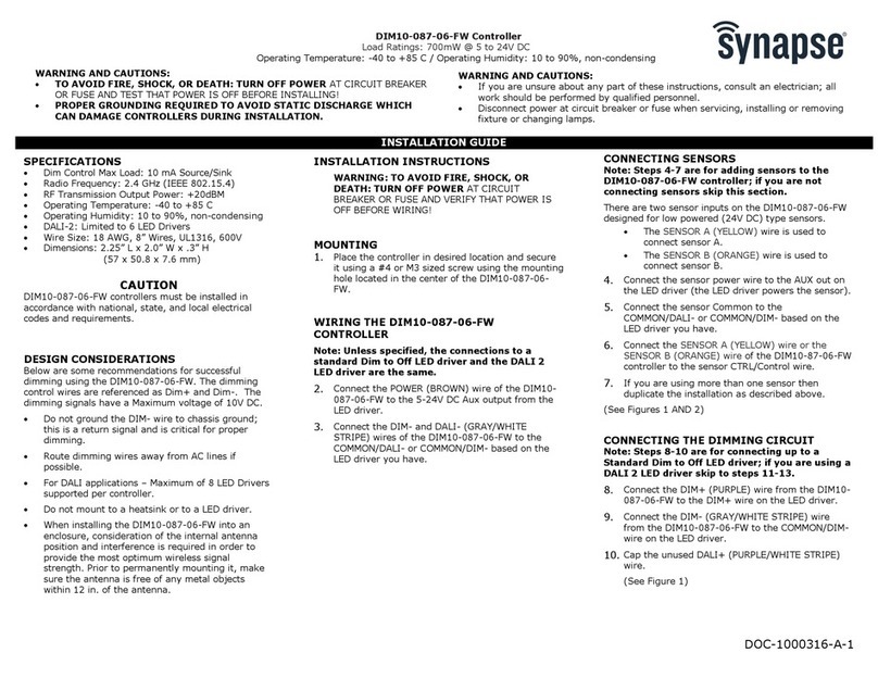
Synapse DIM10-087-06-FW User manual

Synapse

Synapse DIM10-087-06-FW User manual

Synapse DIM10-087-06-F3W User manual

Synapse

Synapse DIM10-087-06-F3W User manual

Synapse DIM10-100-00 User manual

Synapse

Synapse DIM10-100-00 User manual

Synapse DIM10-220 User manual

Synapse

Synapse DIM10-220 User manual

Synapse DIM10-281-21 User manual

Synapse

Synapse DIM10-281-21 User manual

Synapse DIM10-087-06-IP User manual

Synapse

Synapse DIM10-087-06-IP User manual

Synapse DIM10-087-06 User manual

Synapse

Synapse DIM10-087-06 User manual

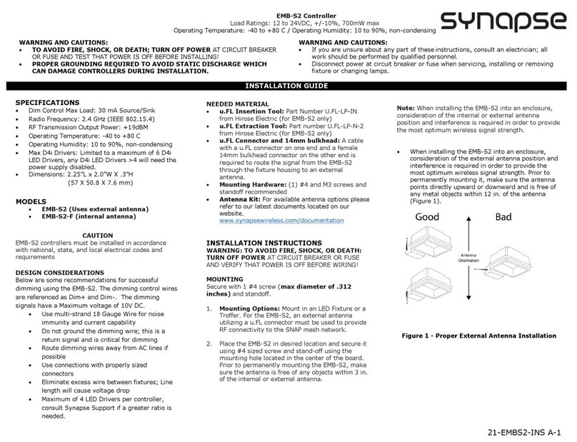
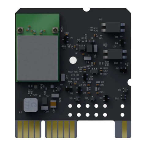
Synapse EMB-S2 User manual

Synapse

Synapse EMB-S2 User manual

Synapse CONTROL-485-101 User manual

Synapse

Synapse CONTROL-485-101 User manual

Synapse DIM10-087-06-FW User manual

Synapse

Synapse DIM10-087-06-FW User manual

Synapse DIM10-087-00 User manual

Synapse

Synapse DIM10-087-00 User manual

Synapse TL7-HVG User manual

Synapse

Synapse TL7-HVG User manual

Synapse SimplySNAP User manual

Synapse

Synapse SimplySNAP User manual

Synapse SimplySNAP SS420 User manual

Synapse

Synapse SimplySNAP SS420 User manual

Synapse DIM10-087-06-A User manual

Synapse

Synapse DIM10-087-06-A User manual

Synapse ZhA-S1 User manual

Synapse

Synapse ZhA-S1 User manual

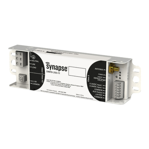
Synapse DIM10-250-11 User manual

Synapse

Synapse DIM10-250-11 User manual

Popular Controllers manuals by other brands

Keba CDF3000 Operation manual

Keba

Keba CDF3000 Operation manual

Marklin Digital 60821 Connection guide

Marklin Digital

Marklin Digital 60821 Connection guide

Allen-Bradley SMC-3 troubleshooting guide

Allen-Bradley

Allen-Bradley SMC-3 troubleshooting guide

Fortinet FortiADC 4000D quick start guide

Fortinet

Fortinet FortiADC 4000D quick start guide

Omron C200H-MC221 - Operation manual

Omron

Omron C200H-MC221 - Operation manual

Tech Controllers EU-F-4z v2 user manual

Tech Controllers

Tech Controllers EU-F-4z v2 user manual

Oase InScenio EGC operating instructions

Oase

Oase InScenio EGC operating instructions

Dynascan FBP206 user manual

Dynascan

Dynascan FBP206 user manual

Johnson Controls VA-77 Series Product bulletin

Johnson Controls

Johnson Controls VA-77 Series Product bulletin

Val Controls IHP24-A Hardware manual

Val Controls

Val Controls IHP24-A Hardware manual

Sentry PRO-TEC Controller Installation, operation & maintenance manual

Sentry

Sentry PRO-TEC Controller Installation, operation & maintenance manual

Grape Solar GS-PWM-10A-IP68 Quick start manual

Grape Solar

Grape Solar GS-PWM-10A-IP68 Quick start manual

DT VIDEOLABS DT18 quick start guide

DT VIDEOLABS

DT VIDEOLABS DT18 quick start guide

Danfoss AK-CC 550A user guide

Danfoss

Danfoss AK-CC 550A user guide

Omron NX701-1 series user manual

Omron

Omron NX701-1 series user manual

BSS Audio Soundweb 9010 installation guide

BSS Audio

BSS Audio Soundweb 9010 installation guide

Tion BS310 user manual

Tion

Tion BS310 user manual

ABB GPS2436 user guide

ABB

ABB GPS2436 user guide

manuals.online logo
manuals.online logoBrands
  • About & Mission
  • Contact us
  • Privacy Policy
  • Terms and Conditions

Copyright 2025 Manuals.Online. All Rights Reserved.