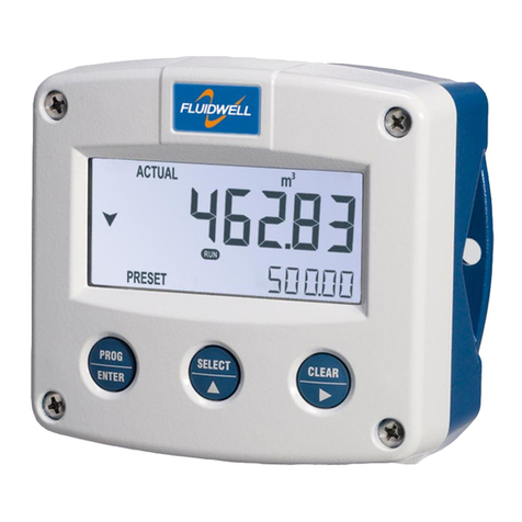
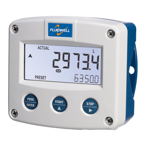
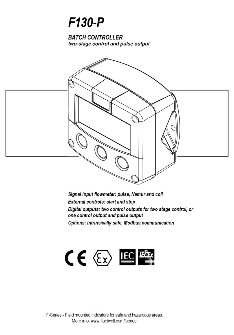
Fluidwell N Series User manual

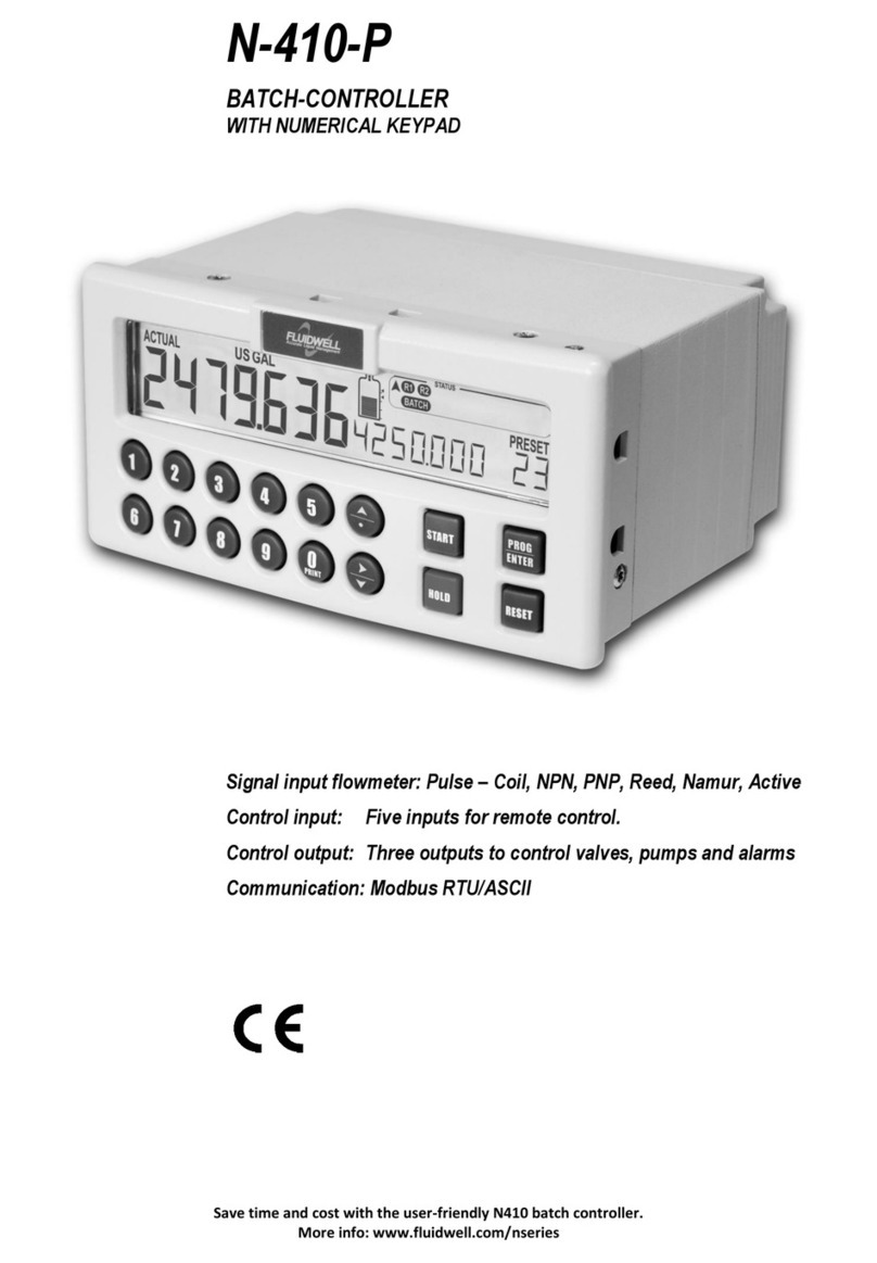
N413-P
BATCH-CONTROLLER
WITH NUMERICAL KEYPAD and RECEIPT PRINTER DRIVER
Signal input flowmeter: Pulse –Coil, NPN, PNP, Reed, Namur, Active
Control input: Five inputs for remote control.
Control output: Five outputs to control valves, pumps and alarms
Communication: Printer interface for receipt printing
Save time and cost with the user-friendly N413 batch controller.
More info: www.fluidwell.com/nseries

FW-N413-P-M_v0204_01_EN.docx
Page 2

FW-N413-P-M_v0204_01_EN.docx
Page 3
DISCLAIMER
•The information contained in this document is subject to change without notice. The
manufacturer makes no representations or warranties with respect to the contents
hereof and specifically disclaim any implied warranties of merchantability or fitness
for a particular purpose.
•If a company or individual makes changes to the N413-P to the extent that the
metrological characteristics are changed, that specific device is no longer traceable
to the NTEP Certificate of Conformance.
SAFETY INSTRUCTIONS
•Electro static discharge does inflict irreparable damage to electronics! Before
installing or opening the unit, the installer must discharge himself by touching a
well-grounded object.
•This unit must be installed in a (control) cabinet.
•This unit must be installed in accordance with the EMC guidelines (Electro Magnetic
Compatibility).
•Grounding: a proper grounding to the aluminum casing must be connected as
directed.
FEDERAL COMMUNICATIONS COMMITTEE (FCC)
This device complies with FCC 47 CFR 15. Operation is subject to the following two
conditions:
(1) This device may not cause harmful interference.
(2) This device must accept any interference received, including interference that may
cause undesired operation.
DISPOSAL - WEEE DIRECTIVE
•The WEEE Directive requires the recycling of disposed electrical and electronic
equipment in the European Union.
•Whilst the WEEE Directive may not apply to your region, we support its policy and
ask you to be aware on how to dispose of this product.
•The crossed out wheelie bin symbol illustrated and found on our products signifies
that this product should not be disposed of in general waste or landfill.
•Please contact your local dealer, national distributor or the manufacturer’s
Technical Services for information on product disposal.
SAFETY RULES AND PRECAUTIONARY MEASURES
▪The manufacturer accepts no responsibility whatsoever if the following safety rules, precautions,
instructions and the procedures as described in this manual are not followed.
▪Modifications of the N413-P implemented without preceding written consent from the
manufacturer, will result in the immediate termination of product liability and warranty period.
▪Installation, use, maintenance and servicing of this equipment must be carried out by authorized
technicians.
▪Check the mains voltage and information on the manufacturer's plate before installing the unit.
▪Check all connections, settings and technical specifications of the various peripheral devices
with the N413-P supplied.
▪Open the casing only if all leads are free of potential.
▪Never touch the electronic components (ESD sensitivity).
▪Never expose the system to heavier conditions than allowed according to the casing
classification (see manufacture's plate).
▪If the operator detects errors or dangers, or disagrees with the safety precautions taken, then
inform the owner or principal responsible.
▪The local labor and safety laws and regulations must be adhered to.

FW-N413-P-M_v0204_01_EN.docx
Page 4
INTENDED USE
The N-SERIES is intended for use in safe areas (ordinary locations). The N-SERIES is designed
and constructed for measurement purposes in industrial processes to show the flowrate, the total
and the accumulated total of a medium that passes a sensor. For details, refer to the chapter:
Technical specifications.
Mechanical work
Only qualified and well-trained persons who are familiar with the mechanical installation and the
service procedures and who obey the specific regulations and the requirements set by the
authorities, the manufacturer, the employer and the plant owner, are allowed to do the mechanical
work.
Electrical work
Only qualified and well-trained persons who are familiar with the electrical installation and the
service procedures and who obey the specific regulations and requirements set by the authorities,
the manufacturer, the employer and the plant owner, are allowed to do the electrical work.
UNINTENDED USE
A hazardous situation may occur if the N-SERIES is not used for the purpose it was designed
for or is used incorrectly. Please obey the information as given in this instruction manual:
▪Do not use the N-SERIES in a hazardous area.
▪Do not use the N-SERIES in life support applications. A possible malfunction of the N-SERIES
can cause (serious) injury or death to persons.
TARGET GROUP
This publication is aimed at the persons who are:
▪involved in the preparation of the required work;
▪involved in the installation, commissioning work and use of the N-SERIES;
▪appointed to supervise the required work;
▪appointed for the certification, the occupational, health, safety and the quality tasks.
WARRANTY AND TECHNICAL SUPPORT
For warranty and technical support for your Fluidwell products,
visit our internet site www.fluidwell.com or contact us at support@fluidwell.com.

FW-N413-P-M_v0204_01_EN.docx
Page 5
ABOUT THE OPERATION MANUAL
This operation manual is divided into two main sections:
▪The daily use of the unit is described in chapter 2 "Operation". These instructions are meant for
users.
▪The following chapters and appendices are exclusively meant for electricians/technicians. These
provide a detailed description of all software settings and hardware installation guidance.
This operation manual describes the standard unit as well as most of the options available. For
additional information, please contact your supplier.
A hazardous situation may occur if the N413-P is not used for the purpose it was designed
for or is used incorrectly. Please carefully note the information in this operating manual
indicated by the pictograms:
A "warning" indicates actions or procedures which, if not performed correctly, may lead to
personal injury, a safety hazard or damage of the N413-P or connected instruments.
A "caution" indicates actions or procedures which, if not performed correctly, may lead to
personal injury or incorrect functioning of the N413-P or connected instruments.
A "note" indicates actions or procedures which, if not performed correctly, may indirectly
affect operation or may lead to an instrument response which is not planned.
Firmware version: 03.06.xx
Manual: FW-N413-P-M_v0204_01_EN.docx
© Copyright 2018: Fluidwell B.V. - The Netherlands.
Information in this manual is subject to change without prior notice. The
manufacturer is not responsible for mistakes in this material or for incidental
damage caused as a direct or indirect result of the delivery, performance or
use of this material.
© All rights reserved. No parts of this publication may be reproduced or used
in any form or by any means without the written permission of your supplier.

FW-N413-P-M_v0204_01_EN.docx
Page 6
CONTENTS MANUAL
Disclaimer................................................................................................................................... 3
Safety instructions...................................................................................................................... 3
Federal Communications Committee (FCC).............................................................................. 3
Disposal - WEEE Directive......................................................................................................... 3
Safety rules and precautionary measures.................................................................................. 3
Intended use............................................................................................................................... 4
UnIntended use.......................................................................................................................... 4
Target group............................................................................................................................... 4
Warranty and technical support.................................................................................................. 4
About the operation manual....................................................................................................... 5
Contents manual ........................................................................................................................ 6
1. Introduction......................................................................................................................... 7
1.1. System description of the N413-P.............................................................................................7
2. Operational ....................................................................................................................... 10
2.1. General...................................................................................................................................10
2.2. Control panel...........................................................................................................................10
2.3. Operator information and functions.........................................................................................11
2.4 Operator Alarms......................................................................................................................13
3. Installation......................................................................................................................... 14
3.1. General directions...................................................................................................................14
3.1.1. General installation overview..................................................................................................14
3.2. Mechnical installation..............................................................................................................14
3.2.1. Dimensions enclosure.............................................................................................................14
3.2.2. Installation / surrounding conditions........................................................................................15
3.2.3. Preparation .............................................................................................................................15
3.2.4. Install the unit into the cabinet (panel).....................................................................................16
3.3 Electrical installation................................................................................................................16
3.3.1. Introduction .............................................................................................................................16
3.3.2. Voltage selection sensor supply..............................................................................................16
3.3.3. Terminal connectors................................................................................................................17
4. Configuration .................................................................................................................... 23
4.1. Introduction.............................................................................................................................23
4.2. Programming SETUP-level.....................................................................................................23
4.2.1. General...................................................................................................................................23
4.2.2. Overview functions SETUP level.............................................................................................25
4.2.3. Explanation OF SETUP 1 - Preset..........................................................................................26
4.2.4. Explanation OF SETUP 2 - Overrun .......................................................................................26
4.2.5. Explanation OF SETUP 3 - Flowrate.......................................................................................27
4.2.6. Explanation OF SETUP 4 - Alarm...........................................................................................27
4.2.7. Explanation OF SETUP 5 - Display.........................................................................................27
4.2.8. Explanation OF SETUP 6 - Flowmeter....................................................................................28
4.2.9. Explanation OF SETUP 7 - Control.........................................................................................29
4.2.10. Explanation OF SETUP 8 - Printer..........................................................................................30
4.2.11. Explanation OF SETUP 9 - Others..........................................................................................31
5. Maintenance ..................................................................................................................... 32
5.1. General directions...................................................................................................................32
5.2. Repair .....................................................................................................................................32
5.3. Repair policy ...........................................................................................................................32
Appendix A: Technical specification.........................................................................................33
Appendix B: Problem solving ...................................................................................................35
Appendix C: Declaration of conformity.....................................................................................36
Index of this manual ................................................................................................................. 37
List of figures in this manual..................................................................................................... 37

FW-N413-P-M_v0204_01_EN.docx
Page 7
1. INTRODUCTION
1.1. SYSTEM DESCRIPTION OF THE N413-P
Functions and features
The batch controller model N413-P is a microprocessor driven instrument designed for batching and
filling of small and large batch size quantities.
This product has been designed with a focus on:
▪Ease of use with the numerical keypad,
▪Ruggedness for its application with a robust enclosure, keypad and mechanical relays,
▪Clear operator information: all relevant data can be monitored at a glance,
▪User friendly installation with standard high quality plug and play terminals and suitable for both
AC and DC applications.
▪Wide range of inputs, outputs and functions for any application.
Figure 1: Typical application for the N413-P
Flowmeter input
▪One flowmeter: a passive or active pulse, Namur or coil signal output can be connected to the
N413-P. The input circuit supports low and high frequency flowmeters. A proper sensor supply is
available to power the sensor with 8 / 12 or 24V DC.
Control inputs
▪Five control inputs: the functions available are START, HOLD, RESET, keyboard lock and
External alarm.
Receipt printer interface
A printer interface to allow printing of receipts that go along with completed batches.

FW-N413-P-M_v0204_01_EN.docx
Page 8
Control outputs
▪Two mechanic relay outputs are mainly used for one or two-stage batch control processes.
The function of the relay R1 (SPDT) is fixed and is set for batch control (Batch). In most
applications, this relay is used as the main batch control relay.
The function of the relay R2 (SPDT) is configurable in the setup menu and can be set as batch
relay (Batch) or as an output for two-stage control (Preclose), or as an alarm output (Alarm), or
as a scaled pulse output (Pulse) or to switch a pump (on/off).
▪Three transistor outputs: mainly used for connection to PLC’s or other controlling equipment.
The function of the transistor configurable in the setup menu and can be set as batch relay
(Batch) or as an output for two-stage control (Preclose), or as an alarm output (Alarm), or as a
scaled pulse output (Pulse) or to switch a pump (on/off).
Receipt information
After each completed batch a receipt is printed on an external device. Additional receipts can
be printed on demand.
Below example shows a printed receipt. The arrows indicate the items that can be configured.
For configuration details and options see chapter 4.
====================
FLUIDWELL F132P
--------------------
Date: 01/01/10
Time: 12:34:56
Unit ID: 0
Deliv. No: 7
Deliv. total:
546 L
Accum. total:
2865668 L
====================
Figure 2: Typical layout of a printed receipt
Power supply
The N413-P will operate on an AC or a DC power supply:
▪110-230V AC;
▪24V DC.
Configuration of the unit
The N413-P was designed to be implemented in many types of applications. For that reason a
SETUP menu is available to configure your N413-P according to your specific requirements.
SETUP includes several important features, such as K-factors, measuring units, selection of the
control outputs, receipt information, etc.
Power failure
Information will not be lost in the event of power failure:
•all settings are stored in EEPROM memory.
•a just-in-time backup is built in to write the latest batch information and (accumulated) total into
the memory.
4 configurable headers
Timestamp upon
batch delivery
Tagnumber of unit
Delivered total
Number of
completed batches
Adjustable
number of
blank rows
Accumulated total

FW-N413-P-M_v0204_01_EN.docx
Page 9
Display information
The unit has a large LCD with a bright LED backlight and displays all kinds of symbols, digits and
measuring units, status information and key-word messages.
1. Numeric keys
2. Rate key
3. Total key
4. Count key
5. Function select/digit delete key
6. Function select/period set key
7. Interrupt key
8. Start/Resume key
9. Reset key/ID Number
10. Program/confirm key
11. 8 mm value display
12. Status indicators
13. Overrun/Preopen busy
indicator*
14. Key lock indicator
15. Relay2 indicator
16. Relay1 indicator
17. Increase/decrease indicator
18. Tank fill/spill indicator
19. Unit indicator
20. 14mm value display
P Print key
* Preopen busy: Batch indicator and clock blinks. Overrun busy: Ready indicator and clock blinks
Figure 3: Display and control panel
1 Model number and name
2 Safety information
3 General safety information
4 Sensor supply data
5 Additional information
6 Serial number
7 Manufacturer data
Figure 4: Typical identification label
12345
67 8 9 0
R A T E T O T A L C O U N T P R IN T
S T A R T
H O L D R E S E T
P R O G
E N T E R
1
2345 6 78 9
10
11
12
13
14
1516
17
1819
20
1212
P

FW-N413-P-M_v0204_01_EN.docx
Page 10
2. OPERATIONAL
2.1. GENERAL
▪The N413-P may only be operated by authorized and trained personnel.
▪All instructions in this manual are to be observed.
▪Take careful notice of the "Safety rules, instructions and precautionary measures" in
the front of this manual.
This chapter describes the daily use of the N413-P. This instruction is meant for users / operators.
2.2. CONTROL PANEL
The following keys are available:
Figure 5: control panel
Functions of the keys
Once PROG has been pressed, the keys 0to 9and ●are used to enter a PRESET value
or configuration value.
During editing of the receipt header, this key is used to increase the value of the selected
digit.
RATE: to display the actual flowrate during batching.
TOTAL: to display and reset the actual Total and after pressing twice to display the
accumulated total.
COUNT: to display and reset the number of fully executed batches.
ID Number (only available if enabled): to enter or display a unique number (e.g. batch,
customer or driver number) that will be printed on the ticket.
PRINT: to print a receipt.
During editing of the receipt header, this key is used to move the cursor to the left.
Once PROG has been pressed: to enter a decimal value. During configuration,
this key is used to select a function or value; please read chapter 4. During editing of the
receipt header, this key is used to increase the value of the selected digit.
During configuration, this key is used to select a function or value; please read chapter 4.
During editing of the receipt header, this key is used to move the cursor to the left.
To START the batch process or to resume after a HOLD command.
To HOLD (interrupt) the batch process.
To program and save a new PRESET value or other settings. It is also used to gain
access to SETUP-level; please read chapter 4.
Once HOLD has been pressed, the batch process is terminated after pressing RESET.
Reset is also used to accept alarms. During editing of the receipt header, this key is used
to abort the edit session, the previous values are restored (press momentarily) or to erase
the full header line (press long).
RATE TOTAL COUNT PRINT
START
HOLD
PROG
RESET
ENTER
FW-4100-000002-001-EN
FW-4100-000013-001-EN
FW-4100-000015-001-EN
FW-4100-000003-001-EN
RATE
TOTAL
FW-4100-000004-001-EN
COUNT
FW-4100-000005-001-EN
PRINT
FW-4100-000006-001-EN
FW-4100-000007-001-EN
FW-4100-000008-001-EN
START
FW-4100-000009-001-EN
HOLD
FW-4100-000010-001-EN
PROG
ENTER
FW-4100-000011-001-EN
RESET
FW-4100-000012-001-EN

FW-N413-P-M_v0204_01_EN.docx
Page 11
2.3. OPERATOR INFORMATION AND FUNCTIONS
In general, the N413-P will always function at Operator level. The information displayed and the
functional keys available are dependent upon the SETUP-settings and the active function.
NOTE:
If the key-sign is displayed,
the particular key(s) or functions are not accessible!
▪To enter a batch quantity
To change the PRESET-value, following procedure must be followed:
1) Press PROG: the word "PROGRAM" will be flashing,
2) Use the numerical keypad 0-9 and decimal position (set with SETUP 1.2 of the
configuration menu) to enter the desired value.
3) Set the new PRESET-value by pressing ENTER.
Figure 6: Example display information during programming preset value.
When data is altered but ENTER has not been pressed, and then the alteration can still be
cancelled by pressing RESET: the former value will be reinstated. The PRESET-value can be
used time after time until a new value is programmed.
Please note that alterations will only be set after ENTER has been pressed!
▪Batch maximum / minimum
When you program a new value which is not valid - the batch size is too large or too small -
the increase or decrease-sign(e.g.) will be displayed while you are programming; the new
value will not be accepted but the minimum or maximum allowed value will be set.
▪Tank fill symbol
The batch process can be visualized with the tank fill symbol. This graphical
representation can be enabled or disabled.
When the batch overfills the preset quantity by 2.5% the graph will show two overspill
arrows indicating this condition.
▪Starting up the batch process
The batch process can only be started up when "READY" is displayed. The batch process is
started by pressing the START-key. Depending on the SETUP-settings, one or two relays will
be switched. The arrows at the display indicate if the ACTUAL-value will be counting up or
down.
Once the PRESET quantity is reached, the batch outputs will be switched off and the batch
process is ended. A next batch can be started with the same PRESET quantity or a new value
can be entered.
If the PRINT command is set to ON-CONFirmation, it is not possible to start a new batch until
the receipt of the current batch is printed or cancelled for printing.
The N413-P is equipped with a smart –self learning –overrun correction: at the end of the
process, the outputs will be switched-off earlier as the PRESET value, taking the overrun
quantity of previous batches into account. The result is an accurate batch, even in slowly
varying circumstances. During overrun, a clock will be displayed and R1 / R2 will be flashing.
Figure 7: Example display information during the process.
FW-4100-000014-001-EN

FW-N413-P-M_v0204_01_EN.docx
Page 12
ID Number
(Only available if enabled). It might be that an ID number (e.g. customer, driver, tank, …) will
be asked before a batch can be started. This numeric value can be entered immediately. By
pressing the START-key (or by activating external control ‘START’), the entered value will be
accepted and the batch started immediately. The entered ID value will be printed on the ticket.
If an ID value is presented already (e.g. driver ID), START can be pressed immediately
without changing the value (this is for repeating applications where the same ID can be
reused).
By pressing HOLD or RESET, this process can be stopped while returning to READY-state.
When ID-INPUT mode is set to HAND or REPEAT, the operator has the possibility to change
the ID-value when the displays shows READY.
▪To enter a new ID-value
To change the ID-value, following procedure must be followed:
1) Show the ID by pressing the 9-key
2) Press PROG: the word "PROGRAM" will be flashing
3) Use the numerical keypad 0-9 to enter the desired value
4) Set the new ID-value by pressing ENTER.
5) Return to the main screen by pressing the 9-key again.
▪Interrupting and ending the batch process
1. Press HOLD: Interrupts the batch process temporarily, the pump stays on and the actual
data is kept while the display shows HOLD (flashing).
2. Press HOLD, START, The interrupted batch is resumed.
OR:
Press HOLD, RESET: Stops the batch process at any time, the batch sequence is ended as
a completed batch and the remaining quantity of the batch is ignored. It is possible to print a
ticket as with a normal ended batch. Note that you cannot resume the batch.
3. When the batch is stopped and the display shows READY, press RESET for 3 seconds: The
actual batch data is erased and cannot be printed anymore.
You can start a new batch when the display shows 0.
Figure 8: Example display information when interrupted.
▪Power failure during a batch process
When during a batch a power failure occurs, the latest batch information is saved and made
available again at power-up. It is not possible to resume the batch. The information is only
available to print a receipt. After the power failure, the display will show “powerfail”. Before a
new batch is possible, the user must confirm the power failure by pressing the reset-key.
The following information is available on request:
▪Flowrate indication
During batching, the actual flowrate will be displayed after pressing the RATE-key. To return
to the main display: press RATE again or wait for 20 seconds.
▪Display total and accumulated total
When the TOTAL-key is pressed once, the resettable total will be displayed. After pressing
this key again, the accumulated total will be displayed.
The accumulated total cannot be reset. The value will count up to 9,999,999,999. The
measurement unit and the number of decimals are displayed according to the configuration
settings for preset. To return to the main display: press TOTAL again or wait for 20 seconds.

FW-N413-P-M_v0204_01_EN.docx
Page 13
▪Clear total
Total can only be reset if no batch process is active (status: READY).
This function might not be available due to configuration settings.
The value for total can be re-initialized. To do so, select Total and press RESET:
the flashing text "PUSH RESET" will be displayed.
To avoid a reset at this stage, press another key than RESET or
wait for 20 seconds. If RESET is pressed again, TOTAL will be reset to zero.
The reset of total DOES NOT influence the accumulated total.
▪Display batch counter
The number of completed batches is displayed after pressing COUNT. To return to the main
display: press COUNT again or wait for 20 seconds.
▪Print a receipt ticket
Depending on the configuration settings, at the end of a completed or stopped batch:
a) The N413-P prints a ticket automatically (AUTO).
b) The N413-P shows the RECEIPT PUSH PRINT message. When you push the PRINT key,
the ticket is printed (on confirmation). When you press momentarily any numerical key or
the RESET key, the print command is ignored and the N413-P becomes ready for the next
batch.
c) The N413-P acts as a batch controller without a printer function. If you want to print a
ticket, just press the PRINT key (on demand, by hand).
▪ID Number
(only available if enabled). By pressing “9”, the actual ID that will be printed on the ticket will
be displayed. If enabled, the value can be modified after pressing the PROG-key.
2.4 OPERATOR ALARMS
▪General alarm
When “ALARM” is displayed when no process alarm is present (e.g. no flow, press the “1”
key to display the reason of the alarm. Please consult Appendix B: Problem Solving.
▪No flow alarm
The N413-P offers a no-flow monitoring feature: if the flowmeter fails to generate a signal
during a certain period of time, the unit will shut-off the control output(s) and bring the batch
controller in HOLD and alarm mode: an alarm message will be displayed, indicating the type
of alarm: “NO FLOW”.
To clear the alarm press RESET once, while the batch controller remains in HOLD mode.
When in HOLD mode, the batch can be continued or terminated. (See “Interrupting and
ending the batch process”)
▪External alarm
The N413-P can receive an external alarm during a batch. This can be set with SETUP 7.1 –
Alarm. When the alarm is activated a running batch will be interrupted immediately and any
other function will be blocked until the alarm status is cleared.
The display will show ‘EXT ALARM’.
To clear the alarm press RESET once, while the batch controller remains in HOLD mode.
When in HOLD mode, the batch can be continued or terminated. (See “Interrupting and
ending the batch process”)

FW-N413-P-M_v0204_01_EN.docx
Page 14
3. INSTALLATION
3.1. GENERAL DIRECTIONS
•Installation, electrical wiring, start-up and maintenance of this instrument may only be
carried out by authorized and trained personnel. Personnel must read and understand
this Instruction Manual before carrying out any work.
•The N413-P may only be operated by personnel who are authorized and trained by the
operator of the facility. All instructions in this manual are to be observed.
•Make sure, the measuring system is correctly wired up according to the wiring
diagrams. Protection against accidental contact is no longer assured when the
housing cover is removed or the panel cabinet has been opened (danger from
electrical shock). The housing may only be opened by authorized personnel.
•Take careful notice of the "Safety rules, instructions and precautionary measures" in
the front of this manual.
•Electro static discharge may inflict irreparable damage to electronics! Before
installing or opening the unit, the installer must be discharged by touching a well-
grounded object.
•This unit must be installed in accordance with the related certificates, the plant
owner’s and the manufacturer’s instructions and the prevailing (inter)national
Standards and Regulations.
•Both internal power supply as well as the relays are double insulated.
•To improve ESD sensitivity it is recommended to ground the conductive front panel at
one of the chassis ground points.
•Grounding: Do ground (PE) the aluminum enclosure part properly as indicated. Two
grounding positions are available: one on the top side (photo) and one on the bottom
side. Use the supplied M4 x 6mm thread forming screw with a lock washer.
3.1.1. GENERAL INSTALLATION OVERVIEW
This overview gives an outline of the installation procedure for a general installation (not compliant
for custody transfer. For detailed instructions, refer to the next paragraphs.
1. Prepare the installation area for installation of the N413-P.
2. Unpack and prepare the N413-P for installation.
3. Install the N413-P mechanically.
4. Install the N413-P electrically.
5. Program the N413-P as required, refer to chapter 4; Configuration.
6. For future reference, fill in the list of settings (in the back of this manual).
7. Commission the N413-P.
8. When the N413-P is successfully commissioned, put the N413-P into service.
3.2. MECHNICAL INSTALLATION
3.2.1. DIMENSIONS ENCLOSURE
Figure 9: Dimensions enclosure (Connector layout is a typical configuration).

FW-N413-P-M_v0204_01_EN.docx
Page 15
3.2.2. INSTALLATION / SURROUNDING CONDITIONS
Take the relevant IP classification of the enclosure into account (see manufactures plate). Even with
an IP67 (Type 4X) enclosure, the unit should not be exposed to harsh unnecessary harsh weather
conditions. When used in extreme cold surroundings or varying climatic conditions, take the
necessary precautions against moisture by placing a dry sachet of silica gel, for example, inside the
control cabinet.
Mount the N413-P on a solid structure to avoid vibrations. The following environmental conditions
apply:
Relative humidity: < 85% RH.
Outdoor use: not suitable for outdoor use.
IP and NEMA rating: IP67 and NEMA Type 4X (front only), IP20 rear.
Supply voltage fluctuation: +/- 10% unless stated otherwise.
Means of protection: Class II (isolated).
Over-voltage category: II.
Pollution degree: 2 (internal environment), 3 (external environment).
Ambient: -20 °C to +60 °C, -4 °F to + 140 °F.
Altitude: up to 2000 m.
3.2.3. PREPARATION
1. Make sure, the unit and the
related installation parts are
complete, not damaged or
tampered with.
2. Determine the location for the
installation of the unit. Mind
the physical and ergonomic
limitations by the cabinet, the
line-of-sight and the
installation area.
3. Make the required hole(s) in
the panel.
4. Deburr the hole(s) and clean
the work area.
Figure 10: Cut out cabinet.

FW-N413-P-M_v0204_01_EN.docx
Page 16
3.2.4. INSTALL THE UNIT INTO THE CABINET (PANEL)
1. Install the screws in the clamps (1, 3, 4, 7).
2. Install the gasket onto the unit (2).
3. Put the unit (2) in the correct position for
installation.
4. Install the top clamp (1) and tighten the
screws by hand.
5. Install the other clamps (4, 3, 7) and tighten
the screws by hand.
6. Make sure, the unit (2) is installed in the
correct position.
7. Torque-tighten, with 0.6 Nm ± 0.1 Nm, the
screws top-bottom-left-right.
8. For later installation, keep the security cap
for the W&M switch at the unit (2).
For clarity, some parts are not shown or numbered.
3.3 ELECTRICAL INSTALLATION
3.3.1. INTRODUCTION
•Make sure, the installation is made safe and the activities are approved by the
responsible person. Lock-out/Tag-out the related systems as applicable before you
start the work.
•Electro static discharge may inflict irreparable damage to electronics! Before
installing or opening the unit, the installer must be discharged by touching a well-
grounded object.
•This unit must be installed in accordance with the related certificates, the plant
owner’s and the manufacturer’s instructions and the prevailing (inter)national
Standards and Regulations.
•Both internal power supply as well as the relays are double insulated.
•To improve ESD sensitivity it is recommended to ground the conductive front panel at
one of the chassis ground points.
•Grounding: Do ground the aluminum enclosure part properly as indicated. Two
grounding positions are available: one on the top side (photo) and one on the bottom
side. Use the supplied M4 x 6mm thread forming screw with a lock washer.
On the top of the N413-P
At the bottom of the N413-P
Figure 11: Grounding enclosure (Protective Earth PE).
3.3.2. VOLTAGE SELECTION SENSOR SUPPLY
Sensor supply: 8.2V - 12V or 24 V DC:
A real power supply for the sensor is available.
The flowmeter can be powered with 8.2, 12 or
24V DC. Total power consumption: max.
50mA@24V. The voltage is selected with the
two switches at the left rear of the enclosure.
Refer to the figure 15 to select the required
sensor supply voltage.
Figure 12: Switch setting sensor supply voltage.

FW-N413-P-M_v0204_01_EN.docx
Page 17
Cable and wire selection
The unit complies with the Directives and Standards for Electro Magnetic Interference. For a reliable
signal transfer and prevention of external signal interference (crosstalk), for signal wiring, the
recommendation is made for a shielded (twisted pair) cable which meets at least the Category 5
cable standard.
3.3.3. TERMINAL CONNECTORS
The following terminal connectors are available:
Figure 13: Overview of terminal connectors N413-P.
Terminal 1 - 2; Lock keypad:
This function allows you to connect a lock or jumper in order to completely disable the keypad while
the functions from the terminals remain available. Note that certain keys on the keypad can be
locked-out with SETUP 9.5 or password protected: read par. 4.2.11.
Read “Terminal 8-11” to lock the batch process.
Terminal 3 to 5, 29 to 32; Flowmeter inputs and supply:
Three basic types of flowmeter signals can be connected to the unit: pulse, active pulse or coil. The
screen of the signal wire must be connected to the common ground terminal.
The input signal type has to be selected with the correct SETUP-function (read par. 4.2.8.).

FW-N413-P-M_v0204_01_EN.docx
Page 18
Sine-wave signal (Coil):
The N413-P can be connected to flowmeters that have a coil output signal. With SETUP 6.1 two
sensitivity levels can be selected:
•COIL LO: sensitivity from about 120mVp-p.
•COIL HI: sensitivity from about 20mVp-p
Figure 14: Terminal connections - Coil signal input (typical)
Reed-switch:
The N413-P is suitable for use with flowmeters which have a reed-switch. To avoid pulse bounce
from the reed-switch, it is advised to select REED LP - low-pass filter (read par. 4.2.8.)
Figure 15: Terminal connections - Reed-switch signal input (typical)
Namur:
The N413-P is suitable for flowmeters with an Namur signal. The N413-P is able to power the Namur
sensor, as an external power supply for the sensor is not required.
Figure 16: Terminal connections - NAMUR signal input (typical)

FW-N413-P-M_v0204_01_EN.docx
Page 19
Pulse-signal NPN / NPN LP:
The N413-P is suitable for use with sensors which have a NPN output signal. For reliable pulse
detection, the pulse amplitude has to go above 1.2V. Signal setting NPN-LP employs a low-pass
signal noise filter, which limits the maximum input frequency - read par. 4.2.8.
Figure 17: Terminal connections - NPN signal input (typical)
Active signal:
If a sensor gives an active signal (read chapter 3). The detection levels are 50% of the selected
supply voltage; approx. 4V (8-1 DC) or 6V (12 DC) or 12V (24 DC).
Figure 18: Terminal connections - Active signal input (typical)
Pulse-signal PNP / PNP LP:
The N413-P is suitable for use with sensors which have a PNP output signal. For reliable pulse
detection, the pulse amplitude has to go above 1.2V. Signal setting PNP-LP employs a low-pass
signal noise filter, which limits the maximum input frequency - read par. 4.2.8.
A sensor supply voltage of 8.2, 12 or 24V DC can be provided by terminal 29.
Figure 19: Terminal connections - PNP signal input (typical)

FW-N413-P-M_v0204_01_EN.docx
Page 20
Terminal 8 - 9; External control - Start
With this function, the batch controller can be STARTED remotely. The input must be switched with
a potential free contact to the GND-terminal number 8 for at least 100msec.
Note: in case the function “ID” is enabled (setup 5.5), external start must be switched twice to start a
batch!
Figure 20: Terminal connections - External start (typical)
Terminal 8-10; External control - Hold
With this function, the batch process can be interrupted and brought to HOLD status. The input must
be switched with a potential free contact to the GND-terminal number 8 for at least 100msec.
Figure 21: Terminal connections - External hold (typical)
Terminal 8-11; External control - Reset Batch
With this function, the batch process in HOLD status can be cleared remotely with this RESET
function. The input must be switched with a potential free contact to the GND-terminal number 8 for
at least 100msec.
Terminal 11 can also be used to block the batch process: as long as this input is switched to
Terminal 8, it is not possible to start a batch (the START button on the keyboard is blocked as well).
Figure 22: Terminal connections - External reset (typical)
This manual suits for next models
1
Table of contents
Other Fluidwell Controllers manuals

Fluidwell
Fluidwell F Series User manual

Fluidwell
Fluidwell F130-P User manual

Fluidwell
Fluidwell F131-P User manual

Fluidwell
Fluidwell F131-P User manual

Fluidwell
Fluidwell N-410-P User manual

Fluidwell
Fluidwell F030-A User manual

Fluidwell
Fluidwell F133-P User manual

Fluidwell
Fluidwell F133-P User manual

Fluidwell
Fluidwell D030-P Series User manual

Fluidwell
Fluidwell F130-P User manual