Tradingate TILT User manual

TILT
ORIGINAL OPERATING INSTRUCTIONS
DEAR CUSTOMER,
Thank you for purchasing this product. Pl as r ad all th instructions in this manual
car fully, b for you ass mbl or us th product. Should you pass on this product to third
parti s, pl as hand ov r th instruction manual along with it.

1. IMPORTANT SAFETY INFORMATION
Make sure the power supply (AC110V or AC220V) of the gate operator is
suitable for the power supply of the electrical outlet you are using.
Do not allow chil ren to play with fixe controls. Keep remote controls away from
chil ren.
Remote control is single button control; it means that one button control ON,
STOP, OFF mol , when press button for each mol , the in icator lighte . In
a tion to the remote control operating mol , manually free the key can be use to
liberating the motor an oor, the oor can be runne manually, pull own the
relief han le 90 egrees into horizontal position for relief, relief the han le an
close for locking. See the instructions 9.
When operating a biase -off switch, make sure that other persons are kept away.
Frequently examine the installation for imbalance an signs of wear or amage to
cables, springs an mounting. Do not use if repair or a justment is necessary.
This equipment is not suit for persons with re uce physical or sensory, mental
capabilities, lack of experience or knowle ge (inclu ing chil ren). Unless they
have been given supervision by a professional person.
Repairs may only be carrie out by professionals with the appropriate knowle ge
about the evice.

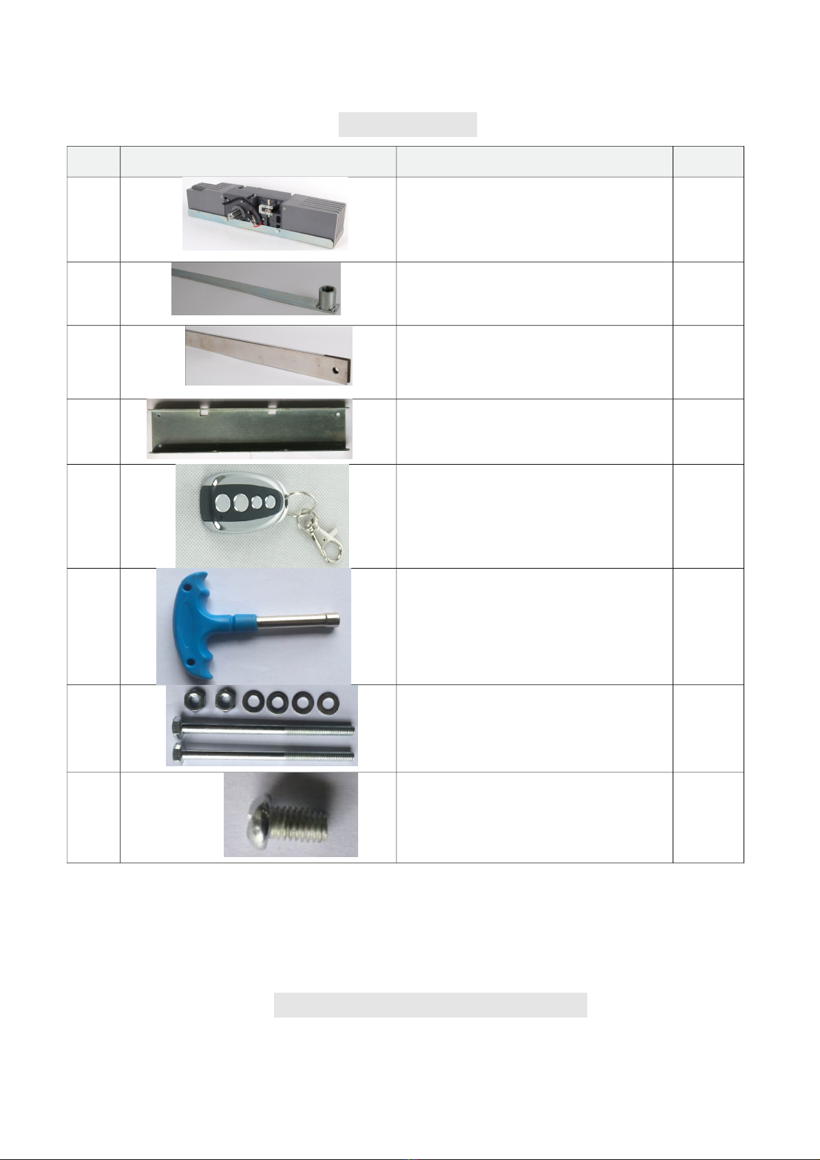
2. PART LIST
3. TECHNICAL INFORMATION
No. Image Description Qty.
1 Gate Operator 1x
2
Ro 1x
3 Sli ing ro 1x
Mounting base plate 1x
4 Remote Control 2x
5 Key (for Manual Operation) 1x
6 Nut (M8) for Gate Operator 2x
7 Retainer bolt M6X10 1x

Type TILT
Power supply 230V 50Hz
Rated output power of motor 200W
Output torque 350N·m
Speed 1.75rpm
Door max. surface 9㎡
Remote control operating distance 30m (Frequency:433.92mHz)
Remote control mode Single button
Limit switch Spring limit switch
Noise ≤58dB
Duty cycle S2 15 minutes
Extra remote control 20
Environmental temperature -20°C ~ +70°C
4. INSTALLATION
4.1 Installation diagram
1 Door

2 Rod & sliding rod
3 TILT motor
4 Remote control
5 Wireless keypad (optional)
Alarm lamp (optional)
4.2 Dimension
4.3 Installation
A、Overall flip up type

B、Overall slide down type
C、Folding type

4.4、Installation of link
A、Unilateral single rod type
B、Unilateral double rods type

C、Intermediate double rod type

D、Installation of two motors
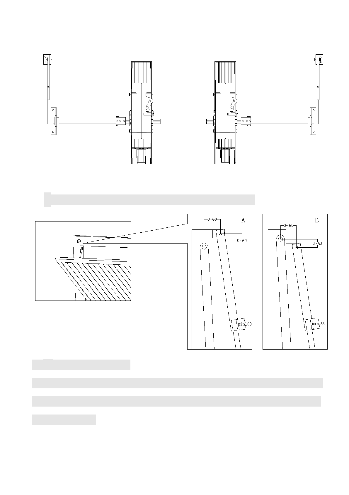
* The relative mounting size of the rod and link
4.5、Manual operation
In case of power failure fit the supplied key in the unlock rod (as
shown below) turn it clockwise 180° then can open or close the
gate manually.


5. WIRE CONNECTION
Fig.1
5.1 Wiring notes of control board
a. Power Input (terminal J3): PE (Earth),L (Live),N (Neutral).
b. Caution light: connect caution light wire to L an N of LAMP(terminal J4)
c. Limit switch: Open limit(13 of J5) ,Com(12 of J5) ,Close limit(11 of J5)

d. Three-button mo e external button switch:Open(2 of J2),Close(1 of J2),Stop
(3 of J2),Com(4 of J2)
e. Single-button mo e external button switch: Single-button(5 of J2),Com(4 of J2)
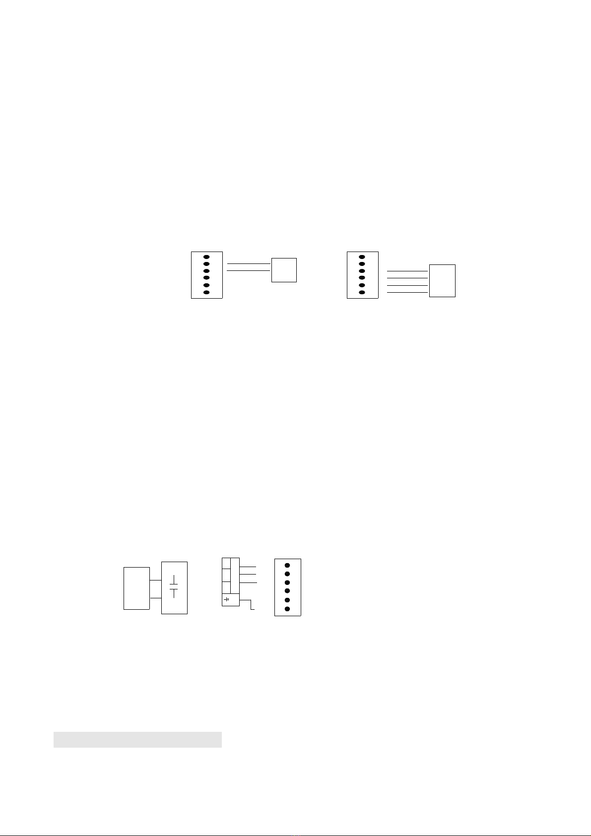
f.Output power supply: 12VDC(7 of J5), COM (9 of J5), I.R. (8 of J5 is N.C
Infrare )
If the infrare beam is interrupte uring closing, the gate will reverse an open
imme iately. The pro uct is not factory equippe with an infrare evice; the
infrare out put signal must be N.C.
From four-terminal
to the receiver
COM
OUT
RX Receiver connecting
JUMP
NC OR NO
NC
NO
Form two-terminal to the emitter
12--24V AC/ DC
TX Emitter connecting
power supply
7
9
8
Control boar
Terminal J5
Fig.2 infrared Schematic iagram
g. Three-button switch / single-button switch (keypa ): The TILT is equippe with
interfaces for three-button switch an single-button switch (keypa ).
To install the keypa attach one lea of your keypa to ‘5’ of terminal J2 an the
other to the ‘4(COM)’. The keypa will function in single channel mo e.
h. For three-button switch installation, use the terminals for multi-channel mo e.
Connect open wire of external button switch to ‘1 (OPEN)’ of terminal J2,
connect close wire of switch to ‘2 (CLOSE)’, connect stop wire of switch to
‘3(STOP)’, connect common wire of switch to ‘4(COM)’.
Com
Stop
Close
Open
Three-button
switch
terminal J2
Keypa
4
5
Control boar
terminal block
Control boar
terminal block
Single-button
switch
or keypa
6
1
2
3
terminal J2
4
5
6
1
2
3
Fig.3
i. Motor an capacitor (Terminal J2, J4): MOT COM (com), MOT1 (Positive
irection), MOT2 (Opposite irection), PE (Protect Earth), C an C (capacitor)
Motor
Mot1
Mot2
Mot
COM
PE
W
UV
Control
boar
Terminal J6
Capacitor
Control boar
terminal block
terminal J4
Fig.4
5.2. Tuning and operation

a. Adjust the Adjustable resistance (see Fig.1)
VR1: For slow stop wi th a justment after touch the open limit switch.
(Remark: DIP switch “3” at the position “ON”.)
Clockwise rotation to increase, counter-clockwise rotation to re uce.
The total time can be set to 0 secon s as minimum an 5 secon s as maximum.
VR2: For slow stop wi th a justment after touch the close limit switch.
(Remark: DIP switch “4” at the position “ON”.)
Clockwise rotation to increase, counter-clockwise rotation to re uce.
The total time can be set to 0 secon s as minimum an 5 secon s as maximum.
VR3:For auto-close time a justment.
(Remark: DIP switch “1” at the position “ON”.)
Clockwise rotation to increase, counter-clockwise rotation to re uce.
The total time can be set to 0 secon s as minimum an 70 secon s as
maximum.
VR4: For motor working total time a justment.
Clockwise rotation to increase, counter-clockwise rotation to re uce.
The total time can be set to 10 secon s as minimum an 60 secon s as
maximum.
Warning: Motor force can not be set too large, just rive the oor is ok.

Remote control
The remote control works in a single channel mo e. It has four buttons. See
Fig.12 Remote transmitter. The function of button 1, button 2、 button3 are the
same an button 4 is pe estrian mo e. With each press of the remote control
button (1, 2 an 3) which has been programme , the gate will close, stop, open
or stop cycle.
You can program/learn button 1, button 2, button 3 an button4 in ivi ually. If
you learn button1, the button 1 is enable, button 2, button 3 an button4 are
isable. if you learn button 2 too.
Button 1
Button 2
Button 3
Button 4
Fig.5Remote transmitter
A ing extra remote controls (Learn) : Remove the cover, press an hol the
learn button ‘S1’ (Fig.1) more than 1 secon s, then the ‘LED of LEARN’ (Fig.1)
will be on, then press the remote control button which you want to use, the
‘LED’ will turn on about 2 secon s an then turn off again. The learning
process is finishe .
Up to 25 remote controls may be use .
Erase remote controls : To erase all existing remote controls, press an hol
learn button ‘S1’, the LED of ‘LEARN’ will turns on, release the button until the
LED turns off. This in icates that all the remote controls have been erase
completely. If you change another manufactory co e transmitter must erase
first.
Verify open irection: If the gate oes not move in the esire irection, then
you will nee to reverse the motor operating irection, open the black plastic
cover, you can o this by exchanging wires ‘MOT1’ an ‘MOT2’, ‘Open limit(13
of J5)’ an ‘Close limit(11 of J5)’.
5.3. Programming Process
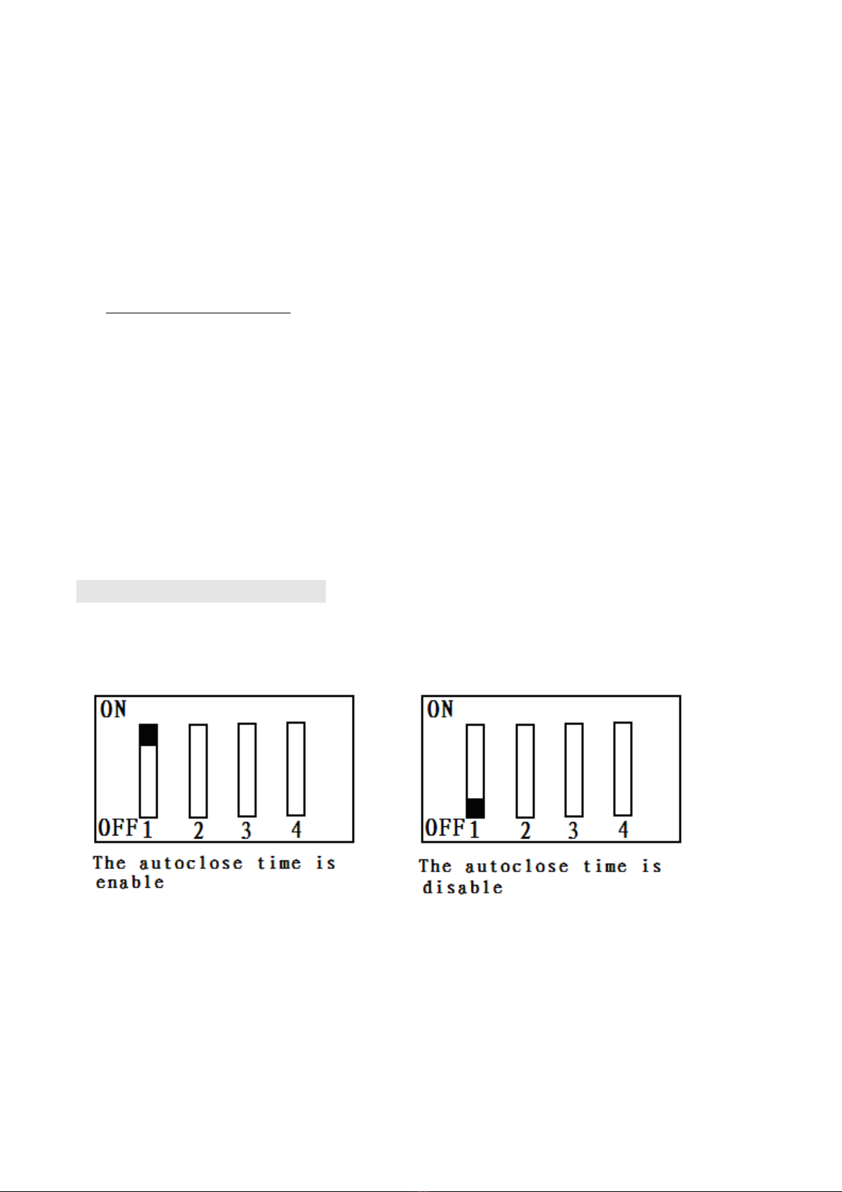
Adjust the DIP switch(see Fig6 and table 1)
Fig6A
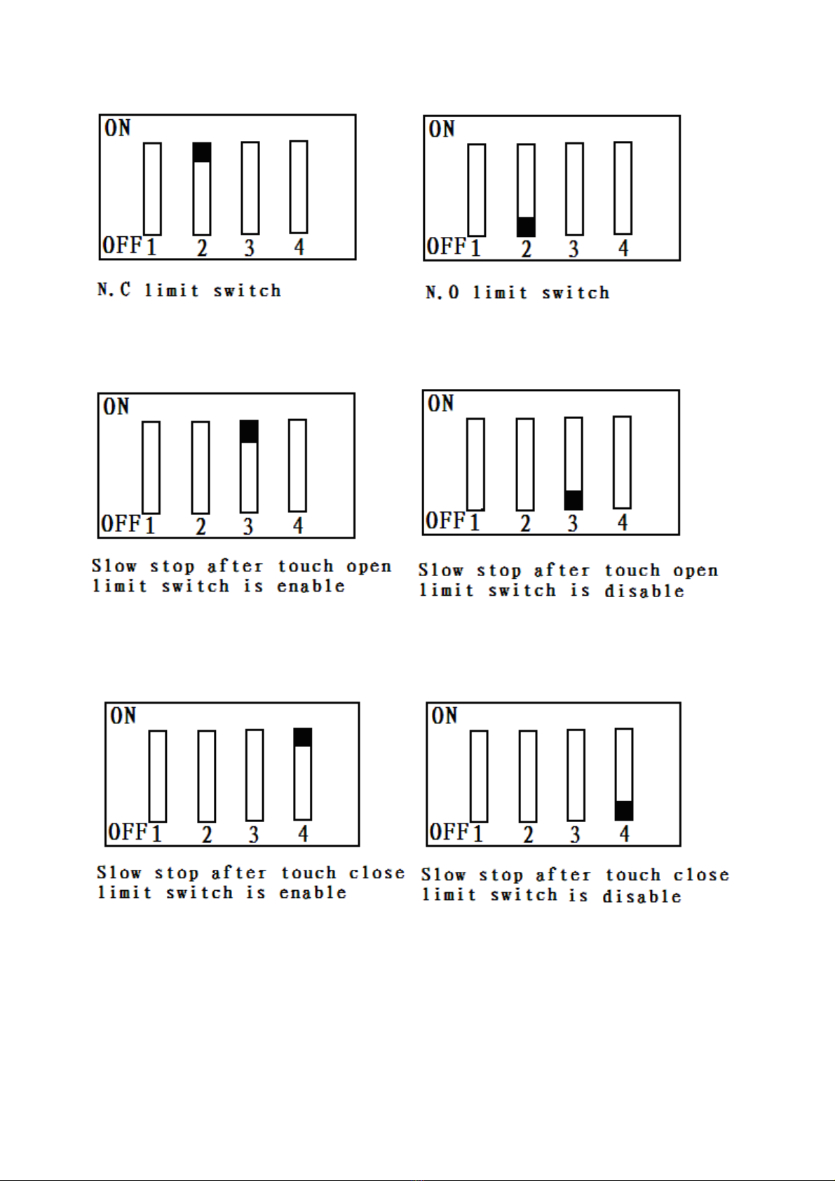
Fig6B
Fig6C
Fig6D
Table 1: DIP switch adjust

DIP DIP-switch Function SET
1ON the Auto-close function is enable,
Rotate VR3 to a just the wi th
OFF the Auto-close function is isable
2ON N.C. limit switch(spring limit)
OFF N.O. limit switch(spring limit)
3ON Slow stop after touch open limit switch is enable
Rotate VR1 to a just the wi th
OFF Slow stop after touch open limit switch is isable
4ON Slow stop after touch close limit switch is enable
Rotate VR2 to a just the wi th
OFF Slow stop after touch close limit switch is isable
NOTE:
(1) You must follow the operating instruction as above any wrong operation
is not allowed during setting. If your device responds to your requested
function correctly you have set the function successfully otherwise
repeat the above setup instruction until your device responds to your
expected function.
(2) If the gate can not be moved please check whether the gate is obstructed
or the gate is too weight.
Table of contents
Popular Gate Opener manuals by other brands

Dea
Dea ghost 200 Operating instructions and warnings

Stanley
Stanley Dura-Max 5400 Series Installation and operation manual

Chamberlain
Chamberlain CSW200UL8 owner's manual

Chamberlain
Chamberlain TC1000 quick start guide

Comunello
Comunello CONDOR 220 Installation and user manual

Topens
Topens CK2500 user manual


