Topens CK2500 User manual
VER 23a
C030685
VER 23b
C030685
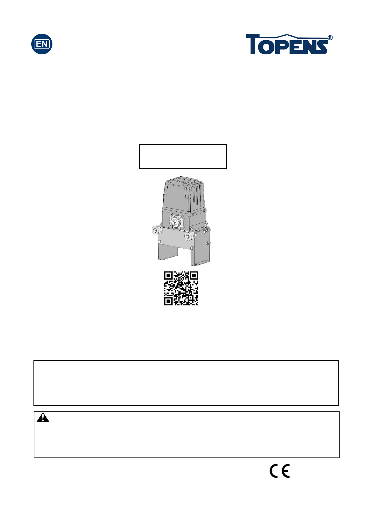
Sliding Gate Opener
User’s Manual
Model:
TOPENS Website
www.topens.com
Email: support@topens.com
Warning: A photocell sensor is included in the package. The photocell must be
installed with the gate opener for SAFETY PROTECTION. The jumper wire between
the PHO & COM terminals (NO.14 & NO.15) MUST BE REMOVED before installing the
photocell.
★Please read and follow all warnings, precautions and instructions before
installation and use.
★Periodic checks of the opener are required to ensure safe operation.
★Save this manual.
CK2500

CONTACT US:
Visit: www.topens.com
Please record the product model, your email address etc.
in the spaces provided below. Refer to this list when contacting TOPENS
for technical service or assistance with your automatic gate opener.
Where did you purchase? (Amazon.com; Amazon.ca: Amazon.co.uk, Amazon.de; Other, Please
Specify)
Order#
Product Model
Purchase Date
Full Name
Phone#
Email Address (VERY
IMPORTANT)
Street Address, Apartment /Unit, City, State /Province, Zip Code
Country/Region
Approximate Gate Weight
(pounds; kg: Other. Please
Specify)
Approximate Gate Length
(feet; meter; Other. Please
Specify)
Did you purchase any
accessories? (Please list
below)
Issue Details
Email Us: support@topens.com
Call: +1 (888) 750 9899 (Toll Free USA & Canada)

Table of Contents
Check Your Gate before Installation.............................................................................................................1
General Safety ............................................................................................................................................1
Preparation for Installation...........................................................................................................................2
Parts List.....................................................................................................................................................4
Accessories Parts (Included in some models, refers to the actual package) ................................................4
Optional Accessories Parts List (Available at TOPENS Store) .....................................................................5
Replacement Parts......................................................................................................................................5
Technical Specifications & Features ............................................................................................................6
Installation Overview ...................................................................................................................................7
Installation of the Opener ............................................................................................................................7
Manual Operation........................................................................................................................................8
Installation of chain and chain brackets .......................................................................................................8
Installation of the Magnets...........................................................................................................................9
Connecting of Power Supply .....................................................................................................................10
Connecting of the Control Board................................................................................................................10
Setting of the Control Board ......................................................................................................................12
How to Program or Erase the Remote .......................................................................................................13
How to Use the Remote to Operate Your Gate Opener..............................................................................14
Wireless Keypad Programming .................................................................................................................14
Troubleshooting.........................................................................................................................................15
Maintenance..............................................................................................................................................16
1
Thank you for purchasing our sliding gate opener. We are sure that the products will be greatly satisfying as
soon as you start to use it.
The product is supplied with a user’s manual which encloses installation and safety precautions. These
should be read carefully before installation and operation as they provide important information about safety,
installation, operation and maintenance. This product complies with the recognized technical standards and
safety regulations.
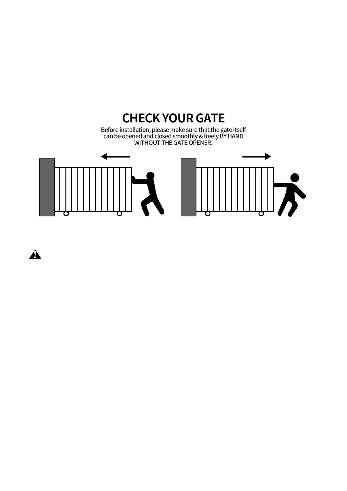
CheckYourGatebeforeInstallation
GeneralSafety
WARNING! An incorrect installation or improper use of the product can cause damage to persons,
animals or properties.
• Scrap packing materials (plastic, cardboard, polystyrene etc.) according to the provisions set out by current
standards. Keep nylon or polystyrene bags out of children’s reach.
• This product was exclusively designed and manufactured for the use specified in the present
documentation. Any other use not specified in this documentation could damage the product and be
dangerous.
• The factory declines all responsibility for any consequences resulting from improper use of the product, or
use which is different from that expected and specified in the present documentation.
• Do not install the product in explosive atmosphere.
• The factory declines all responsibility for any consequences resulting from failure to observe Good
Technical Practice when constructing closing structures (door, gates etc.), as well as from any deformation
which might occur during use.
• Disconnect the electrical power supply before carrying out any work on the installation. Also disconnect
any buffer batteries, if fitted.
• Fit an omnipolar or magnetothermal switch on the mains power supply, having a contact opening distance
equal to or greater than 3,5 mm.
• Make sure a residual current circuit breaker with a 30mA threshold is fitted before the power supply mains.
• Check that earthing is carried out correctly: connect all metal parts for closure (doors, gates etc.) and all
system components provided with an earth terminal.
• Fit all the safety devices (photocells, electric edges etc.) which are needed to protect the area from any
danger caused by squashing, conveying and shearing.
2
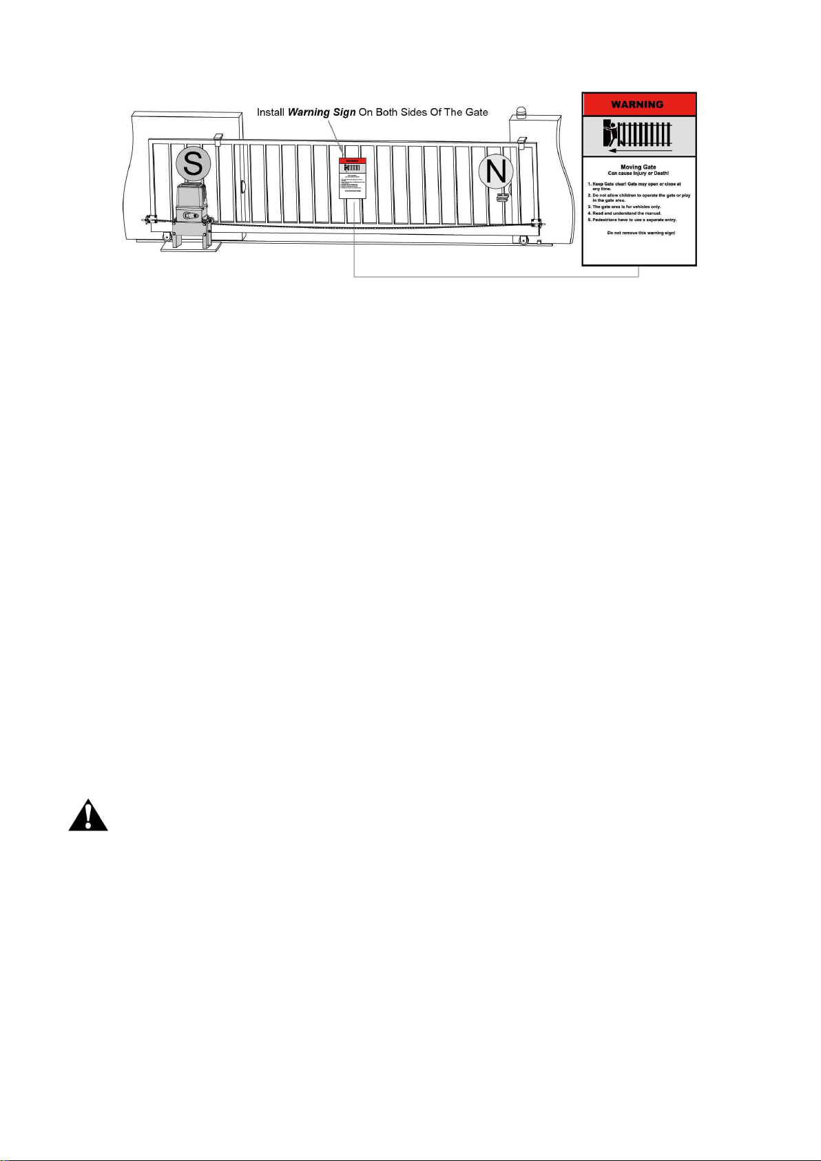
• Position at least one visible indication device, and fix a Warning sign to the structure.
• The factory declines all responsibility with respect to the automation safety and correct operation when
other supplier’s components are used.
• Only use original parts for any maintenance or repair operation.
• Do not modify the automation components, unless explicitly authorized by the factory.
• Instruct the product user about the control systems provided and the manual opening operation in case of
emergency.
• Do not allow persons or children to remain in the automation operation area.
• Keep radio control or other control devices out of children’s reach, in order to avoid unintentional
automation activation.
• The user must avoid any attempt to carry out work or repair on the automation system, and always request
the assistance of qualified personnel.
• Anything which is not expressly provided for in the present instructions is not allowed.
• Before installing the gate opener, check that all moving part as well as the sliding gate is in good
mechanical condition, correctly balanced and opens and closes properly.
• Save these instructions for future use.
Preparation for Installation
Before proceeding to your opener installation, check if your gate structure is in accordance with the current
standards, especially as follows:
The gate sliding track is linear and horizontal, and the wheels are suitable,the gate should be mounted and
moving freely. Check that the structure is sufficiently strong and rigid, Make sure that the gate is plumb and
level. The fence posts must be mounted in concrete. The gate does not bind or drag on the ground.
• The opening and closing gate stops are positioned.
WARNING: Remember that control devices are intended to facilitate gate operation, but can not
solve problems due to any defects or deficiency resulting from failure to carry out correct installation or
maintenance. Take the product out of its packing and inspect it for damage. Should it be damaged, contact
your dealer. Remember to dispose of its components (cardboard, polystyrene, nylon, etc.) according to the
current prescriptions.
Refer to the following Figures for gate installation.
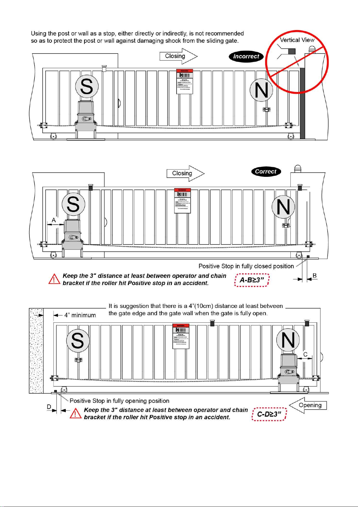
3
In sake of safety, a positive stop must be mounted on the two end of ground track.

4
PartsList
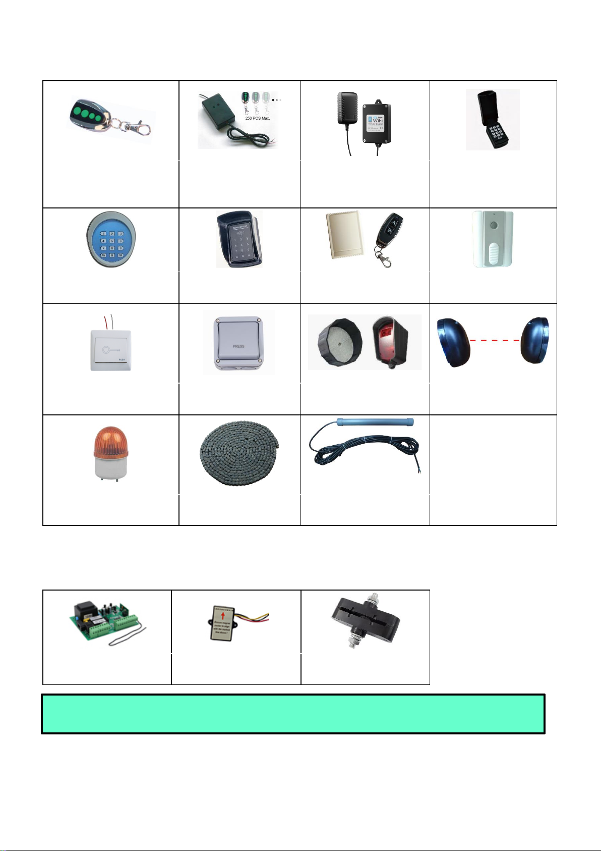
AccessoriesParts (Includedin somemodels,refersto the actualpackage)
5
OptionalAccessoriesPartsList(Available at TOPENS Store)
M12 Remote Control
ERM12 External
Receiver
TC196 Tuya WIFI remote
control
TC188 Universal
Wireless and Wired
Keypad
TKP3 Wireless Keypad
TC175P Wired Keypad
HLR01 HomeLink
Remote Control Kit
TC173 Wireless Push
Button
TC147 Wall Push Button
TC148 Waterproof Wall
Push Button
TRF3 Reflection
Photocell Sensor
TC102 Photo Eye Beam
Sensor
JD110VY Warning Light
LT08B 20 Feet Roller
Chain
TEW3 Vehicle Sensor
Exit Wand
ReplacementParts
ACPYMJ11A-JCQ
Control Board (120V)
PYMJ-CKG Limit Switch
Magnet Assembly (N
pole & S pole)
WARNING: Changes or modifications not expressly specified by this user manual, TOPENS could void
the warranty of this equipment.

6
TechnicalSpecifications& Features
Specifications
CK2500
Power input:
110~120V/60Hz
Motor voltage:
120VAC
Rated power:
1000W
Gate moving speed:
20 cm/s (8 in/s)
Max gate weight:
2600kg (5700lbs)
Environmental conditions:
-20℃~ +50℃ (0°F to 120°F)
Protection class:
IP44
Features:
•Easy to install, and minimum maintenance
requirement
•Midway mode,Quick selection for gate open/close
direction
•Get the desired chain tension by adjusting the
chain bolts.
•Reliable rolling code technology for remote control
•Emergency release key in case of power failure
•Reverse in case of photocell beam obstruction
during gate closing
•Built in adjustable auto-close (0, 30, 60, 90
seconds)
•Built in max. Motor Running Time (MRT) for
multiple safety protection (90 seconds)
•Reliable electromagnetism limit for easy
adjustment
•Can be equipped with wide range accessories

7
Installation Overview
Installationof the Opener
Caution:
*Be sure that the opener is installedin a level and paralleledposition. Improperinstallation could
result in propertydamage, severe injury, and/or
death.
* Before starting installation, ensure that there
is no point of frictionduring the entire
movement of the gate and there is no danger of
derailment.
* Ensure that the safetyside rollersare present.
NecessaryTools: The following tools may be
necessary to install the Gate opener. You will need
screwdrivers, an electric drill, wire cutters and a
wire stripper, a socket set, and possibly access to a
welder.
When install the opener, you should build a
concrete pad to support the base plate of opener in
order to maintain proper stability.
The installation proceeds are as follows:
1. Assemble the Base Plate and fix the Opener to
the Base Plate.
2.Dig ahole for a concrete pad which should be
approximately 60 x 32 x 35cm (24〞x 13〞x 14〞).
It may protrude 10 cm (4”) above ground and 25 cm
(10”) in depth underground. Increase the pad height
if necessary to protect the system fromflooding,
heavy snow etc.
3. Prepare one or more conduits for the electrical
8
cables before pour concrete. Remember that cable conduits have to pass through the hole on the base.
4. Pour concrete and before it starts to harden, check that it is parallel to the gate leaf and perfectlylevel.
5. Mark the position of four expansion anchors according to the position of mounting hole on the base plate.
Double check the marking, move the base plate and drill the 4 holes using a 14mm (9/16”) masonry bit. Put
the 4 expansion anchors (provided) into the holes and firmly tighten.
6. Mount the base plate to the concrete Pad and firmly tighten, enabling the opener is firmly secured on the
concrete pad during the whole gate travel.
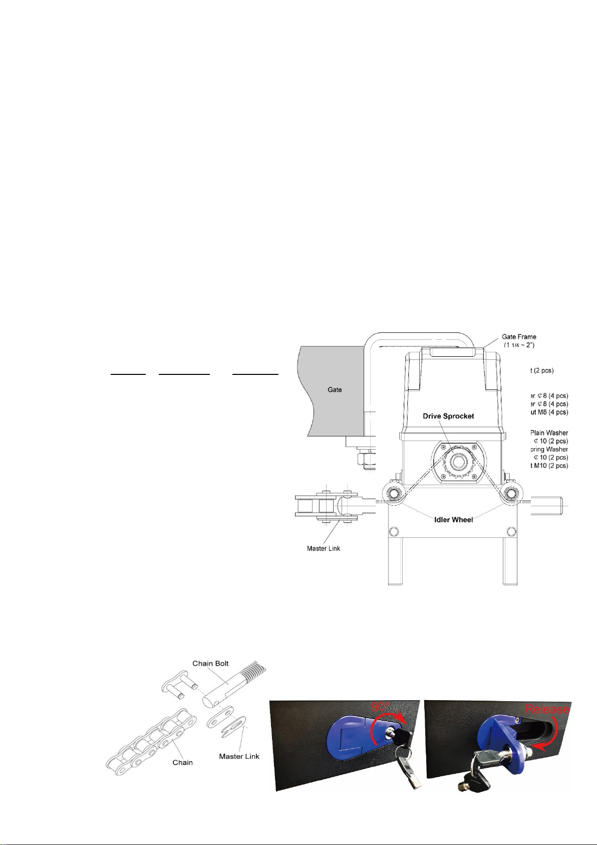
ManualOperation
You can open the gate by manual when power failure. And the opener should be put in the manual
(emergency release) position before fitting the rack, installing the opener and limit switch. The process is as
follows:
Insert the Release Key and turn it in clockwise 90°, then pull the release handle in clockwise 90°to
disengage the clutch between the gear shaft and motor. Now the opener is in the manual operation.
Installationof chainandchainbrackets
1. Chain Brackets
1). Please refer to below chain brackets figure,
which shows “U”bolt, “L”bracket and chain bolt.
Use the “U”bolts (square or round) to attach the
chain brackets to gate frame.
2). If Both the square bolts and round bolts are not
fit for the gate frame, use the appropriate bolts to
attach the chain brackets to gate frame.
2. How to install the chain
1). Place the chain around the top of the idler
wheels and under the drive sprocket in chain box.
2). Connect a chain bolt to one end of chain from
chain box by using master link. Then insert the
chain bolt to the L bracket and fixthem each other
by washers and nuts temporarily. (Nuts will be
further adjusted for a proper chain tension later)
3). Connect second chain bolt with another end of chain from chain
box, then attach bolt to the L bracket on opposite end of gate using the washers and nuts.
4). Make sure that the chain is line up exactly with the position where the chain on the chain idler wheel.
5). Remove the unwanted length of chain. Set appropriated chain tension by adjusting two chain bolts of the
both end.

9
6). The chain brackets must be mounted to the same height as the chain on the idler wheels.
7). Make sure there is 1”distance at least between the wheel cover and the gate after you position the base
plate.
Installationof the Magnets
Before install limit switch, make sure the gate opener is put in manual operation. (the clutch connected with
gear shaft is disengaged) and the mains power supply is disconnected. Position the two Magnet
Components approximately on the gate and move the gate by hand to fix them in place.
Fit magnets bracket
Push the gate fully closed by hand. Locate and install the magnet bracket so that the opener will stop at the

10
desired close position when the close limit switch approaches it.
Push the gate fully open by hand. Locate and install the magnet bracket so
that the opener will stop at the desired open position when the open limit
switch approaches it.
The magnet component with S pole must be installed at left side and the
magnet component with N pole must be installed at right side from the
view inside of property.
Ensure magnet center to align with the marked line above !
The magnets should be 25~30mm (1-1.2”) away from the Limit Switch Box.
If it is too near or too far, the switches will fail to work. Adjust the position of the magnets until the positions of
the opening and closing meet the requirement.
Connectingof Power Supply
WARNING: NEVER connect the gate opener to the power outlet before all the installations have
been done.
The power supply cord should be at least 3×2mm2 (3C×14AWG). Connect the live wire and neutral wire to
the “L” (1#) and “N” (3#) terminal of the power input terminals respectively; and connect the earth wire to
“GR” (2#) terminal of the power input terminals.
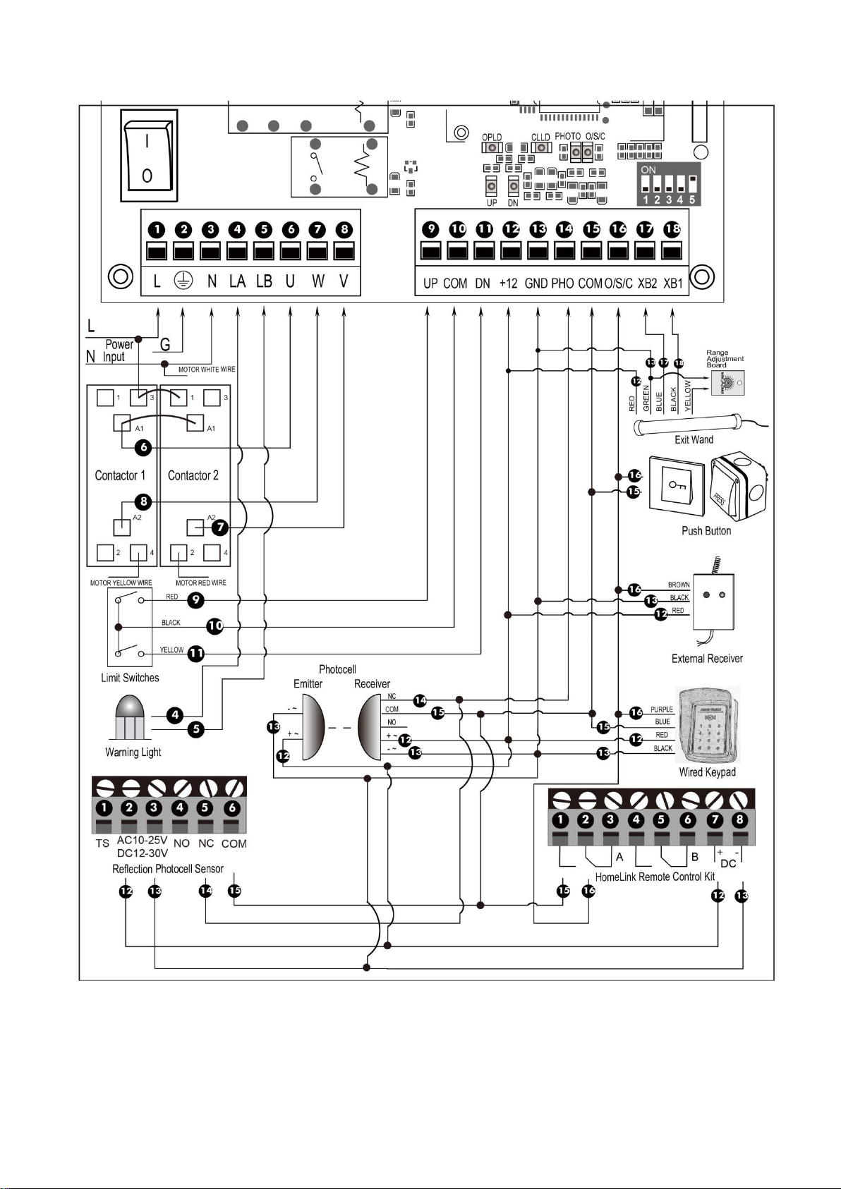
Connectingof the ControlBoard
Warning:Before making any electrical wire connection or/and setting the control board, make
sure that the power switch is OFF.
Warning: A photocell sensor is included in the package. The photocell must be installed with the
gate opener for SAFETY PROTECTION. The jumper wire between the PHO & COM terminals (NO.14 &
NO.15) MUST BE REMOVED before installing the photocell.
1. Contactors
The A1 terminal of both contactors should be wired to the “6” terminal of the control board.
The A2 terminal of contactor1 should be connected into the “8” terminal the control board.
The A2 terminal of contactor2 should be connected into the “7” terminal the control board.
2. Limit Switches
The RED wire of the limit switches should be connected into the “9” terminal.
The BLACK wire of the limit switches should be connected into the “10” terminal.
The YELLOW wire of the limit switches should be connected into the “11” terminal.
3. Warning Light (Included in some models, refers to the actual package)
One wire of the warning light should be connected into the “4” terminal, another should be connected into
the “5” terminal.
4. Photocell Beam System (PBS) (Normally Closed)
Use a 2-core cable to connect the “+ ~” terminal of the photocell’s emitter to the “12” terminal, the “- ~”
terminal to the “13” terminal. Also the “+ ~” and “- ~” terminals of the photocell’s receiver should be
connected to the “12” and “13” terminals in parallel.
Use another 2-core cable to connect the “NC” terminal of the receiver to the “14” terminal, the “COM”
Warning: Improper magnets installation may cause the gate crash into end barrier,
which is very dangerous !
11
terminal to the “15” terminal.
5. Reflection Photocell Sensor (optional)
The “AC10-25V/DC12-30V” terminals of the reflection photocell sensor should be connected to the “12”
and “13” terminals, no matter the polarity.
The “NC” terminal should be connected to the “14” terminal.
The “COM” terminal should be connected to the “15” terminal.
12
6. Push Button (Optional)
The push button should be wired to the “15” and “16” terminals. The gate opener works alternately by
pushing the button (open-stop-close-stop-open).
7. Exit Wand (Optional)
First insert the Adapter BOARD into the CONTROL BOARD, and then connect the wand to the control
board refers to following instruction.
The BLACK wire of the exit wand should be connected into the “#18” terminal.
The BLUE wire of the exit wand should be connected into the “#17” terminal.
The RED wire of the exit wand should be connected into the “#12” terminal.
The GREEN wire of the exit wand should be connected into the “#13” terminal.
The sensitivity adjustment board should be wired to the GREEN wire and the YELLOW wire of the wand. No
matter the polarity.
8. External Receiver (Optional)
The BROWN wire of the external receiver should be connected into the “1 6” terminal.
The BLACK wire of the external receiver should be connected into the “1 3” terminal.
The RED wire of the external receiver should be connected into the “12” terminal.
9. Wired Keypad (12VDC) (Optional)
The RED wire of the wired keypad should be connected into the “12” terminal.
The BLACK wire of the wired keypad should be connected into the “13” terminal.
The PURPLE wire of the wired keypad should be connected into the “1 6” terminal.
The BLUE wire of the wired keypad should be connected into the “15” terminal.
10. HomeLink Remote Control Kit (optional)
The “1” terminal should be connected to the “15” terminal.
The “2” terminal should be connected to the “16” terminal.
The “DC+” terminal should be connected to the “12” terminal.
The “DC-” terminal should be connected to the “13” terminal.
Settingof the ControlBoard
WARNING: Ensure the gate opener is Power Off when you make any adjustment of the gate
opener. Keep away from the gate during you set the gate opener system in case of the unexpected
gate moving. Carefully adjust the DIP switches to avoid
the risk of machine damage and injury or death. Always
ask the help of professional technician /electrician if
you have any question.
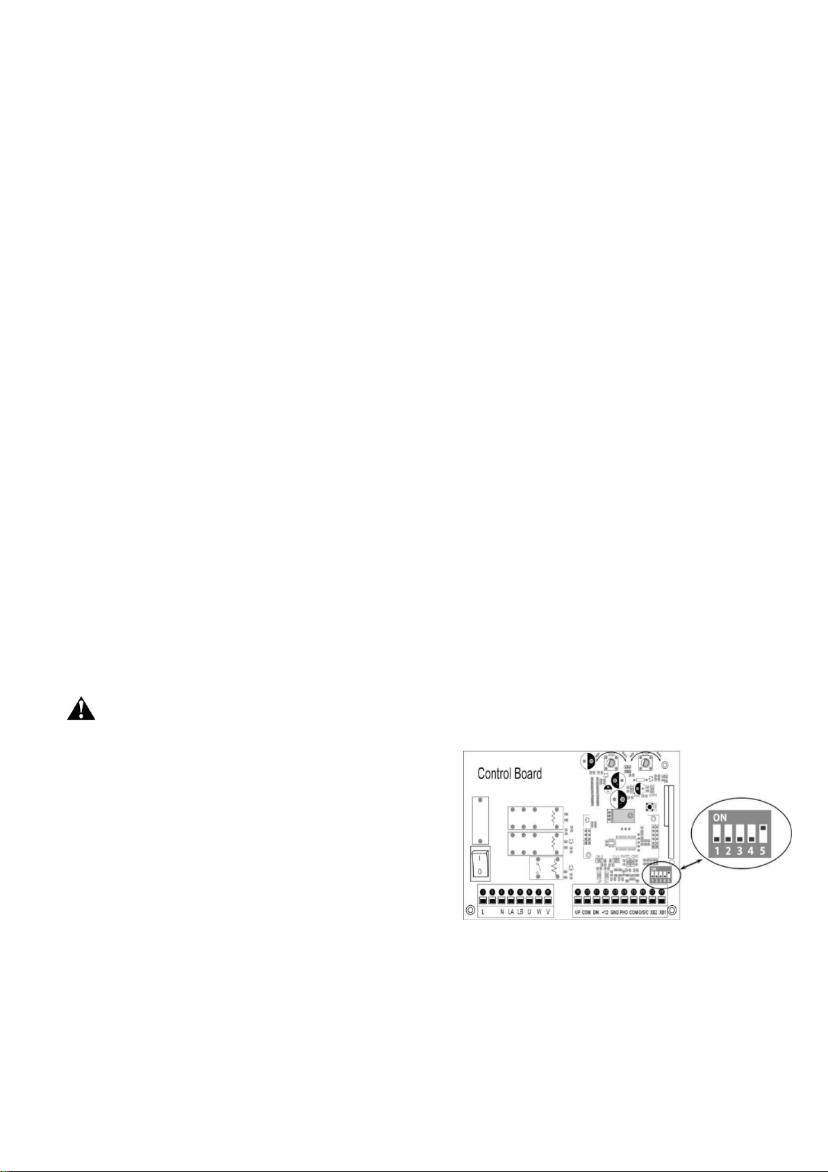
1. DIP Switches
The DIP switches are used to set the running time of the
motor in midway mode, auto close time of the gate opener
and fast change the open/close direction which is
determined by the position of the gate opener installed.
DIP Switch #1–#2: Running time of the motor in Midway Mode
This mode enables user to drive the vehicle through the gate quickly when the gate opens to certain width.
DIP Switch #1: ON – 4 Seconds OFF – 0
DIP Switch #2: ON – 2 Seconds OFF – 0
NOTE: The midway mode function would be disabled if both DIP switches are turned off. Factory
default setting is disabled. The midway mode could be activated by pressing button B of the remote
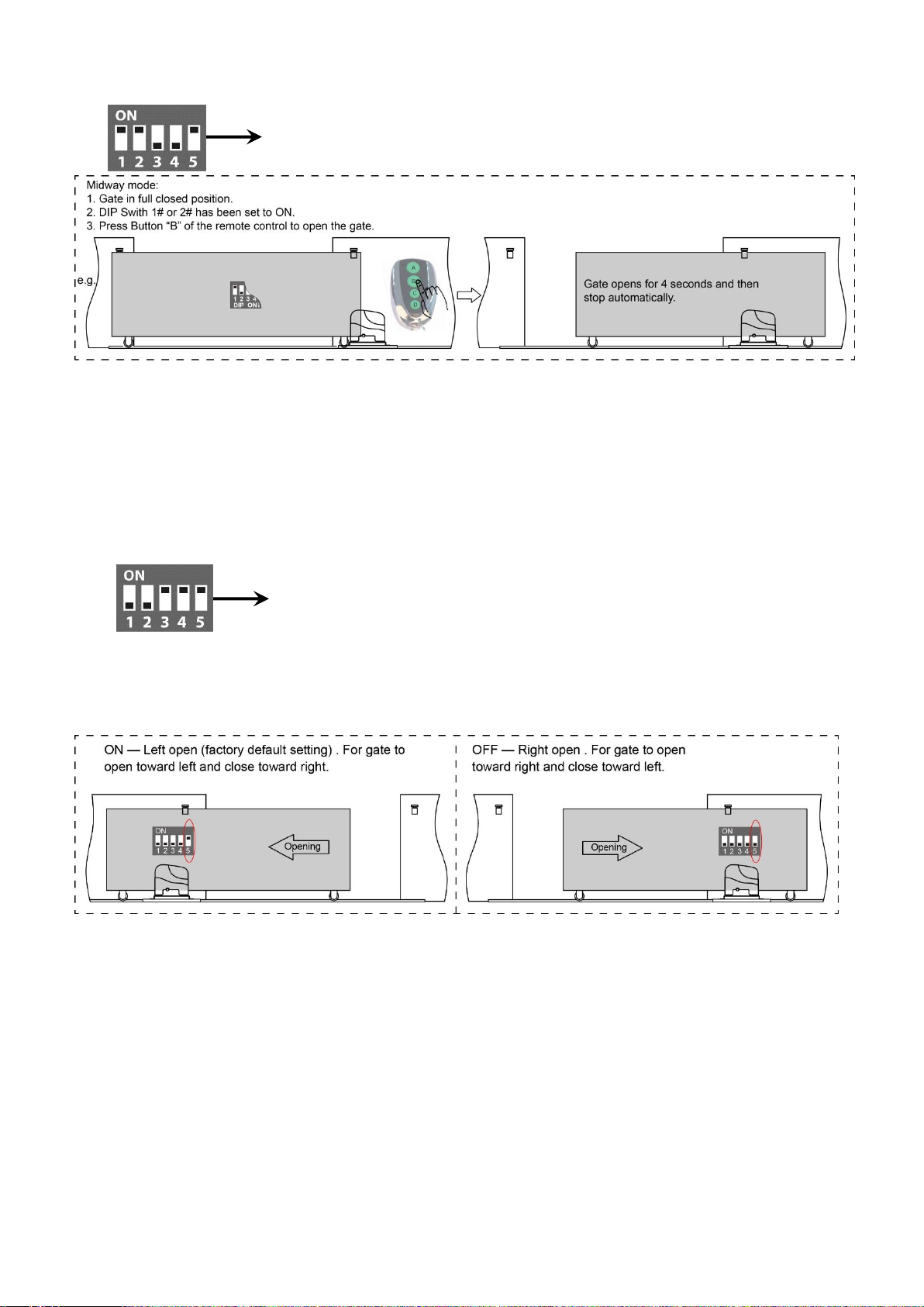
13
control when the gate is in the full closed position.
DIP Switch #3–#4: Auto close time of the gate opener
DIP Switch #3: ON – 30 Seconds OFF – 0
DIP Switch #4: ON – 60 Seconds OFF – 0
NOTE: The auto close function would be disabled if both dip switches are turned to off (factory
default setting).
DIP Switch #5: Left/Right open
ON – Left open (factory default setting).
OFF – Right open. Turn switch OFF to change the opening direction easy if necessary.
How to Programor Erasethe Remote
The remote MUST be programed to the opener BEFORE OPERATING. Please follow the steps to
program the remote.
Activate the opener only when gate is in full view, free of obstruction and properly adjusted. No
one should enter or leave gate area while gate is in motion. DO NOT ALLOW CHILDREN to
operate push button or remote. DO NOT ALLOW CHILDREN TO PLAY NEAR THE GATE.
If you purchase additional remote controls, the gate opener must be programmed to accept the
new remote code.
If you lose one of any remote control, please erase and reprogram all other remote controls to
have a new code for safety.
E.g. Running time of the operator in midway mode is 4+2=6 seconds.
E.g. Auto close time of the gate operator is 30+60=90 seconds.
14
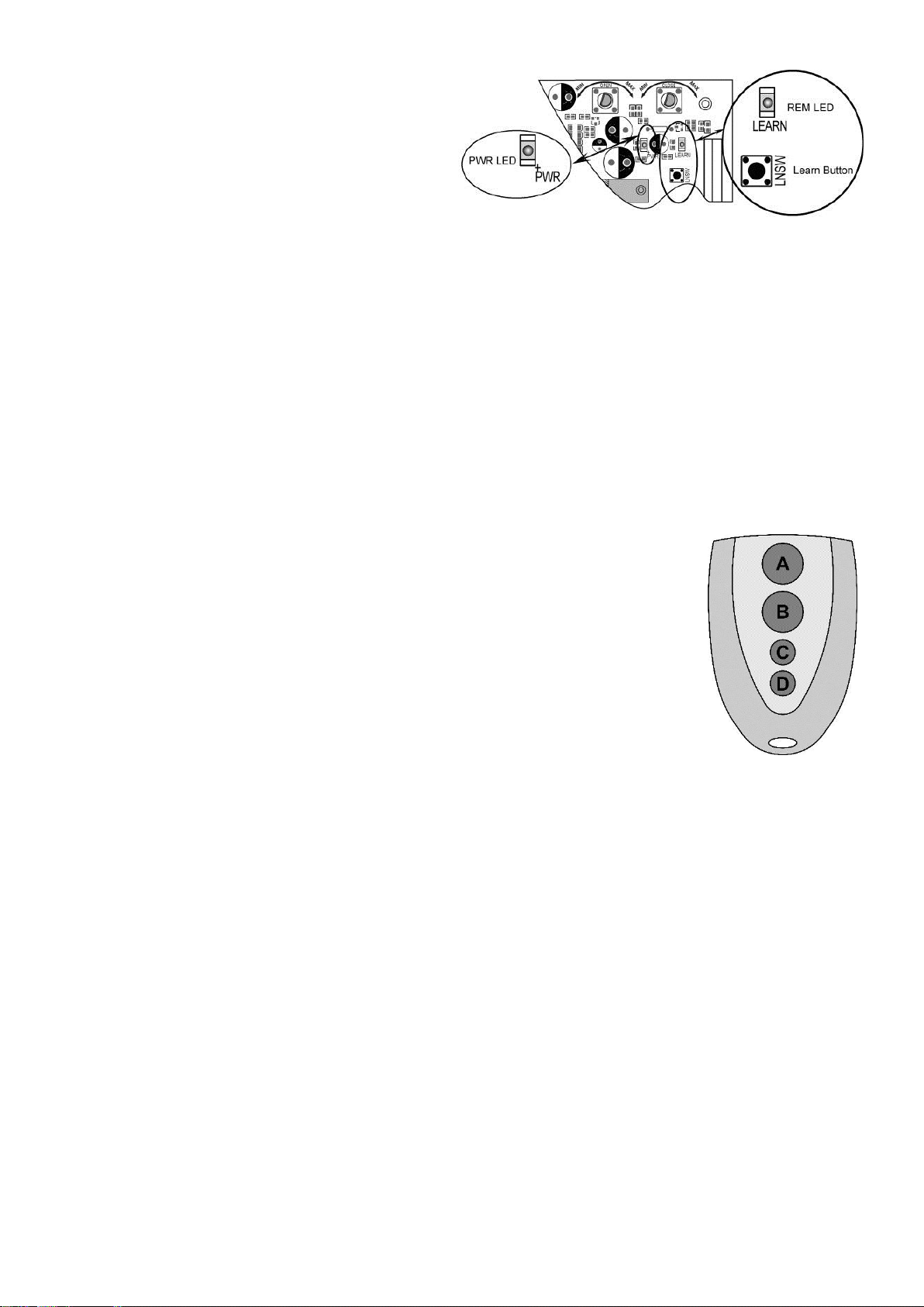
Program the remote
Press and release the learn button, the REM LED
light will be on, then press the key on the remote
two times in 2 seconds, between the two times
HOLD ON FOR A MOM ENT, the REM LED light
will flash for 4 seconds. Now the remote has been
programmed successfully.
Erase all the remote codes
Press and hold the learn button until the REM LED light is off. Now all remote codes have been erased.
NOTE: Max. 8 remotes can be programmed for the opener. An External Receiver (optional) allows
up to 250pcs remotes to be programmed for the opener. TOPENS ERM12 Universal External
Receiver is available at TOPENS Store.
TOPENS ERM12 Universal External Receiver is also compatible with other brand swing gate
opener, sliding gate opener and garage door opener.
How to Use the Remote to OperateYour GateOpener
Each remote has four buttons, from top to bottom are separately A, B, C and D. You may use this remote to
operate as many as 4 sets TOPENS swing gate openers or 1 set TOPENS sliding gate opener and 2 sets
TOPENS swing gate openers.
1. Use this remote to only operate TOPENS swing gate opener A, B, C and D four
buttons share same function once they are programmed with
TOPENS swing gate opener. You may choose any button to program it with our swing
gate opener. Every press of the button is able to active the gate opener to work
alternately (open-stop-close-stop-open).
2. Use one remote to operate TOPENS swing gate opener & sliding gate opener at the
same time
All of TOPENS sliding gate opener have midway mode. Button B is designed to realize
midway function (refer to more details in our TOPENS sliding gate opener manual). So it is must program
button A with sliding gate opener, while you may program either C button or D button with TOPENS swing
gate opener.
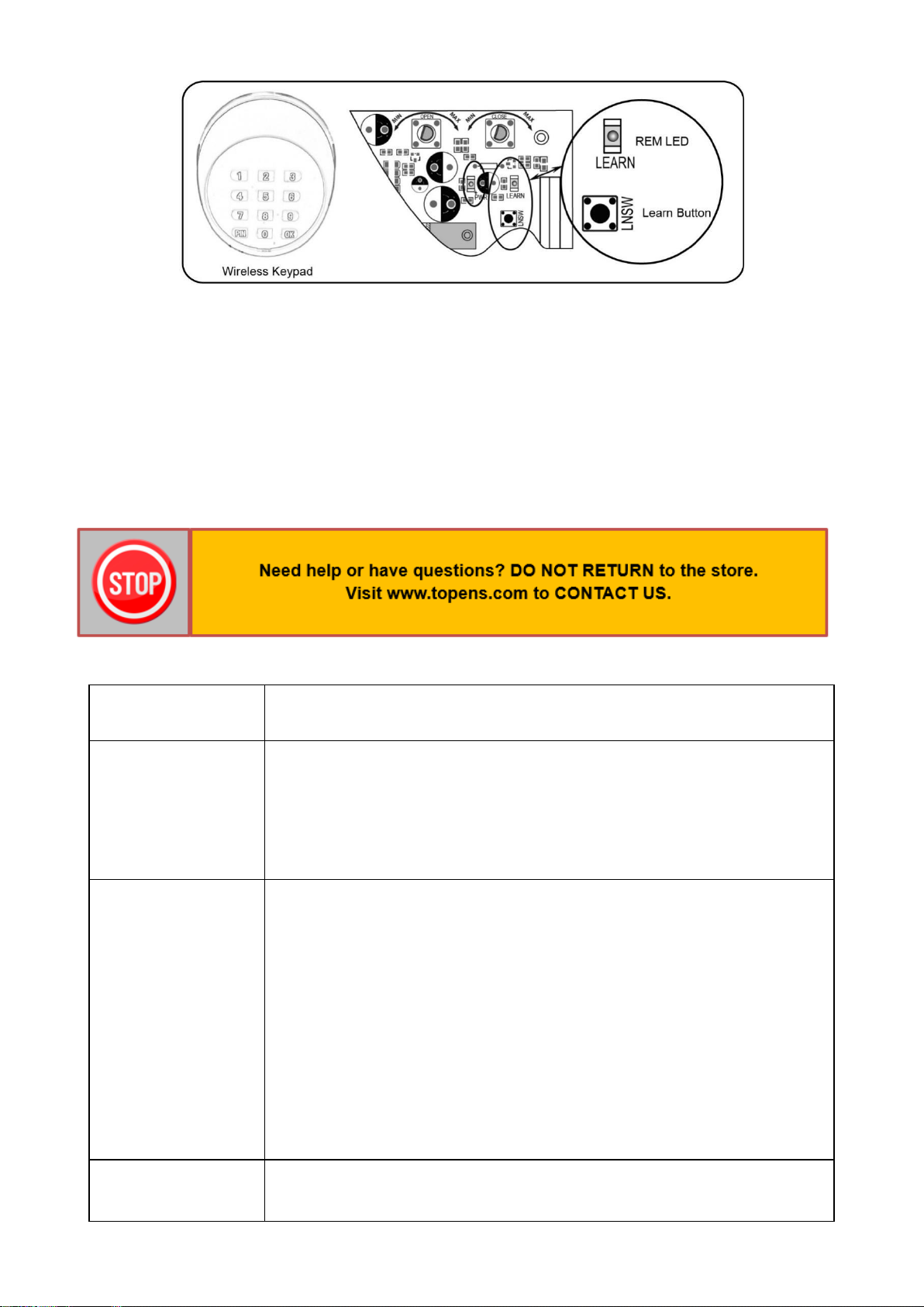
WirelessKeypad Programming
You can follow the below steps to program wireless keypad to the opener. Press the LNSW button until the
REM LED is ON, and then releases the button. Then press "OK" button on keypad and REM LED will flash
for 3 seconds and then be OFF which indicates the keypad has been programmed successfully. You can
use the default password “888888” to operate the opener after programming. You can press “PIN” “8 8 8 8 8
8” and then press “OK” to confirm to operate the opener.
Also you can change the password of the keypad follow the below steps. Press “PIN” and then input the six
digits old password and then press ”PIN” again, the REM LED will be ON. Input the six digits new password
and then press the “PIN” to confirm the new setting, REM LED will flash for 3 seconds and then be OFF
which indicates the password has been changed successfully. You can press “PIN” “6 digits new password”
and then press “OK” to confirm to operate the opener.
15
NOTE: Every step for pressing button during program must be finished within 1 second to ensure successful
programming.
Troubleshooting
Have a multi-meter to check voltage and continuity. Use caution when checking high voltage terminals.
Symptom
Possible Solution(s)
The opener does not
run. Power LED is
OFF.
1. Check the input voltage of the control board. It should be local AC
electricity.
2. The power switch is OFF. Make sure the power switch is ON.
3. Check the fuse in the control board. Replace the fuse if it was burnt out.
4. Check the control board. Replace the control board as necessary.
The opener does not
run. Power LED is
ON.
1. Ensure the remote control has been programmed to the control board
before operating.
2. The thermal protector is working because the high temperature after long
working time. Please wait for 20 minutes to let the motor become cold.
3. Check the installing position of the magnets. The opener would not run if
both of the limit switches are activated by one magnet.
4. Check the limit switch. Remove the wire connection of the limit switch
which is connected to the 9#, 10#, and 11# terminals of the control board and
then try it again. Replace the limit switch if the motor could run in both
directions.
5. Check the control board. Replace the control board as necessary.
Remote control does
not work.
1. The indicator light of remote control is not on. Check the battery in your
remote control. Replace the battery as necessary.

16
Maintenance
Every six months check the following items for proper operation of the unit.
* Lubricate shafts and sprockets.
* Keep opener clean at all times.
* Check and tighten anchors bolts.
* Check for loose or corroded wire
* Ensure the opener is well earthed, and correctly terminated.
2. The distance you use the remote is too far away from the opener. Try it
again closer.
3. Remote control is not suitable for receiver. After making sure the codes are
correct, erase remote controls and then re-program the codes in the device.
4. Check the control board. Replace the control board as necessary.
The gate opens, but
stops and will not
return.
1. Check the installing position of the magnets. The opener would not run if
both of the limit switches are activated by one magnet.
2. Check the limit switch. Remove the wire connection of the limit switch
which is connected to the 9#, 10#, and 11# terminals of the control board and
then try it again. Replace the limit switch if the motor could run in both
directions.
3. Check the control board. Replace the control board as necessary.
The gate can open,
but fails to close.
1. Photocell is obstructed. Remove obstruction.
2. Check the limit switch. Remove the wire connection of the limit switch
which is connected to the 9#, 10#, and 11# terminals of the control board and
then try it again. Replace the limit switch if the motor could run in both
directions.
3. Check the control board. Replace the control board if necessary.
The motor runs but
the gate doesn’t
move.
Ensure the clutch for emergency release is adjusted properly and is not
slipping.

Feedback & Review
Your comments and suggestions are important to us
as they help us provide the best possible service.
Should you have any need to contact us, the info below will help you get in touch:
TOPENS Website
www.topens.com
Contact Us:
E-mail: support@topens.com
Kindly include your Product Model, Purchasing Date & Site, Order #,
and your contact information. All your concerns will be replied within 24 hours.
Tel: +1 (888) 750 9899 (Toll Free USA & Canada)
Table of contents
Other Topens Gate Opener manuals

Topens
Topens CK500 User manual

Topens
Topens CK1200 User manual

Topens
Topens BK800 User manual

Topens
Topens CK2600 User manual

Topens
Topens KD702 User manual

Topens
Topens TC148 User manual

Topens
Topens CK1100 User manual

Topens
Topens RK700 User manual

Topens
Topens AT6132 User manual

Topens
Topens DK1000 User manual

Topens
Topens CK700 User manual

Topens
Topens DKC500 User manual

Topens
Topens CF800 User manual

Topens
Topens DKR500 User manual

Topens
Topens AT602 User manual

Topens
Topens A3131 User manual

Topens
Topens EK700M User manual

Topens
Topens KD902 User manual

Topens
Topens MK1101 User manual

Topens
Topens CASAR HJ4021 User manual


