GB
Check that your gate is in generally good condition (hinges, slide rails and
supports allow movement with the automatic control elements attached).
This movement should be done easily when operated manually.
Fig. 1: Electrical installation preparation (instructions p.10)
Fig. 2: Horizontal positioning of the bracket (instructions p11)
Fig. 3: Vertical positioning of the bracket (instructions p.11)
Mark a line on the pillar 3 cm above the gate’s point of force
Fig. 4: Fix the brackets and install the motors (instructions p.11)
Fig. 5: Assembly of arms (instructions p.11)
Fig. 6: Install the arm and attach the bracket on the gate leaf (instructions p.11)
Fig. 7: Motor unlocked,open the gate leaf, then place the stops (instructions p.12)
Fig. 8: Electrical connection (instructions p.15-16)
Fig. 9: Connection to the electrical network (instructions p.16 and 10)
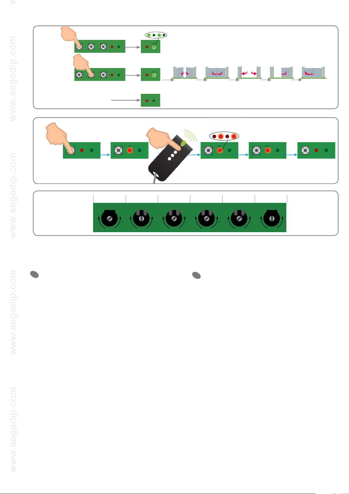
Fig. 10: Automatic practice runtime (instructions p.17)
• Reset for 2s •P1/Set for 2s
Fig. 11: Practice run using the remote controls (instructions p.18)
• P2/Radio during 2s •press the remote control •LD2 flashes.
Fig. 12: Adjustments to optimise the operation of your automatic controls
(instructions p.18)
LED:Adjustment of the backlight’s sensitivity to ambient lighting
FOR: Force
PAU: Set pause time during automatic closure mode
OBS: Reaction time on the obstacle (e.g. for windy areas)
DEL: Closing lag between the overlapping and overlapped gate leaves
OVL: Obstacle detection. Sensitivity
Compruebe el buen estado general de su cancela (goznes o correderas,
soportes que pueden aceptar los elementos del automatismo que deben ator-
nillarse y en movimiento).
El movimiento debe ser fácil cuando se acciona manualmente.
Fig. 1: Preparación de la instalación eléctrica (instrucciones pág. 10)
Fig. 2: Colocación horizontal de la escuadra de fijación (instrucciones pág. 11)
Fig. 3: Colocación vertical de la escuadra de fijación (instrucciones pág. 11)
Trace una raya en el pilar,a 3 cm por encima del punto de fuerza de la cancela
Fig. 4: Fije las escuadras e instale los motores (instrucciones pág. 11)
Fig. 5: Montaje de los brazos (instrucciones pág. 11)
Fig. 6: Instale el brazo y fije la pata de fijación en el batiente (instrucciones pág. 11)
Fig. 7: Con el motor desbloqueado,abra el batiente y después coloque los topes
(instrucciones pág. 12)
Fig. 8: Conexión eléctrica (instrucciones págs. 15-16)
Fig. 9: Conexión a la red eléctrica (instrucciones págs. 16 y 10)
Fig. 10: Autoaprendizaje de los tiempos de recorrido (instrucciones pág. 17)
• Reset durante 2 s •P1/Set durante 2 s
Fig. 11: Aprendizaje de los mandos a distancia (instrucciones pág. 18)
• P2/Radio duante 2 s •pulse el mando a distancia •LD2 parpadea.
Fig. 12: Ajustes para una optimización del funcionamiento de su automatismo
(instrucciones pág. 18)
LED:Ajuste crepuscular de la retroiluminación
FOR: Fuerza
PAU:Tiempo de pausa durante el modo de cierre automático
OBS:Tiempo de reacción con obstáculo (p. ej., caso de zona ventosa)
DEL: Desfase en el cierre entre el batiente recubierto y el que recubre
OVL: Detección de obstáculo. Sensibilidad
Verifique o bom estado geral do seu portão (gonzos ou corrediças, que
os suportes podem aceitar os elementos do automatismo a aparafusar e em
movimento).
O seu movimento deve fazer-se facilmente quando se manobra manualmente.
Fig. 1: Preparação da instalação eléctrica (manual p10)
Fig. 2: Posicionamento horizontal do esquadro de fixação (manual p11)
Fig. 3: Posicionamento vertical do esquadro de fixação (manual p11)
Marcar um traço no pilar, 3 cm acima do ponto de força do portão
Fig. 4: Fixar os esquadros e instalar os motores (manual p11)
Fig. 5: Montagem dos braços (manual p11)
Fig. 6: Instalar o braço e fixar a patilha de fixação no batente (manual p11)
Fig. 7: Motor desapertado,abrir o portão,depois colocar os encostos (manual p12)
Fig. 8: Ligação eléctrica (manual p15-16)
Fig. 9: Ligação à rede eléctrica (manual p16 e 10)
Fig. 10: Auto-aprendizagem dos tempos de percurso (manual p17)
• Repor durante 2s •P1/Configurar durante 2s
Fig. 11: Aprendizagem dos telecomandos (manual p18)
• P2/Rádio durante 2s •premir no telecomando •LD2 pisca.
Fig. 12: Regulações para optimização do funcionamento do seu automatismo
(manual p18)
LED: Regulação crepuscular da retro-iluminação
FOR: Força
PAU:Tempo de pausa durante o modo de fecho automático
OBS:Tempo de reacção sobre obstáculo (caso de zona ventosa, por exemplo)
DEL: Decalagem em fecho entre portão recoberto e a recobrir
OVL: Detecção de obstáculo. Sensibilidade
Controleer de algemene goede staat van uw hek (scharnieren of gelei-
ders, steunen die de te schroeven en bewegende elementen van de automatische
deuropening kunnen dragen)
Het hek moet eenvoudig met de hand bewogen kunnen worden
Fig. 1: Voorbereidende werkzaamheden voor de elektrische installatie
(handleiding blz. 10)
Fig. 2: Horizontale plaatsing van de hoekplaat (handleiding blz.11)
Fig. 3: Verticale plaatsing van de hoekplaat (handleiding blz.11)
Teken een streep af op de steunpilaar,3 cm boven het krachtpunt van het hek
Fig. 4: Bevestig de hoekplaten en installeer de motors (handleiding blz.11)
Fig. 5: Montage van de armen (handleiding blz. 11)
Fig. 6: Installeer de arm en bevestig de bevestigingsbeugel op de vleugel
(handleiding blz. 11)
Fig. 7: Open de vleugel met ontgrendelde motor en breng de aanslagen aan
(handleiding blz. 12)
Fig. 8: Elektrische aansluiting (handleiding blz.15-16)
Fig. 9: Aansluiting op het elektrische netwerk (handleiding blz.16 en 10)
Fig. 10: Auto-learn proces van de slagtijden (handleiding blz.17)
• Reset gedurende 2 s •P1/Set gedurende 2 s
Fig. 11: Auto-learn proces van de afstandsbedieningen (handleiding blz. 18)
• P2/Radio gedurende 2 s •druk op de afstandsbediening •LD2 knippert.
Fig. 12: Afstellingen voor een optimale werking van de automatische deuropening
(handleiding blz. 18)
LED:Afstelling schemerstand van de achtergrondverlichting
KRA: Kracht
PAU: Pauzetijd tijdens de stand automatische sluiting
OBS: Reactietijd bij obstakels (bij winderige zone bijvoorbeeld)
VER:Verschil bij sluiting tussen de bedekte en bedekkende vleugel
OVL: Detectie van obstakels. Gevoeligheid
ES PT
NL
Notice intégrale sur le CD fourni ou à télécharger sur :
Istruzioni integrale sul CD fornito o a trasferire su:
Instrucciones íntegro sobre el CD proporcionado o a cargar a distancia sobre:
Manual integral sobre o CD fornecido ou fazer o download sobre:
Integral manual on provided CD or to download on:
Volledige korte kleurenhandleiding op geleverd CD of om te downloaden op:
Integrale Gebrauchsanweisung auf CD geliefertem oder zu laden auf :
www.cfi-extel.com
D
Überprüfen Sie den allgemeinen guten Zustand IhresTors (Scharniere oder
Schienen,die Baueteile, die die Elemente der angeschraubten und sich bewegenden
automatisierten Betriebseinheit aufnehmen können)
Es muss leicht beweglich sein, wenn es von Hand betätigt wird.
Fig.1: Vorbereitung der elektrischen Installation (Broschüre S. 10)
Fig.2: horizontale Positionierung des Befestigungswinkels (Broschüre S11)
Fig.3: Vertikale Positionierung des Befestigungswinkels (Broschüre S11)
Markieren Sie 3 cm unter dem Kraftangriffspunkt desTors einen Strich auf
dem Pfosten
Fig.4: Befestigen Sie dieWinkel und installieren Sie die Motoren (Broschüre S.11)
Fig.5: Montage des Arms (Broschüre S.11)
Fig.6: Installieren Sie den Arm und befestigen Sie die Befestigungsklaue auf dem
Flügel (Broschüre S.11).
Fig.7: Entriegelter Motor, Flügel öffnen und nachfolgend die Anschläge anbringen
(Broschüre S. 12)
Fig.8: Elektrischer Anschluss (Broschüre S. 15-16)
Fig.9: Anschluss an das Stromnetz (Broschüre S. 16 und 10)
Fig.10: Eigenstudium der Bewegungszeiten (Broschüre S.17)
• Reset während 2 s •P1/Set während 2 s
Fig.11: Erlernen der Funktionsweise der Fernbedienungen (Broschüre S.18)
• P2/Radio 2 s •lang auf der Fernbedienung drücken •LD2 blinkt auf.
Fig.12: Einstellungen zur Funktionsoptimisierung Ihrer automatisierten
Betriebseinheit (Broschüre S. 18)
LED : Dämmerregulierung der Rückleuchten
FOR : Kraft
PAU : Pausenzeitfenster bei dem automatischen Schließmodus
OBS : Reaktionszeit bei Hindernis (beispielsweise inWind ausgesetzten Gebieten)
DEL : Schließverzögerung zwischen bedecktem und deckenden Flügel
OVL : Hindernisdetektion. Sensibilität
Découvrez nos produits sur : www.cfi-extel.com,
& .
• France : Hotline :
0 892 350 069 (0,337€TTC/min)
• Italia :Assistenza Tecnica : +39 02 96488273
assistenza@cfi-extel.com
• España :Asistencia técnica : 902 109 819
sat-hotline@cfi-extel.com
• Portugal : Serviço de apoio ao cliente :
707 201 138