Trafimet Sacit Pantera Operating instructions
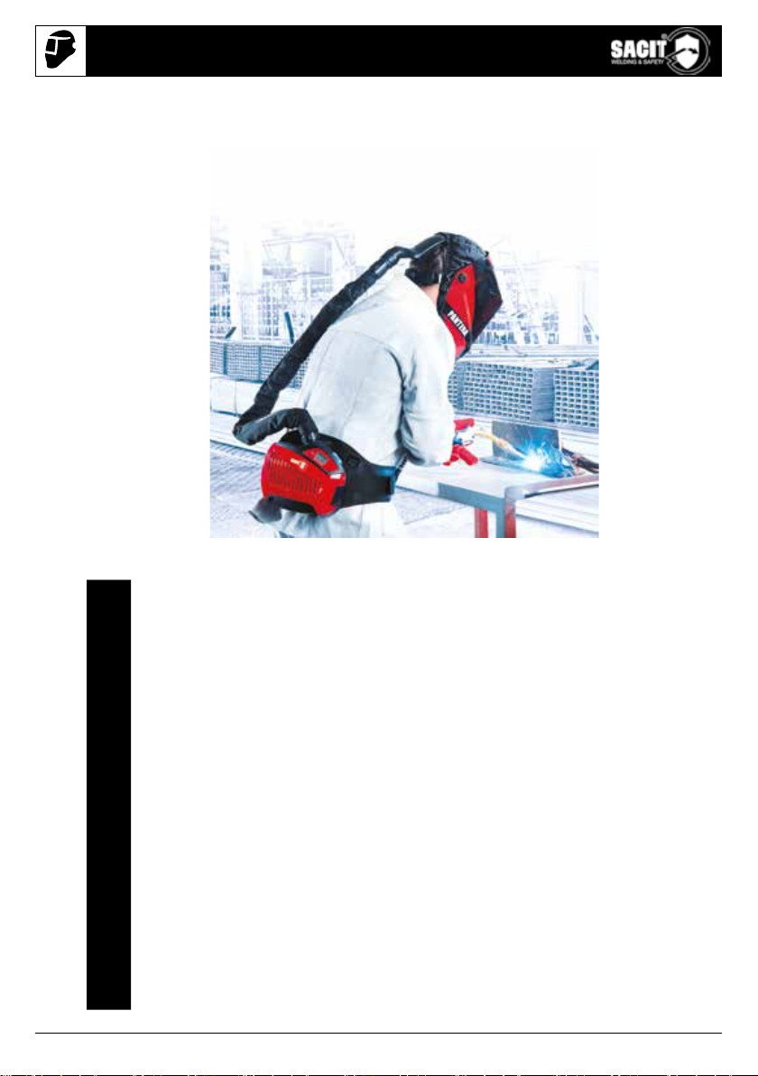
PANTERA AIR SYSTEM
sacit.com
DA Brugs- og vedligeholdelsesmanual
DE Bedienungs- und Wartungsanleitung
EN User and maintenance manual
ES Manual de uso y manutención
FI Käyttö- ja huolto-ohje
FR Manuel d’utilisation et d’entretien
IT Manuale d’uso e manutenzione
NL Gebruikers- en onderhoudshandleiding
NO Bruker- og vedlikeholdsveiledning
PL Instrukcja obsługi i konserwacji
PT Manual de usuário e manutenção
SV Användar- och underhållshandbok
TR Kullanım ve bakım kılavuzu
ZH 用户和维护手册
2
1.
3.
2. 1.
2.
3.
4.
5.
6.
7.
8.
1.
3.
8.
12.
4.
9.
13.
5.
10.
14.
6.
11.
15.
7.
11.
2.
USER AND MAINTENANCE MANUAL

3
4.
5.
6. 7.
1.
1.
1. 1.
2. 2.
3.
3.
2.
2.
5.
4.
4
8.
9.
1.
1.
1. 1.
2. 2.
2. 3. 4.
3.
5.
7.
2.
4.
6.
8.
10. 11.
USER AND MAINTENANCE MANUAL
5
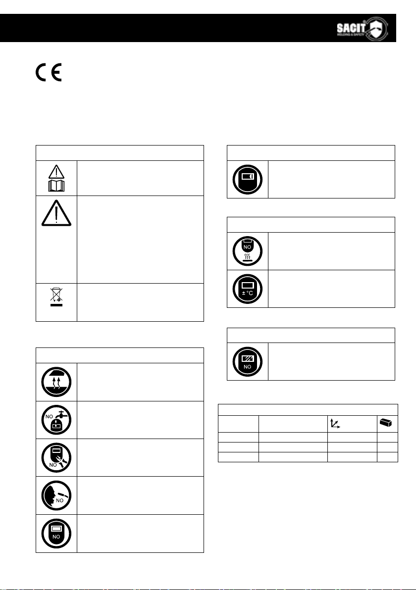
DECLARATION OF CONFORMITY
http://shop.tramet.com/it/Dcue-TrametGroup-Adf3.html
Tramet Group Spa, a duly registered Italian Manufacturing Company, located in Via del
Lavoro, 8 36020 Castegnero (VI), hereby declares that products identied and described
on these pages are in conformity with the Regulation: EU 2016/425 and the standards
EN 175:1997, EN 379:2009, CSA Z94.3, ANSIZ87.1, EN 12941: 1998 +A1:2003+A2:2008
TH3 R SL
WARNINGS
Please read carefully the user and
maintenance manual before operating.
Taking into use and all maintenance
work must be implemented and carried
out by qualied personnel only. The
expression ‹qualied personnel› refers
to operators working in compliance
with the above-mentioned provisions
and standards; said operators must
recognize and properly evaluate
possible risks/dangers related to the
use of welding torches.
Dispose of this product responsibly
after use. All used parts and equipment
must be properly recycled according
to the local requirements/ regulations.
BEFORE WELDING
Make sure to remove any additional
protection foil from both sides of the
protection lens.
MAINTENANCE
Regularly replace the cracked/
scratched protection cover lens.
USE
Never place the helmet or the lter on
hot surface.
Use only within the temperature range
of -10°C (14°F) – +60°C (140°F)
SAFETY PRECAUTIONS
Fumes are hazardous for health.
Operate under a hood or in ventilated
areas only.
Do not immerse the auto-darkening
lter in water. Do not expose the lter
to liquids and protect it from dirt.
Do not modify or implement structural
changes to the helmet.
Keep the torch turned away from
yourself and others.
If the welding lter doesn’t darken
when the arc is ignited, stop welding
immediately and contact your
supervisor or your dealer.
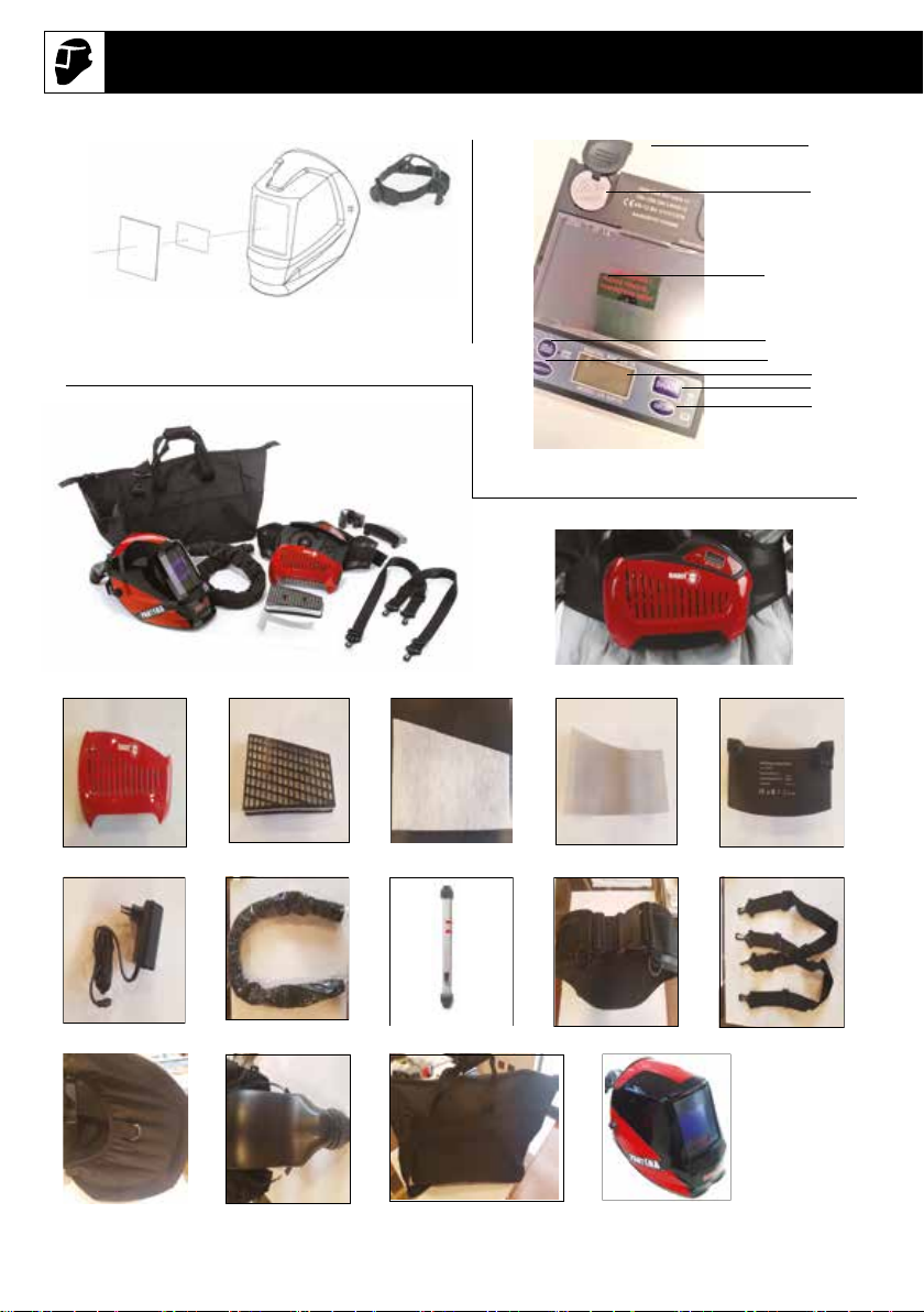
Pack contents
PANTERA Autodarkening mask (see g. 1)
CODE DESCRIPTION
LVE000238 Outside protection plate 114x133x1 mm 5
LVE000237 Inside protection plate 106x66x1 mm 5
VCE000010 Ergonomic headgear 1
LCD Filter included (see g. 2)
1. Battery cover (2 pcs)
2. Battery (2 pcs)
3. Display
4. WELD/GRING button
5. SENSITIVITY button
6. LCD display
7. SHADE button
8. DELAY button

6
EN USER AND MAINTENANCE MANUAL
Introduction
This manual is made of 2 parts:
1 - “PANTERA” AUTODARKENING MASK
2 - COMPLETE “PANTERA AIR SYSTEM”
1. PART 1 - “PANTERA” AUTODARKENING MASK
1.1 Summary
The PANTERA autodarkening welding mask is a new generation welding helmet integrating some
of the most innovative technologies such as digital LCD, optoelectronics detection with 4 sensors
and very wide viewing area, solar power and litium batteries, microelectronics, and True Color ADF
technology.
The PANTERA automatic welding mask is equipped with an ADF lter with digital regulations, for an
easy and fast adjustment of all functions.
The main functions are: MIG/MAG, TIG, PLASMA CUTTING, GOUGING and GRINDING.
The mask ergonomy has been studied to guarantee an excellent protection of head/neck/ears.
WARNING
Read and understand all instructions before using.
• Be sure that the DIN of the welding mask lter is the correct shade number for your application.
• The PANTERA autodarkening welding mask and lter are not suitable for overhead welding
applications, laser welding, or laser cutting applications.
• The PANTERA autodarkening welding mask is designed to protect the eyes and face from
sparks, spatter, and harmful radiation under nor-mal welding conditions.
• The PANTERA autodarkening welding mask will not protect against explosive devices or
corrosive liquids. Machine guards or eye splash protection must be used when these hazards are
present.
• Impact resistant, primary eye protection, spectacles or goggles that meet current ANSI
specications, must be worn at all times when using this welding helmet.
• Avoid work positions that could expose unprotected areas of the body to spark, spatter, direct
and/or reected radiation. Use adequate protection if exposure cannot be avoided.
• Before each use, check that the protection plates are clean and that no dirt is covering the
sensors on the front of the lter.
• Inspect all operating parts before each use for signs of wear or damage.
• Any scratched, cracked, or pitted parts should be replaced immediately.
• Do not make any modications to either the welding lters or helmet, other than those specied in
this manual.
► Do not use any replacement parts other than those specied in this manual,
Unauthorized modications and replacement parts will void the warranty and expose the
user to the risk of personal injury.
►If this lens does not darken when the arc is ignited, stop welding immediately and contact
the manufacturer’s representative.
►Do not immerse this lter in water: this model is not water proof.
►Do not use any solvents on any lter or helmet components.
► The recommended operating temperature range for welding lter is -5°C (23°F) – +55°C
(131°F). Do not use this device beyond these temperature limits.
• Failure to follow these warnings and/or failure to follow all of the operating instructions could
cause severe personal injury.

7
1.2 Characteristics
PANTERA automatic welding helmet is equipped with an auto-darkening lter with 4 sensors, digital
display and a wide view area.
Before activation the lter shade is DIN 4, so that the operators may clearly observe the work surface
clearly.
Once the arc is ignited, the lter darkens automatically. When the arc goes out, the lter will becomes
transparent again. The mask is equipped with DIN 9-13 darkness adjusting. The switching time from
light to dark is about 0.08 ms. The switching time from dark to light (DELAY) may be set up within 0.1-
0.9 second. The operator can also adjust the SENSITIVITY and select the operation method WELD or
GRIND.
PANTERA automatic welding mask gives the operators complete protection against UV/IR even in the
lter’s light state. The UV/IR protection level is up to DIN15 at all times. The power is provided by solar
cells and replaceable battery.
The mask is equipped with 4 sets of photo sensors to sense arc light. In addition, the mask is also
provided with an outer protection plate made of high polymer materials.
The plate is wear-resistant, thermostable, and has no dregs-sticking, thus a very long service life.
1.3 Main specications
Filter dimension 114 x 133 x 9.5 mm
View area 100 x 60 mm
Light shade number DIN 4
Dark shade number DIN 9-13
UV/IR protection up to up DIN15
Time from light to dark 0.08 ms
Time from dark to light 0.1-0.9 s
Sensitivity adjustable stepless
Power supply solar cells & replaceable battery
Operating temperature -5°C (23 °F) – +55°C (131°F)
Warranty 2 years as per sales conditions
Grinding function Yes
Optical classication 1/1/1/1
1.4 Method of operation
1. Assemble the mask as shown in the construction and assembly gure.
2. The power supply of the PANTERA auto-darkening mask is provided by solar cells with
two lithium batteries.
3. Darkness selection Adjust to the optimum darkness as needed. Press the SHADE button
to choose the Shade number range 9-13 according to the current welding process.
4. Delay time selection Press the DELAY button to choose the Delay option from 1 to 5,
0.1~0.9 second.
5. Sensitivity selection Press the SENSITIVITY button to choose the Sensitivity option to
alter the sensitivity to ambient light.
Turn to 1: The photosensitivity changes to be lower. Suitable for high amperage welding
and welding in bright light conditions (lamp light or sun light).
Turn to 5: The photosensitivity changes to be higher. Suitable for steady arc process such
as TIG welding.

8
EN USER AND MAINTENANCE MANUAL
6. Because the shapes of users’ heads vary from person to person. The work position and
the observing angle is dierent, operator may adjust the headband adjusting button 15 and
the segmental positioning plate 16 to select an appropriate observing angle.
By pushing and turning the adjustment screw 11, the perimeter of the head band can be
adjusted.
7. Grind function Press the WELD/GRIND button to choose the Grind option. The grind
ash light will ash at the same time. To avoid any harm to eyes, do not conduct welding
while on grinding mode.
8. Battery indicator in the up right corner there is a battery indicator. We suggest replacing
the battery when the indicator ashes.
1.5 Points for attention
1. Make sure that the helmet is used in correct condition and check it according to WARNING
content.
2. There is a liquid crystal-valve in the lter. Although it has inner and outer protection plate, it
is important to avoid heavy knocks to keep it intact.
3. The outer protection plate of helmet should be periodically inspected and cleaned to keep
it clear. In case break, crack, pitting or more serious inuencing vision eect occurs, the
plate must be replaced.
4. In order to operate more eciently and safely, please select correct dark shade number.
5. If the lter is not a water-proof model, please pay attention to protect it from water.
6. Make sure that the arc light can be completely received by the sensor, if not, the lter will
be in light state or unstable in darkness and may cause injury to the user.
7. Please use the automatic lter at temperature between -10°C (14°F) – +55°C (131°F).
8. Please don’t disassemble the lter, any problems arising, please contact our company or
agent.
1.6 Marking
4Clear DIN level
9-13 Shade DIN level
SA Manufacturer
1Optical class
1Diusion of light class
1Variations in luminor transmittance class
1Angular dependance class
EN379 CE Directive reference and conformity mark
9
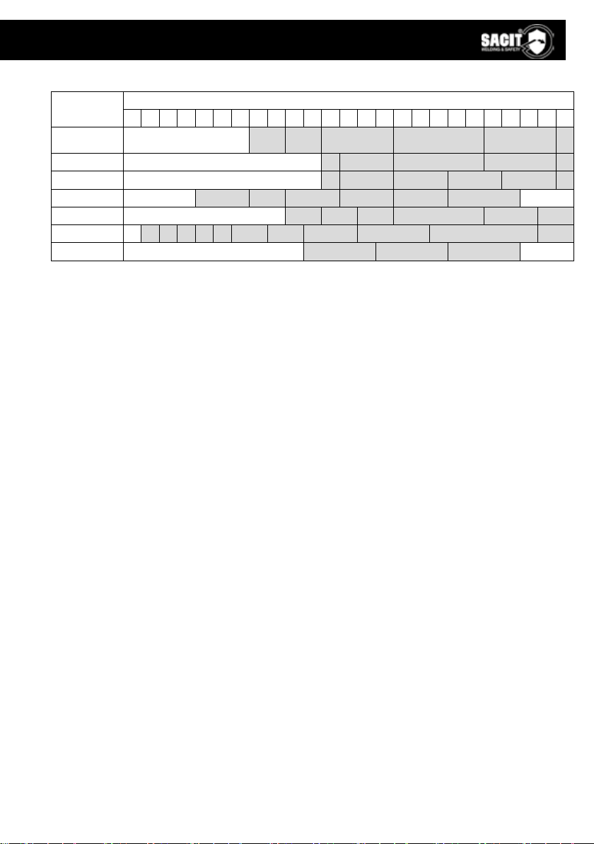
1.7 Recommended shade number according to EN 379
Welding
process
Amperes
0.5 1 2.5 5 10 15 20 30 40 60 80 100 125 150 175 200 225 250 275 300 350 400 450 500 550
Covered elec-
trodes 9 10 11 12 13 14
MIG (steel) 10 11 12 13 14
MIG (light alloys) 10 11 12 13 14 15
TIG 9 10 11 12 13 14
MAG 10 11 12 13 14 15
Plasma welding 56789 10 11 12 13 14 15
Plasma cutting 11 12 13
2. PART 2 - COMPLETE PANTERA AIR SYSTEM
2.1 Introduction
Pantera Air System is a combined face and respiratory protection device for increased safety and
comfort during welding. Please read these instructions carefully before unpacking.
The respiratory protection system must not be used:
• In a dangerous environment for the user’s health and safety, an environment with an oxygen level
below 17% or containing unknown substances.
• In conned or non-ventilated environments such as curves, etc.
• Near ames or projections.
• In an explosion risk zone.
• In a very windy zone.
• If the lter is not installed.
2.2 Approvals
The system complies with the requirements of PPE Regulation 2016/425 and European Standard EN
12941: 1998 +A1:2003+A2:2008 TH3 R SL. The Respiratory System is designed to provide a supply
of ltered air via a breathing tube to a welding headpiece. The equipment can be used in environment
that requires a class TH3 P breathing protection device. It protects against particulate contamination.
All components used in Respiratory System must be manufacturer approved parts, and must be used
in accordance with the instructions in this manual.
1. The approval is not valid if the product is incorrectly used together with non-approved parts
or components.
2. Only the particle lter and pre-lter can be used together with this system. Filters from
other manufacturers should under no circumstances be used.
2.3 Warning and limitations to use
Before each use, inspect the Respiratory System for damage and verify that it operates properly.
Before using the Respiratory System, test air ow to verify it is providing an adequate volume of air.
Always wear the Respiratory System and do not remove the head top or turn o the air lter unit until
outside the contaminated area. Otherwise, there is a risk of high concentration of CO2 and oxygen
level in the head top will fall, thus little or no protection is given.
If you are not sure about the concentration of pollution, or about equipment performance, ask the
industrial safety engineer.

10
EN USER AND MAINTENANCE MANUAL
The manufacturer is not responsible for injury due to the following incorrect use or incorrect choice of
equipment.
Warning:
• The respiratory devices should be use with well-trained personal and qualied person only.
• Before using the devices ensure you have understood that at very high work rates the pressure in
the device may become negative at peak inhalation ow.
• Before and during using the devices, attention shall be drawn to possible incorrect use and, where
appropriate, the possibility of looped hoses and/or cables becoming caught up.
• Before or during using the devices if the devices in the power-o state little or no respiratory
protection is to be expected, and that this is considered to be an abnormal situation.
• Please leave the work place and remove the headgear, when the devices in the power-o state a
rapid build-up of carbon dioxide and depletion of oxygen within the hood may occur.
• The lters shall only be tted to the turbo unit and not directly to the helmet/hood.
• The user should not confuse the markings on a lter relating to any standard other than EN 12941
with the classication of this device when used with this lter.
• DO NOT use with the blower unit switched o.
• DO NOT use in an atmosphere that is immediately hazardous to user hygiene or health and/or
has oxygen content of less than 19,5% or contains unknown substances.
• DO NOT use in an explosive atmosphere.
• DO NOT use in conned spaces or areas of poor ventilation
• DO NOT use in high winds.
• DO NOT alter or modify in any way.
• DO NOT touch any of the moving parts.
• DO NOT allow water or other liquids to enter the impeller chamber, the lter or battery
compartment.
2.4 Part list (see g. 3)
Code Description Picture
MSC000441 PANTERA AIR SYSTEM 1
MU0361 BLOW UNIT SACIT AIR SYSTEM 2
BW0755 FILTER COVER 3
SPL000386 PARTICULATE FILTER 4
SPL000381 PRE-FILTER 5
SPL000382 SPARK ARRESTOR 6
SPL000383 RECHARGEABLE BATTERY LI-ION 7
SPL000394 240V BATTERY CHARGER 8
SPL000392 BREATHING TUBE (0.6 m) WITH CLOTH 9
SPL000387 ASSEMPLED FLOW METER 10
SPL000385 BELT + SHOULDER HARNESS 11
SPL000393 THROAT PROTECTION 12
VCE000698 HEADGEAR WITH AIRDUCT + HOLE 13
SPL000389 CARRIER BAG FOR SACIT AIR SYSTEM 14
PANTERA AUTODARKENING MASK 15
LVE000238 OUTSIDE PLATE 114X133X1 mm 16
LVE000237 INNER PLATE 106X66X1 mm 17

11
2.5 Unpacking/Assembly
Check that correct number of components has been supplied, as in gure 3-1. Check that the
apparatus is complete, undamaged and correctly assembled. Any damaged or defective parts must be
replaced before use.
If any of the above components are not included in your kit, please contact the supplier immediately.
2.6 Filter replacement (see g. 4)
1. Remove the lter cover by pressing in the latch of the lter cover.
2. The lter cover is released.
3. Remove the used lter by lifting it out from the lter cover. Remove the used lter by lifting
it out from the lter cover.
4. Remove the pre-lter.
5. If the ltration grill is dirty, clean it (blower).
The pre-lter and lter expected lifetime is 12 months. When under intensive use, check the lter
cleanliness periodically and if needed, change them more often than every 12 months.
2.7 Installing the battery/Charging (see g. 5)
1. Slide the battery towards the back of the ltration unit.
2. Make sure that the battery is locked in position.
3. The battery can be charged on the ltration unit or separately.
The battery is partially charged when delivered. It must be charged at a 100% before the
rst use. It is recommended to charge the batteries at a 100% before each use.
The charger must not be used for anything else than it was designed for. Do not charge
the battery in a potentially explosive area. The charger must only be used indoors.
The charger regulates the charge automatically, once the battery is fully charged, it will
maintain it at a 100% (oating charge). The charge time is 3 to 4 hours.
The battery will discharge itself after long storage periods. Always charge the battery if the
device was stored for more than 15 days. Once the battery is new or has been stored for
more than 3 months, charge it and discharge it at least twice in a row to reach the nominal/
rated charge capacity.
Battery charge:
1. Connect the charger to the mains.
2. Connect the battery to the charger. The connector is above the battery.
3. The state of charge is displayed via a red LED on the mains charger.
4. Once the charge is nished, the oating charge becomes active: the red LED switches o
and a green LED switches on.
5. Disconnect the charger from the mains (do not keep the charger plugged to the mains if
it’s not in use).
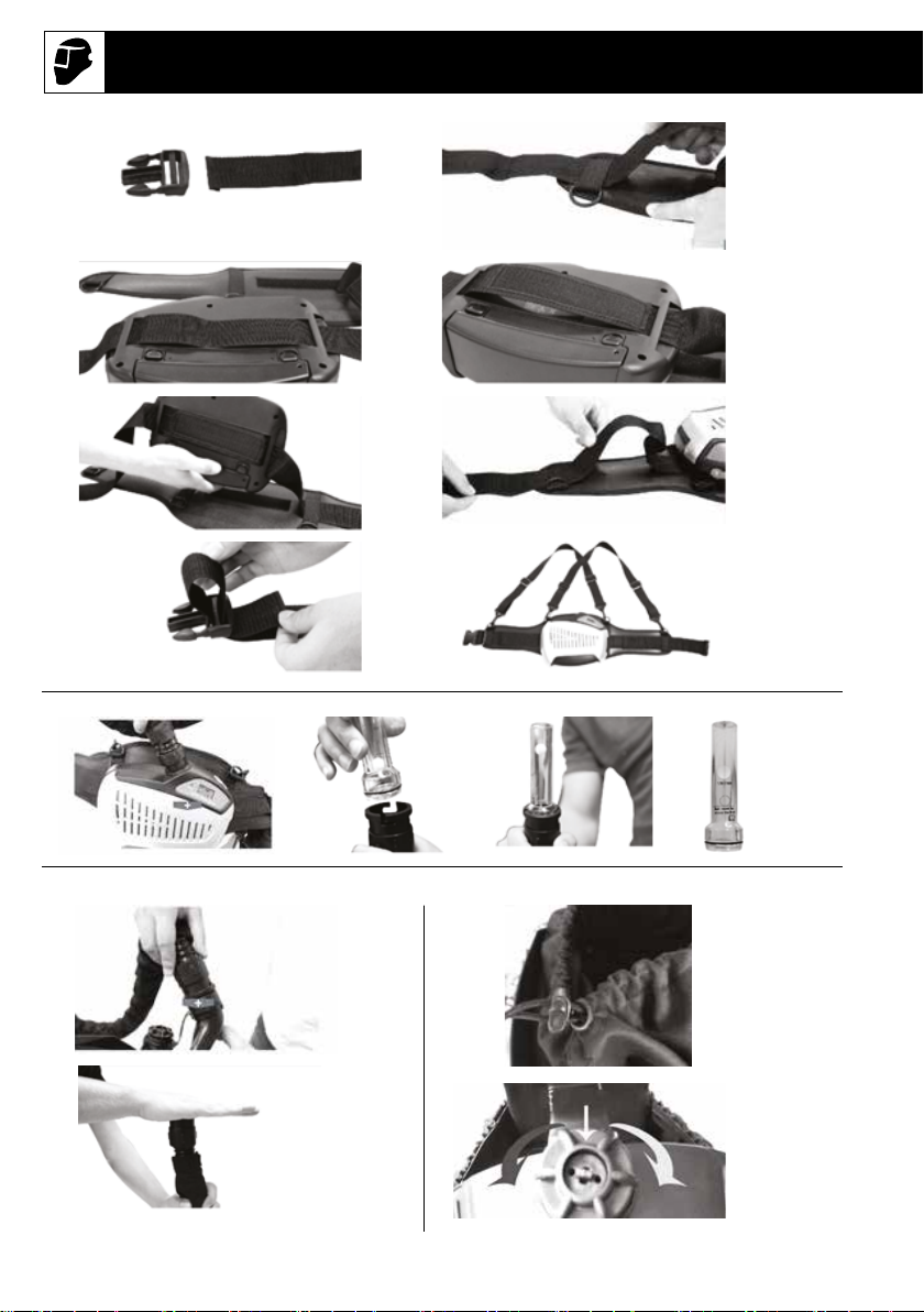
2.8 Installing the respiratory system on the belt (see g. 8)
1. Remove the belt’s release buckle.
2. Remove the fastening belt from the waist connector’s 2 belt loops
3. Make the fastening belt pass through the respiratory system’s 2 belt loops.
4. Position the Velcro® between the 2 loops.
5. Flip the ltration system and attach the Velcro® on the belt.
6. Put the fastening belt back through the 2 belt loops.

12
EN USER AND MAINTENANCE MANUAL
7. Put the buckle back.
8. Attach the harness to the belt’s 4 plastic rings.
Make sure the belt is securely fastened.
2.9 Connecting the tube (see g. 6)
1. Connect the air tube to the respiratory system and twist it clockwise to lock its position.
2. Connect the other end of the tube to the headgear in the same way.
1. Check that the respiratory tube is strongly connected. If the tube is broken, replace it.
All components must be installed/ used in accordance with this manual if the equipment is to oer the
specied protection. If any component is missing, or if anything is not clear, contact the supplier.
2.10 Adjust airow rate (see g. 7)
The airow rate in the middle and both side of the airduct outlet can be adjusted by a switch
assembled on airduct according to personal preference.
1. Counter-clockwise adjust the switch, airow rate from middle outlet will be 20% and both
side outlet will be 80%
2. Clockwise adjust the switch, airow rate from middle outlet will be 80% and both side
outlet will be 20%
All components must be installed/used in accordance with this manual if the equipment is to oer the
specied protection. If any component is missing, or if anything is not clear, contact the supplier.
3. Before use/Fitting (see g. 9)
3.1 Air ow test
1. Connect the breathing tube to the ltration unit and twist it clockwise to lock it.
2. Insert the owmeter at the tip of the tube.
3. Press the ON button and maintain the tube in a vertical position at eyes’ height.
4. The air ow is sucient if the marble reaches the minimum ow level O.
The airow must be tested before using.
If the marble can’t reach the minimum ow level, don’t use the system. change the lter or the battery
and retest the air ow.
3.2 Air ow alarm test (see g. 10)
1. Remove the tube from the helmet and press the ON button.
2. Cover the air output with your hand and wait approximately 15 seconds.
If the alarm does not work, please repair or change Respiratory System.
3.3 Fitting (see g. 11)
1. Pull down the face seal ring and put on the head top.
2. Adjust the headgear to suitable tightness (push and turn left to loosen, turn right to tighten)
Make sure the face seal is positioned properly, otherwise, you can’t get sucient sealing needed to
oer the correct protection factor.
13
4. LCD and Operation
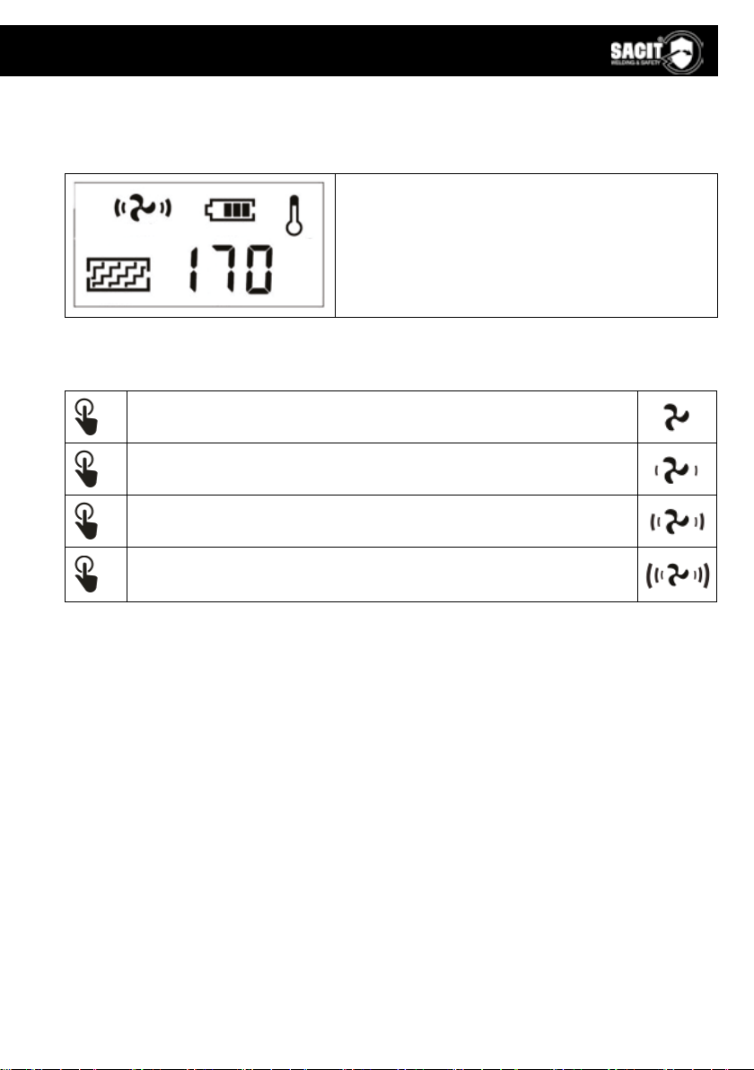
4.1 LCD display screen
There is a LCD display screen on Pantera Air System to show the working system condition.
1.
2. 4. 5.
3.
Part 1 shows the data of current air ow.
Part 2 shows the level of the airow.
Part 3 shows the lter condition.
Part 4 shows the battery.
Part 5 shows the temperature of the battery.
Any of them will ash if there are any disfunctions on Pantera Air System.
4.2 Operation
x1
Switch the device on by pressing the ON button once.
x2
Press the ON button once again, the air ow is at level 1 (~170L/min).
x3
Press the ON button once again, the air ow is at level 2 (~200L/min).
x4
Press the ON button once again, the air ow is at level 3 (~230L/min).
Press the ON button once again, the air ow reverts to level 1 (~170L/min).
1. The system will turn o the turbo unit if long press the OFF button more than 3 seconds.
2. The system will shut down the entire circuit and switch to sleep mode if not used for more
than 30 minutes. Pressing the ON button can activate the system.
3. The system must be operated in the temperature range of -5°C to +55°C and relative
humidity less than 90%RH.

14
EN USER AND MAINTENANCE MANUAL
5. MAINTENANCE & STORAGE
5.1 Maintenance
The Pantera Air System must be checked regularly and must be changed if it is damaged and cause
leakage.
The lter must be changed if it is broken, or it is blocked and does not give enough airow.
The breathing tube must be changed if it is broken or has crevasse.
The battery must be charged when the low battery alarm rings.
Use a soft cloth to wipe the external surfaces. Don’t use water!
The lter should be replaced together with the pre-lter.
5.2 Storage
The Pantera Air System must be stored in a dry, clean area, in the temperature range of -10°C to
+55°C and relative humidity less than 90%RH. If the equipment is stored at temperature below 0°C,
the battery must be allowed to warm up to achieve full battery capacity. The equipment must be
protected from dust, particles and other contamination.
If the equipment is not used for a long time, the battery should be fully charged, removed from
Respiratory system unit and stored separately.
Transport the equipment with original packaging box and away from direct sunlight.
6. SPECIFICATION
Code MSC000441
Norm EN 12941: 1998 +A1:2003+A2:2008 TH3 R SL
Filter type TH3 P R SL
Filter eciency level 99,99% = 0,3 µm
Airow level
1. speed: 170 l/min
2. speed: 200 l/min
3. speed: 230 l/min
Noise level Max 75 dB
Belt size 900 ÷ 1300 mm
Blower unit size 240 x 165 x 70 mm
Blower unit weight 1,1 Kg
Battery model Rechargeable LI-ON 4400 mAh
Battery life
1.speed > 8h
2.speed > 6h
3.speed > 4h
Battery charge time 3,5 h
Number of battery recharges 500
Information on the digital display
Air ow rate and data
Battery level
Filter status
Usage temperature -5°C – +55°C
Storage temperature -10°C – +55°C
15
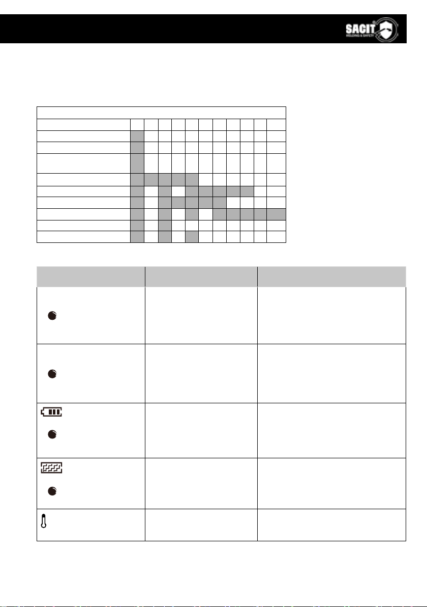
Warning sound indication
Each grid stands for a period of 100ms. Gray is the beep sound and blank grid is a quiet period. If
several continued grids are in gray then there’s a continuous beep sound.
For example, when the current is overloaded, the system sounds like beep~beep~beep~~~~~.
100ms per grid
0 1 2 3 4 5 6 7 8 9 10
Install the battery
Turn on the system
Change the air ow
speed
Turn o the system
Current overload
Air outlet jam
Over heat
Low battery
Filter jam
7. TROUBLE SHOOTING
Problem Probable cause Action
Fault code «E01»
+ warning blinks
1. Motor is stuck
2. Motor is damaged
3. Blower structure failure
caused by outer force
4. Circuit failure
Check and remove physical failure
and restart the system. Return to
dealer if LCD still shows E01
Fault code «E02»
+ warning blinks
1. Motor is damaged
2. Motor impeller rubs blow-
er shell
3. Circuit has excessive
current.
Check and remove physical failure
and restart the system. Return to
dealer if LCD still shows E02
blinks
+ warning blinks
+ alarm sounds
Low battery Charge the battery
blinks
+ warning blinks
+ alarm sounds
Filter blocked
Tube blocked Remove obstruction, change the lter
Clean tube
blinks
+ alarm sounds
Battery high temperature Stop working and rest

16
2797
EN USER AND MAINTENANCE MANUAL
No air ow, no alarm
1. No power
2. Battery contact damaged Charge the battery
Check battery contact
Battery run time is too short
1. Battery is not fully charged
2. Filter is blocked
3. Battery is damaged
Charge the battery
Remove obstruction, change lter
Change battery
Air supply to hood smells
unusual
1. Filter broken
2. Tube broken
3. ADF helmet broken
Leave current area immediately.
1. Change lter
2. Change tube
3. Change ADF helmet
Supply insucient air to
hood
1. Breathing tube broken o
2. Breathing tube broken
3. Filter is blocked
1. Check tube connection to hood and
Respiratory system unit
2. Change breathing tube
3. Remove obstruction, change lter
PANTERA AIR SYSTEM Marking
EN 12941: 1998 +A1:2003+A2:2008
TH3 P R SL
CE1024
Marking explanation:
EN12941:1998 +A1:2003 +A2:2008 = Directive reference
TH3 = Filter model (Protection level)
P = Particle lter / R = Reusable type of particle lters
SL = Tested against particles of liquid and solid.
CE = Conformity mark / 1024 = Certication authority
Notied Body: Vyzkumny ustav bezpecnosti prace, v. v. i., Jeruzalémská 1283/9,
110 00 Praha 1, Czech Republic (Notied body number 1024)
CE mark followed by number of notied body who
carried out module D surveillance.

5
OVERENSSTEMMELSESERKLÆRING
http://shop.tramet.com/it/Dcue-TrametGroup-Adf3.html
Tramet Group Spa, en behørigt registreret italiensk produktionsvirksomhed, beliggende
i Via del Lavoro, 8 36020 Castegnero (VI), erklærer hermed, at produkter identiceret og
beskrevet på disse sider er i overensstemmelse med følgende forordning: EU 2016/425,
samt standarderne EN 175:1997, EN 379:2009, CSA Z94.3, ANSIZ87.1, EN 12941: 1998
+A1:2003+A2:2008 TH3 R SL
ADVARSLER
Læs bruger- og
vedligeholdelsesvejledningen
omhyggeligt før brug.
Ibrugtagning og vedligeholdelse
må kun iværksættes og udføres af
kvaliceret personale. "Kvaliceret
personale" henviser til brugere,
der arbejder i overensstemmelse
med førnævnte bestemmelser og
standarder, og som skal kunne
identicere og vurdere potentielle risici/
farer, der kan opstå under brug af
svejsebrændere.
Produktet skal bortskaes på ansvarlig
vis efter endt levetid. Alle dele og
udstyr skal genbruges korrekt i
overensstemmelse med lokale lovkrav
og forskrifter.
FØR SVEJSNING
Sørg for at fjerne eventuelt
beskyttelsesfolie fra begge sider af
beskyttelsesglasset.
VEDLIGEHOLDELSE
Udskift revnede eller ridsede beskyt-
telsesglas med jævne mellemrum.
ANVENDELSE
Placer aldrig hjelmen eller lteret på et
varmt underlag.
Må kun anvendes i temperaturområdet
-10 °C til +60 °C
SIKKERHEDSFORANSTALTNINGER
Dampe er sundhedsskadelige. Anvend
altid hætte eller udfør arbejde i
ventilerede områder.
Nedsænk ikke det automatiske
nedblændingslter i vand. Udsæt ikke
lteret for væsker og beskyt det mod
snavs.
Foretag ikke modikationer eller
strukturelle ændringer på hjelmen.
Vend brænderen væk fra dig selv og
andre.
Hvis svejselteret ikke bliver mørkt,
når lysbuen antændes, skal du straks
stoppe svejsningen og kontakte din
supervisor eller forhandleren.
Pakkens indhold
PANTERA-maske med automatisk nedblænding
(se g. 1)
KODE BESKRIVELSE
LVE000238 Udvendig beskyt-
telsesplade
114 x 133 x
1 mm
5
LVE000237 Indvendig beskyt-
telsesplade
106 x 66 x 1 mm 5
VCE000010 Ergonomisk hjelm 1
LCD-lter medfølger (se g. 2)
1. Batteridæksel (2 stk.)
2. Batteri (2 stk.)
3. Display
4. WELD/GRIND-knap
5. SENSITIVITY-knap
6. LCD-skærm
7. SHADE-knap
8. DELAY-knap
6
DA BRUGS- OG VEDLIGEHOLDELSESMANUAL
Indledning
Denne manual består af 2 dele:
1. PANTERA-MASKE MED AUTOMATISK NEDBLÆNDING
2. KOMPLET "PANTERA-LUFTSYSTEM"
1. DEL 1 - "PANTERA"-MASKE MED AUTOMATISK NEDBLÆNDING
1.1 Oversigt
PANTERA svejsehjelm med automatisk nedblænding er en ny generation af svejsehjelm, der
integrerer nogle af de mest innovative teknologier såsom digital LCD, optoelektronikdetektion med 4
sensorer og meget bredt visningsområde, solenergi- og litiumbatterier, mikroelektronik og True Color
ADF-teknologi.
PANTERA svejsehjelm med automatisk nedblænding er udstyret med et ADF-lter med digitale
reguleringer, for en nem og hurtig justering af alle funktioner.
Hovedfunktionerne er: MIG/MAG, TIG, PLASMA CUTTING, GOUGING og GRINDING.
Maskens ergonomi er blevet undersøgt for at garantere en fremragende beskyttelse af hoved/nakke/
ører.
ADVARSEL
Læs og forstå alle instruktioner før brug.
• Kontroller, at DIN'en for svejsehjelmlteret har det korrekte nummer til din anvendelse.
• PANTERA-svejsehjelm med automatisk nedblænding og lter er ikke egnet til svejsning i højden,
lasersvejsning eller laserskæring.
• PANTERA-svejsehjelm med automatisk nedblænding er designet til at beskytte øjne og ansigt
mod gnister, svejsesprøjt og skadelig stråling ved anvendelse under normale svejseforhold.
• PANTERA-svejsehjelm med automatisk nedblænding beskytter ikke mod eksplosive anordninger eller
ætsende væsker. Maskinskærme eller øjenbeskyttelse skal anvendes, når disse farer er til stede.
• Slagfast øjenbeskyttelse eller sikkerheds-/beskyttelsesbriller, der opfylder gældende ANSI-
specikationer, skal til enhver tid anvendes ved brug af denne svejsehjelm.
• Undgå arbejdsstillinger, der udsætter ubeskyttede kropsdele for gnister og svejsesprøjt samt
direkte og/eller indirekte stråling. Brug tilstrækkelig beskyttelse, hvis eksponering ikke kan
undgås.
• Før hver brug skal du kontrollere, at beskyttelsespladerne er rene, og at der ikke sidder snavs,
der blokerer for sensorerne foran lteret.
• Inspicer altid betjeningselementerne for tegn på slid eller beskadigelse før brug.
• Eventuelle dele med ridser, revner eller huller skal straks udskiftes.
• Foretag ikke ændringer på hverken svejselteret eller hjelmen ud over dem, der er speciceret i
denne vejledning.
► Brug ikke andre reservedele end dem, der er speciceret i denne manual. Uautoriserede
ændringer og reservedele ugyldiggør garantien og øger risikoen for personskade.
►Hvis beskyttelsesglasset ikke blænder ned, når lysbuen antændes, skal du straks stoppe
svejsningen og kontakte forhandleren.
►Nedsænk ikke dette lter i vand: Denne model er ikke vandtæt.
►Brug ikke opløsningsmidler på lter- eller hjelmkomponenter.
► Det anbefalede driftstemperaturområde for svejselteret er -5 °C til +55 °C. Anvend ikke
denne enhed ud over disse temperaturgrænser.
• Manglende overholdelse af disse advarsler og/eller brugervejledningen kan resultere i alvorlig
personskade.

7
1.2 Egenskaber
PANTERA automatisk svejsehjelm har et automatisk nedblændingslter med 4 sensorer, en digital
skærm og et bredt udsynsområde.
Før aktivering er lterskærmen DIN 4, så brugeren tydeligt kan se arbejdsaden.
Når lysbuen antændes, vil lteret automatisk blænde ned. Når lysbuen aftager, bliver lteret
gennemsigtigt igen. Hjelmen er udstyret med DIN 9-13 nedblændingsregulering. Nedblændingstiden
fra lys til mørk er ca. 0,08 ms og kan indstilles til mellem 0,1–0,9 sekund med DELAY-knappen.
Brugeren kan også justere SENSITIVITY (lysfølsomhed) og vælge driftsmetode (WELD eller GRIND).
PANTERA automatisk svejsehjelm giver brugeren fuld beskyttelse mod UV/IR, selv når lteret er sat
til den svageste indstilling. UV/IR-beskyttelsesniveauet overholder til enhver tid DIN 15. Strømmen
forsynes af solceller og et udskifteligt batteri.
Hjelmen er udstyret med 4 sæt fotosensorer til registrering af lysbue. Desuden er hjelmen forsynet
med en ydre beskyttelsesplade fremstillet af højpolymermaterialer.
Pladen er slidstærk, termostabil, fri for klæbestof og har en meget lang levetid.
1.3 Hovedspecikationer
Filterstørrelse 114 x 133 x 9.5 mm
Udsynsområde 100 x 60 mm
Let skygge DIN-nummer 4
Mørk skygge DIN-nummer 9-13
UV/IR-beskyttelse op til op til DIN 15
Tid fra lys til mørke 0,08 ms
Tid fra mørke til lys 0.1 ... 0,9 s
Følsomhed justerbar trinløs
Strømforsyning solcelle og udskifteligt batteri
Driftstemperatur -5°C (23°F) °F – +55°C (131°F)
Garanti 2 år i henhold til salgsbetingelser
Slibefunktion Ja
Optisk klassikation 1/1/1/1
1.4 Driftsmetode
1. Saml hjelmen som vist på opbygnings- og samlingsillustrationen.
2. Strømforsyningen til PANTERA-hjelmen med automatisk nedblænding forsynes af
solceller med to lithiumbatterier.
3. Valg af nedblændingsgrad Juster til den optimale nedblændingsgrad. Tryk på knappen
SHADE for at vælge mellem nedblændingsgrad 9 og 13. Indstil i henhold til den aktuelle
svejseproces.
4. Valg af tidsforsinkelse Tryk på knappen DELAY for at vælge en forsinkelse på mellem 1
til 5, 0,1–0,9 sekunder.
5. Valg af lysfølsomhed Tryk på knappen SENSITIVITY for at indstille lysfølsomheden over
for det omgivende lys. Vælg mellem fem lysfølsomhedsniveauer.
Indstil til 1: Lysfølsomheden ændres til et lavere niveau. Velegnet til svejsning med høj
strømstyrke og svejsning under skarpe lysforhold (lampelys eller sollys).
Indstil til 5: Lysfølsomheden ændres til et højere niveau. Velegnet til en konstant
lysbueproces såsom TIG-svejsning.

8
DA BRUGS- OG VEDLIGEHOLDELSESMANUAL
6. Fordi hovedform varierer fra person til person. Arbejdspositionen og udsynsvinklen
er forskellige. Brugeren kan justere hovedremmens justeringsknap (15) og
segmentpositioneringspladen (16) for at tilpasse udsynsvinklen.
Juster hovedremmen ved at skubbe og dreje justeringsskruen (11).
7. Slibefunktion Tryk på knappen WELD/GRIND for at vælge slibefunktionen. Slibeblinklyset
vil samtidigt blinke. For at undgå skade på øjnene, må du ikke udføre svejsning i
slibetilstand.
8. Batteriindikator batteriindikatoren er placeret i øverste højre hjørne. Vi foreslår at udskifte
batteriet, når indikatoren blinker.
1.5 Vigtige punkter
1. Sørg for, at hjelmen er i god stand. Kontrollér dens tilstand i henhold til ADVARSEL-
meddelelser.
2. Der sidder en ventil med ydende krystaller i lteret. Selv om den har en indre og ydre
beskyttelsesplade, er det vigtigt at undgå kraftige stød, så den forbliver intakt.
3. Hjelmens ydre beskyttelsesplade skal efterses og rengøres med jævne mellemrum.
Sørg for, at der er frit udsyn. Hvis der opstår brud, revner, huller eller mere alvorlig
synspåvirkning, skal pladen udskiftes.
4. For bedre eektivitet og sikkerhed skal du vælge en korrekt mørk nuance.
5. Hvis lteret ikke er en vandtæt model, skal du beskytte det mod våde miljøer.
6. Sørg for, at lys fra lysbuen opfanges af sensoren. Hvis ikke, vil lteret være for lyst eller
ustabilt i mørke, hvilket kan forårsage personskade.
7. Det automatiske lter kan anvendes i en temperatur fra -10 °C til +55 °C.
8. Adskil ikke lteret. Hvis der opstår problemer, bedes du kontakte os eller agent.
1.6 Mærkning
4 Tydeligt DIN sikkerhedsniveau
9-13 Skygge DIN-sikkerhedsniveau
SA Producent
1 Optisk klasse
1 Lysdiuserende klasse
1 Variationer i lysgennemtrængelighedsklasse
1 Vinkelafhængighedsklasse
EN379 CE Direktivhenvisning og overensstemmelsesmærke
Table of contents
Languages:
Other Trafimet Welding Accessories manuals


Popular Welding Accessories manuals by other brands


Smith
Smith Little Torch owner's manual

Lincoln Electric
Lincoln Electric AutoDrive 19 TANDEM Operator's manual

Miller Electric
Miller Electric S-75D owner's manual

ESAB
ESAB Aristo U6 instruction manual

Abicor Binzel
Abicor Binzel FES-200 operating instructions

3M
3M Speedglas 9100 FX Series Care & maintenance


