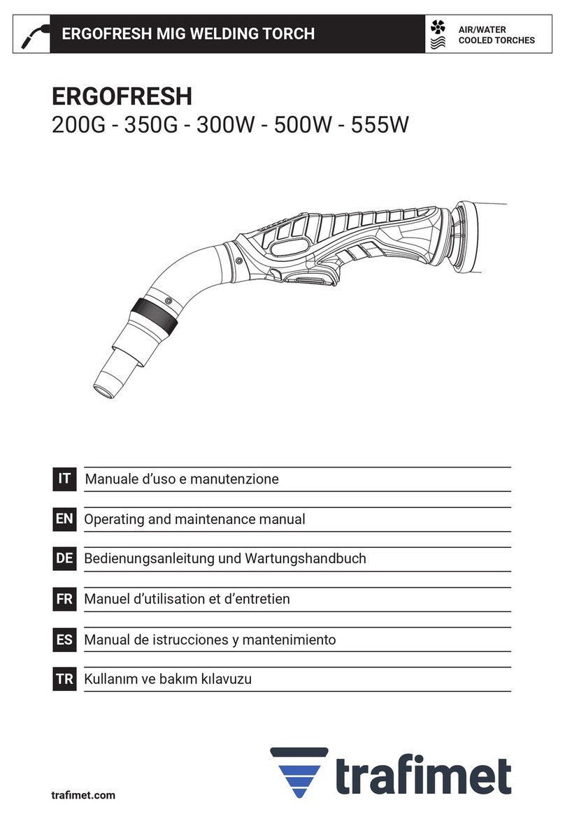
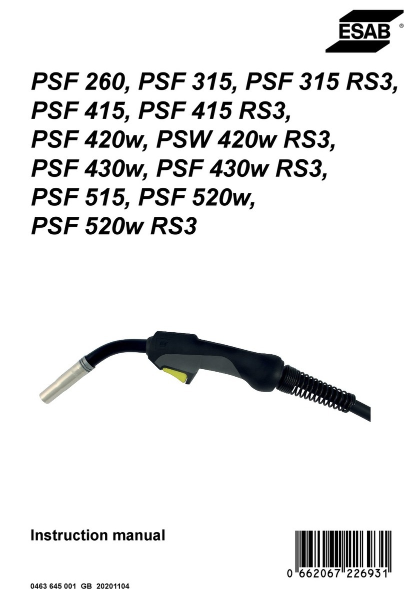
Trafimet ERGOFRESH 200G Operating instructions

trafimet.com
IT
EN
DE
FR
ES
TR
Manuale d’uso e manutenzione
Operating and maintenance manual
Bedienungsanleitung und Wartungshandbuch
Manuel d’utilisation et d’entretien
Manual de istrucciones y mantenimiento
Kullanım ve bakım kılavuzu
ERGOFRESH
200G - 350G - 300W - 500W
AIR/WATER
COOLED TORCHES
MIG WELDING (GMAW) TORCHES

±°C
EN 60974-7
Tutti i marchi sono di proprietà dei rispettivi proprietari. Le informazioni e le immagini sono indicative e possono essere soggette a modiche in qualunque momento senza preavviso. © 2022 Tramet Group SpA
IT MANUALE D'USO E MANUTENZIONE
DICHIARAZIONE DI CONFORMITÀ
DICHIARAZIONE DI CONFORMITÀ
Trafimet Group Spa, azienda manifatturiera italiana regolarmente registrata, con sede in Via del Lavoro 8,
36020 Castegnero (VI), dichiara che i prodotti identificati e descritti nel presente manuale sono conformi
a quanto previsto dalla Direttiva 2014/35 UE sulle basse tensioni e agli standard stabiliti dalla EN 60974-7
Attrezzatura per la saldatura ad arco - Parte 7.
Trafimet Group Spa, azienda manifatturiera italiana regolarmente registrata, con sede in Via del Lavoro 8,
36020 Castegnero (VI), dichiara che i prodotti identificati e descritti nel presente manuale sono conformi
aquanto previsto dalle Normative del 2016 sulle apparecchiature elettriche (sicurezza) e dalle Normative
del2012 sull'uso di determinate sostanze pericolose nelle apparecchiature elettriche ed elettroniche.
IDENTIFICAZIONE DEL PROCESSO
Le torce di saldatura MIG/MAG manuali ERGOFRESH sono progettate per saldare materiali scarsamente o altamente legati.
Le torce di saldatura ERGOFRESH catturano i fumi di saldatura in corrispondenza dell’arco, pulendo la zona di respirazione
del saldatore. La gamma ERGOFRESH copre sia i modelli raffreddati ad acqua sia quelli raffreddati a gas perla saldatura
MIG. Le torce per l’estrazione dei fumi vengono utilizzate insieme a un’unità di estrazione fumi. Le torce disaldatura ERGO-
FRESH sono compatibili con le unità di estrazione fumi della maggior parte dei principali produttori.
Per ulteriori informazioni, fare riferimento alla documentazione del produttore sull’unità di estrazione fumi.
AVVERTENZE
PRECAUZIONI DI SICUREZZA
Indossare guanti e altri
indumenti da lavoro
adeguati in conformità
allenormative locali.
I fumi sono pericolosi per
la salute. Usare sistemi per
l'aspirazione dei fumi oppure
eseguire saldature esclusiva-
mente in ambienti ventilati.
Proteggere gli utensili
elettrici dalla pioggia. Non
utilizzare la torcia di salda-
tura su superfici o pavimenti
bagnati oppure in ambienti
con un'umidità elevata.
I cavi della torcia non
devono essere schiacciati
da oggetti pesanti.
Rivolgere la torcia lontano
da sa stessi e dagli altri.
L'arco è pericoloso per gli
occhi. Indossare un casco
protettivo. Le persone nelle
vicinanze devono indossare
una protezione per gli occhi.
Non eseguire
saldature in siti
inammabili
o esplosivi.
Non eseguire saldature
su superfici verniciate.
Non modificare la torca
né apportare modifiche
strutturali ad essa.
Prima di utilizzare le torce,
è necessario leggere
attentamente il manuale
d'uso e manutenzione.
Condizioni ambientali
Funzionamento:
Da -10 °C a +40 °C (da +14 °F a +104 °F)
Trasporto e stoccaggio:
Da -25 °C a +55 °C (da -13 °F a +131 °F)
Umidità relativa:
Fino al 90% a 20 °C (68 °F)
Spegnere la fonte di
alimentazione prima di
eseguire la manutenzione
della torcia. La sostituzione
delle parti di ricambio
oattività di manutenzione
di altro tipo devono
essere effettuate dopo il
raffreddamento della torcia.
Smaltire questo prodotto
in modo responsabile
dopo l'uso. Le torce e le
parti usate devono essere
adeguatamente riciclate in
conformità ai requisiti/alle
normative locali.

Tutti i marchi sono di proprietà dei rispettivi proprietari. Le informazioni e le immagini sono indicative e possono essere soggette a modiche in qualunque momento senza preavviso. © 2022 Tramet Group SpA
COLLEGAMENTI
UTILIZZO
MANUTENZIONE
Prima di collegare la
torcia, spegnere la fonte
di alimentazione, staccare
la spina e chiudere la
fornitura di gas.
Prima di collegare
la torcia alla fonte
di alimentazione,
vericare che i
collegamenti elettrici
siano corretti e in
conformità agli schemi
elettrici allegati,
laddove applicabile.
Accertarsi che la guaina
in filo metallico e la punta
di contatto corrispondano
al diametro del filo di
riempimento.
Non piegare i cavi e i tubi
flessibili per evitare danni
che potrebbero impedire
la corretta circolazione
del gas e del refrigerante.
Non usare la torcia
per scopi diversi dalla
saldatura.
Spegnere la fonte
di alimentazione
prima di eseguire la
manutenzione della
torcia. La sostituzione
delle parti di ricambio o
attività di manutenzione
di altro tipo devono
essere eettuate dopo
il rareddamento
della torcia.
Se la punta di contatto
èusurata o danneggiata,
sostituirla.
Sostituire la guaina in
filo metallico se ci sono
problemi con il trainafilo.
Controllare
periodicamente le
condizioni del cavo e del
manico. Le riparazioni
possono essere eseguite
solo da personale
qualificato.
Usare sempre parti di
ricambio e materiali
di consumo originali
Trafimet.
Pulire periodicamente
l'ugello del gas eil
diffusore di gas.
Utilizzare uno spray
antiadesivo.
Con l’estrazione dei fumi attiva,
i fumi caldi passano attraverso
l’impugnatura della torcia e
influiscono sulla temperatura
dell’impugnatura.

Tutti i marchi sono di proprietà dei rispettivi proprietari. Le informazioni e le immagini sono indicative e possono essere soggette a modiche in qualunque momento senza preavviso. © 2022 Tramet Group SpA
IT MANUALE D'USO E MANUTENZIONE
FUNZIONAMENTO
Informazioni importanti su come utilizzare la torcia di saldatura MIG in modo sicuro. Classificazione dei
comandi elettrici della torcia: 32 V DC 0,05 A.
Alimentazione dell’unità di raffreddamento per torce raffreddate ad acqua: almeno 800 W.
Prima di usare la torcia, accertarsi che tutti i cavi siano in buone condizioni e che i connettori siano fissati
correttamente.
Come collegare la torcia
Collegare la torcia alle attrezzature di saldatura.
Fissare il connettore ruotando il collare in senso
orario.
Collegare il tubo flessibile dell’aspiratore della torcia al tubo flessibile collegato all’unità di estrazione fumi.
Se necessario, assicurare il collegamento con il nastro della torcia.
Collegare i tubi flessibili di ingresso e uscita del
refrigerante all'attrezzatura di saldatura. Si noti che
iconnettori seguono una codifica a colori.

1 - 2 mm
1
2
3
4
5
Tutti i marchi sono di proprietà dei rispettivi proprietari. Le informazioni e le immagini sono indicative e possono essere soggette a modiche in qualunque momento senza preavviso. © 2022 Tramet Group SpA
FUNZIONAMENTO
Come installare e sostituire la guaina in filo metallico
Le torce di saldatura MIG ERGOFRESH vengono fornite con la guaina in filo metallico preinstallata. Consultare questa
sezione quando è necessario sostituire la guaina guidafilo. La guaina guidafilo è un materiale di consumo che deve
essere cambiato in caso di usura o quando si cambia il materiale del filo.
Se si cambia il filo di apporto con un filo di diametro o materiale diverso, è necessario cambiare anche i rulli
di alimentazione nel sistema trainafilo.
Prima di sostituire la guaina guidafilo, è necessario rimuovere il filo di apporto.
Raddrizzare il cavo della torcia di saldatura erimuovere il dado della guaina.
Rimuovere l’ugello del gas e la punta di contatto. Se la guaina in filo metallico non passa attraverso il
supporto della punta, rimuovere anche il supporto della punta.
Tagliare la guaina in filo metallico lasciando
1-2 mm di guaina in eccesso.
Rimuovere i bordi ruvidi che potrebbero danneggiare il filo di apporto.
Riavvitare il dado della guaina in posizione eserrarlo con uno strumento.

1
2
3
Tutti i marchi sono di proprietà dei rispettivi proprietari. Le informazioni e le immagini sono indicative e possono essere soggette a modiche in qualunque momento senza preavviso. © 2022 Tramet Group SpA
IT MANUALE D'USO E MANUTENZIONE
Come installare e rimuovere l’impugnatura
Mantenendo la parte inferiore dell’impugnatura rivolta in avanti, inserire le relative scanalature
sopra l’impugnatura della torcia.
Tirare l’impugnatura all’indietro per bloccarla inposizione.
Per rimuovere l’impugnatura, premere il pulsante di blocco situato nella parte posteriore dell’impugnatura.
FUNZIONAMENTO

1
1
2
2 3
Tutti i marchi sono di proprietà dei rispettivi proprietari. Le informazioni e le immagini sono indicative e possono essere soggette a modiche in qualunque momento senza preavviso. © 2022 Tramet Group SpA
FUNZIONAMENTO
Sostituzione dell'ugello dell'aspiratore e della molla di bloccaggio
L'ugello dell'aspiratore e la molla di bloccaggio sono parti consumabili che, se usurate, devono essere sostituite.
Sostituzione dell'ugello di saldatura
L'ugello è un materiale di consumo che, se usurato, deve essere sostituito.
Svitare e rimuovere il vecchio ugello
dell'aspiratore.
Allentare l'ugello
dell'aspiratore
erimuoverlo.
Se necessario, sostituire la molla di bloccaggio.
Inserire il nuovo ugello e avvitarlo in posizione.
Inserire il nuovo
ugello.
Stringere l'ugello
dell'aspiratore e bloccare
in posizione il nuovo
ugello con la punta della
torcia rivolta verso l'alto
per un bloccaggio più
semplice.

1
2
3
Tutti i marchi sono di proprietà dei rispettivi proprietari. Le informazioni e le immagini sono indicative e possono essere soggette a modiche in qualunque momento senza preavviso. © 2022 Tramet Group SpA
IT MANUALE D'USO E MANUTENZIONE
FUNZIONAMENTO
IT MANUALE D'USO E MANUTENZIONE
Sostituzione del coperchio del tubo flessibile dell'aspiratore
Il tubo flessibile della torcia di saldatura ERGOFRESH è dotato di una copertura in pelle fissata con fascette.
La copertura in pelle del tubo flessibile dell'aspiratore è un materiale di consumo che, se usurato, deve essere sostituito.
Flusso d'aria per l'estrazione dei fumi
Le torce per l'estrazione dei fumi devono fornire la quantità adeguata di gas di protezione per evitare che la saldatura
presenti difetti senza compromettere l'efficienza di cattura dei fumi della torcia. Se il flusso d'aria per l'estrazione dei fumi
è troppo forte, cattura il gas di protezione. Se il flusso d'aria per l'estrazione dei fumi è troppo debole, non cattura i fumi di
saldatura in modo sufficientemente efficace.
Diminuzione del flusso d'aria per l'estrazione dei fumi
Per diminuire il flusso d'aria per l'estrazione dei fumi, utilizzare il coperchio bypass del flusso d'aria sull'impugnatura
della torcia.
Rimuovere la vecchia copertura in pelle.
Avvolgere la nuova copertura in pelle attorno al tubo flessibile
dell'aspiratore.
Bloccare la chiusura a strappo e le due fascette per cavi
alle estremità.
Per la regolazione del flusso d'aria per l'estrazione fumi sull'unità di estrazione fumi, fare riferimento
ai manuali operativi del produttore dell'unità di estrazione fumi.

Tutti i marchi sono di proprietà dei rispettivi proprietari. Le informazioni e le immagini sono indicative e possono essere soggette a modiche in qualunque momento senza preavviso. © 2022 Tramet Group SpA
FUNZIONAMENTO
Ottimizzazione dell'efficienza dell'estrazione dei fumi
I seguenti fattori aiutano a massimizzare l'efficienza dell'estrazione dei fumi di una torcia per saldatura ERGOFRESH.
Le seguenti figure mostrano in che modo i tipi di giunti influiscono
sull'efficienza di cattura dei fumi.
L'ottimizzazione migliore è mostrata a sinistra.
Posizioni di saldatura e tipi di giunti
La posizione più efficace per l'estrazione
dei fumi è la posizione piatta perché i fumi
salgono naturalmente verso l'alto.
0...15°
0...15°
Materiale del filo e angolo della torcia
Se si utilizzano fili animati, saldare con un
angolo di trazione della torcia di 0...15°.
Eliminazione dei fumi residui
Al termine della saldatura, tenere in posizione la torcia per l'estrazione fumi per 10... 15 secondi. In
questo modo, la torcia riesce a eliminare i fumi residui durante il raffreddamento della saldatura.
Se si utilizzano fili pieni, saldare con un
angolo di spinta della torcia di 0...15°.

±°C
EN 60974-7
All trademarks are the property of their respective owners. The information and images are indicative and may be subject to change at any time without notice. © 2022 Tramet Group SpA
EN OPERATING AND MAINTENANCE MANUAL
DECLARATION OF CONFORMITY
DECLARATION OF CONFORMITY
Trafimet Group Spa, a duly registered Italian Manufacturing Company, located in Via del Lavoro, 8 36020
Castegnero (VI), hereby declares that products identified and described in this manual are in conformity with
the provisions of Low Voltage Directive 2014/35 EU and in compliance with the standards set by EN 60974-7
Arc Welding Equipment - Part 7.
Trafimet Group Spa, a duly registered Italian Manufacturing Company, located in Via del Lavoro, 8 36020
Castegnero (VI), hereby declares that the products identified and described in this manual comply with the
provisions of the Electrical Equipment (Safety) Regulations 2016 and the Restriction of the Use of Certain
Hazardous Substances in Electrical and Electronic Equipment Regulations 2012.
PROCESS IDENTIFICATION
ERGOFRESH manual MIG/MAG welding torches are designed for welding low- and high-alloyed materials. ERGOFRESH
welding torches capture welding fumes at the arc, cleaning the welder’s breathing zone. ERGOFRESH range covers both
water-cooled and gas-cooled models for MIG welding. Fume extraction torches are used in conjunction with a fume
extraction unit. ERGOFRESH welding torches are compatible with fume extraction units of most major manufacturers.
For more information, refer to the fume extraction unit manufacturer’s documentation.
WARNINGS
SAFETY PRECAUTIONS
Wear gloves and other
suitable workwear in
accordance with local
regulations.
Fumes are hazardous to
health. Use fume extraction
systems or weld in
ventilated spaces only.
Protect power tools from
rain. Do not use the welding
torch on wet surfaces/
floors or in spaces with high
humidity.
Torch cables must not
be squashed by heavy
objects.
Point the torch away from
yourself and others.
Arc is dangerous to the
eyes. Wear a protective
helmet. Nearby people
should wear eye
protection.
Do not weld in
ammable or explosive
sites.
Do not weld on painted
surfaces.
Do not modify or make
structural changes to the
torch.
Please read carefully the
operating and maintenance
manual before use.
Ambient conditions
Operation:
-10°C to +40°C (+14°F to +104°F)
Transport and storage:
-25°C to +55°C (-13°F to +131°F)
Relative humidity:
Up to 90 % at 20°C (68°F)
Turn off the power source
before performing torch
maintenance. Replacement
of spare parts or other
maintenance must be
performed after the torch
has cooled down.
Dispose of this product
responsibly after use.
Torches and used parts
should be properly
recycled according to
the local requirements/
regulations.

All trademarks are the property of their respective owners. The information and images are indicative and may be subject to change at any time without notice. © 2022 Tramet Group SpA
CONNECTIONS
Before connecting the
torch, switch off the
power source, disconnect
the power plug and
switch off the gas supply.
Before connecting
the torch to the
power source,
check the correct
electrical connections
according to the
enclosed wiring
diagrams, where
applicable.
Make sure that the wire
liner and contact tip
match the diameter of
the filler wire.
With fume extraction
on, hot fumes pass
through the torch handle
and affect the handle’s
temperature.
Do not bend cables and
hoses in order to avoid
damages that may prevent
proper gas and coolant
circulation.
Do not use the torch
for purposes other than
welding.
Turn off the power
source before perfoming
torch maintenance.
Replacement of any
spare parts or other
maintenance must be
performed after the
torch has cooled down.
Replace the contact tip if
it is worn or damaged.
Replace the wire liner if
there are problems with
the wire feed.
Check the condition of
the cable and handle
periodically. Repairs
may be carried out by
qualified personnel only.
Always use the original
Trafimet spare parts and
consumables.
Clean the gas nozzle and
gas diffuser periodically.
Use anti-adhesive spray.
MAINTENANCE
USE

All trademarks are the property of their respective owners. The information and images are indicative and may be subject to change at any time without notice. © 2022 Tramet Group SpA
EN OPERATING AND MAINTENANCE MANUAL
OPERATION
Important information on the safe use of the MIG welding torch. Rating of electrical controls incorporated in
the torch: 32VDC 0.05A.
Cooling unit power for water-cooled torches: Minimum 800W.
Before using the torch, ensure that all the cables are in serviceable condition and that the connectors are
correctly fastened.
How to connect the torch
Connect the torch to your welding equipment.
Secure the connector in place by turning the collar
clockwise.
Connect the coolant inlet and outlet hoses to your
welding equipment.
Note that the connectors are color-coded.
Connect the gun’s vacuum hose to the hose connected to the fume extraction unit. If necessary, secure the
connection with torch’s tape.

1 - 2 mm
1
2
3
4
5
All trademarks are the property of their respective owners. The information and images are indicative and may be subject to change at any time without notice. © 2022 Tramet Group SpA
OPERATION
How to install and replace wire liner
ERGOFRESH MIG welding torches are delivered with the wire liner preinstalled.
Refer to this section when the wire liner needs to be replaced.
The wire liner is a consumable part, which needs to be changed if worn and when the filler wire material changes.
If you change the filler wire to a different diameter or material, change also the feed rolls in the wire feed
system accordingly.
The filler wire must be removed before the wire liner replacement.
Straighten the welding torch cable and remove the liner nut.
Remove the gas nozzle and the contact tip. If the wire liner does not pass through the tip holder, remove
the tip holder as well.
Cut the wire liner leaving 1-2 mm of excess liner.
Remove any rough edges that could potentially damage the filler wire.
Screw the liner nut back in place and tighten it with a tool.

1
2
3
All trademarks are the property of their respective owners. The information and images are indicative and may be subject to change at any time without notice. © 2022 Tramet Group SpA
EN OPERATING AND MAINTENANCE MANUAL
How to install and remove grip handle
OPERATION
Keeping the bottom of the grip handle pointing forward, fit the grooves of the grip handle over on
the torch handle.
Pull the handle backward to lock it in position.
To remove the grip handle, press the lock button in the grip handle rear.

1
1
2
2 3
All trademarks are the property of their respective owners. The information and images are indicative and may be subject to change at any time without notice. © 2022 Tramet Group SpA
Replacing vacuum nozzle and lock spring
The vacuum nozzle and the lock spring are consumable parts, which need to be changed if worn.
Replacing welding nozzle
The welding nozzle is a consumable part, which needs to be changed if worn.
OPERATION
Unscrew and remove the old vacuum nozzle.
Loosen the vacuum
nozzle and remove the
old welding nozzle.
Change the lock spring if necessary.
Insert the new vacuum nozzle and screw it in
place.
Insert the new welding
nozzle.
Tighten the vacuum
nozzle and lock the
new welding nozzle in
place with the tip of the
torch pointing up for
easier locking.

1
2
3
All trademarks are the property of their respective owners. The information and images are indicative and may be subject to change at any time without notice. © 2022 Tramet Group SpA
EN OPERATING AND MAINTENANCE MANUAL
OPERATION
Replacing vacuum hose cover
ERGOFRESH welding torch’s vacuum hose comes with a leather cover, attached with cable ties.
The vacuum hose leather cover is a consumable part, which needs to be changed if worn.
Fume extraction air flow
Fume extraction torches need to provide the appropriate amount of shielding gas to protect the weld from defects
without compromising the fume capture efficiency of the torch. If the fume extraction air flow is too strong, it captures
shielding gas. If the fume extraction air flow is too weak, it doesn’t capture welding fumes effectively enough.
Decreasing fume extraction air flow
To decrease the fume extraction air flow, use the air flow bypass lid on the torch handle.
Remove the old leather cover.
Wrap the new leather cover around the vacuum hose.
Close the hook-and-loop fastener and
the two cable ties on the ends.
For adjusting the fume extraction air flow at the fume extraction unit, refer to the operating manuals of the
fume extraction unit manufacturer.

0...15°
0...15°
All trademarks are the property of their respective owners. The information and images are indicative and may be subject to change at any time without notice. © 2022 Tramet Group SpA
OPERATION
Optimizing fume extraction efficiency
The following factors help maximizing the fume extraction efficiency of a ERGOFRESH welding gun.
The following figures display how joint types affect fume capture efficiency.
The best optimization is shown on the left.
Welding positions and joint types
The most effective position for fume
extraction is the flat position because the
fumes naturally rise upward.
Wire material and gun angle
When welding with flux-cored wires, weld
with a 0 ... 15° pulling torch angle.
Removal of residual fumes
At the end of welding, hold the fume extraction torch in place for 10 ... 15 seconds. This allows the
torch to remove residual fumes as the weld is cooling.
When welding with solid wires, weld with
a 0 ... 15° pushing torch angle.

±°C
EN 60974-7
Alle Markenzeichen sind ausschließliches Eigentum der jeweiligen Firmen. Daten und Bilder sind Richtwerte und können jederzeit ohne Vorankündigung geändert werden. © 2022 Tramet Group SpA
DE BEDIENUNGSANLEITUNG UND WARTUNGSHANDBUCH
KONFORMITÄTSERKLÄRUNG
KONFORMITÄTSERKLÄRUNG
Trafimet Group Spa, ein ordnungsgemäß eingetragenes italienisches Produktionsunternehmen mit Sitz in
der Via del Lavoro, 8 36020 Castegnero (VI), erklärt hiermit, dass die in diesem Handbuch bezeichneten und
beschriebenen Produkte den Bestimmungen der Niederspannungsrichtlinie 2014/35 EU und den von der EN
60974-7 Lichtbogenschweißeinrichtungen – Teil 7 festgelegten Normen entsprechen.
Trafimet Group Spa, ein ordnungsgemäß eingetragenes italienisches Produktionsunternehmen mit Sitz in
der Via del Lavoro, 8 36020 Castegnero (VI), erklärt hiermit, dass die in diesem Handbuch bezeichneten und
beschriebenen Produkte den Bestimmungen im Hinblick auf die Sicherheit von Elektrogeräten aus dem Jahr
2016 und der Beschränkung der Verwendung bestimmter Gefahrenstoffe in Elektro- und Elektronikgeräten
aus dem Jahr 2012 entsprechen.
PROZESSBESTIMMUNG
Die ERGOFRESH MIG/MAG-Handschweißbrenner sind für das Schweißen von niedrig- und hochlegierten Werkstoffen
konzipiert. ERGOFRESH Schweißbrenner saugen den Schweißrauch am Lichtbogen ab und reinigen so die Atemzone
des Schweißers. Das ERGOFRESH-Sortiment umfasst sowohl wassergekühlte als auch gasgekühlte Modelle für das
MIG-Schweißen. Rauchgasabsaugbrenner werden in Verbindung mit einer Rauchabsaugeinheit verwendet. ERGOFRESH-
Schweißbrenner sind mit den Rauchabsaugeinheiten der meisten großen Hersteller kompatibel.
Weitere Informationen finden Sie in der Dokumentation des Herstellers der Rauchabsaugeinheit.
WARNHINWEISE
SICHERHEITSHINWEISE
Tragen Sie Handschuhe
und weitere geeignete
Arbeitskleidung gemäß den
örtlichen Vorschriften.
Dämpfe sind
gesundheitsschädlich.
Rauchabsauganlagen
verwenden oder nur in gut
belüfteten Räumen schweißen.
Elektrowerkzeuge vor
Regen schützen. Den
Schweißbrenner nicht auf
nassen Oberflächen/Böden
oder in Räumen mit hoher
Luftfeuchtigkeit verwenden.
Brennerkabel dürfen
nicht von schweren
Gegenständen
gequetscht werden.
Brenner immer von sich
selbst und anderen
entfernt halten.
Der Lichtbogen ist gefährlich
für die Augen. Tragen Sie
einen Helm. In der Nähe
befindliche Personen sollten
einen Augenschutz tragen.
Nicht an
entammbaren
oder explosiven
Orten schweißen.
Nicht auf lackierten
Oberflächen schweißen.
Keine baulichen
Veränderungen am
Brenner vornehmen.
Bitte lesen Sie die
Bedienungs- und
Wartungsanleitung vor dem
Gebrauch sorgfältig durch.
Umgebungsbedingungen
Betrieb:
–10°C bis +40°C
Transport und Lagerung:
–25°C bis +55°C
Relative Luftfeuchtigkeit:
Bis zu 90% bei 20°C
Schalten Sie die Stromquelle
vor der Durchführung von
Wartungsarbeiten am Brenner
aus. Der Austausch von
Ersatzteilen oder andere
Wartungsarbeiten dürfen
erst durchgeführt werden,
nachdem sich der Brenner
abgekühlt hat.
Entsorgen Sie das
Produkt nach Gebrauch
verantwortungsbewusst.
Brenner und gebrauchte
Teile sind immer
ordnungsgemäß
(gemäß den geltenden
lokalen Anforderungen/
Vorschriften) zu recyceln.

Alle Markenzeichen sind ausschließliches Eigentum der jeweiligen Firmen. Daten und Bilder sind Richtwerte und können jederzeit ohne Vorankündigung geändert werden. © 2022 Tramet Group SpA
ANSCHLÜSSE
VERWENDUNG
WARTUNG
Schalten Sie vor dem
Anschließen des
Brenners die Stromquelle
aus, ziehen Sie den
Netzstecker und schalten
Sie die Gaszufuhr ab.
Vor dem Anschließen
des Brenners an
die Stromquelle
prüfen Sie ggf. die
korrekten elektrischen
Anschlüsse gemäß
den beiliegenden
Schaltplänen.
Achten Sie darauf,
dass der Drahtleiter
und die Stromdüse
dem Durchmesser des
Fülldrahts entsprechen.
Knicken Sie die Kabel
und Schläuche nicht
ab, um Schäden zu
vermeiden, die eine
ordnungsgemäße Gas-
und Kühlmittelzirkulation
verhindern können.
Verwenden Sie den
Brenner nicht für
andere Zwecke als
zum Schweißen.
Schalten Sie vor der
Durchführung von
Wartungsarbeiten am
Brenner die Stromquelle
aus. Der Austausch von
Ersatzteilen oder andere
Wartungsarbeiten dürfen
erst durchgeführt werden,
nachdem sich der Brenner
abgekühlt hat.
Ersetzen Sie die
Stromdüse, wenn
sie abgenutzt oder
beschädigt ist.
Ersetzen Sie den
Drahtleiter bei
Problemen mit dem
Drahtvorschub.
Überprüfen Sie
regelmäßig den Zustand
des Kabels und der
Zuleitung. Reparaturen
dürfen nur von
qualifiziertem Personal
durchgeführt werden.
Verwenden Sie immer
Original-Ersatzteile und
-Verschleißteile von
Trafimet.
Reinigen Sie die Gasdüse
und den Gasverteiler
regelmäßig. Verwenden
Sie Antihaftspray.
Bei eingeschalteter
Absaugung strömen
heiße Dämpfe durch den
Brennergriff und beeinflussen
die Temperatur des Griffs.

Alle Markenzeichen sind ausschließliches Eigentum der jeweiligen Firmen. Daten und Bilder sind Richtwerte und können jederzeit ohne Vorankündigung geändert werden. © 2022 Tramet Group SpA
DE BEDIENUNGSANLEITUNG UND WARTUNGSHANDBUCH
BETRIEB
Wichtige Informationen zum sicheren Umgang mit dem MIG-Schweißbrenner. Nennwerte der im Brenner
integrierten elektrischen Steuerungen: 32V DC, 0,05A
Leistung der Kühleinheit für wassergekühlte Brenner: Min. 800W
Vergewissern Sie sich vor der Verwendung des Brenners, dass alle Kabel in betriebsbereitem Zustand und
die Anschlüsse ordnungsgemäß befestigt sind.
So schließen Sie den Brenner an
Schließen Sie den Brenner an Ihr Schweißgerät
an. Sichern Sie den Anschluss durch Drehen des
Ringes im Uhrzeigersinn.
Verbinden Sie den Absaugschlauch des Schweissbrenners mit dem Schlauch, der an die Rauchabsaugeinheit
angeschlossen ist. Sichern Sie die Verbindung gegebenenfalls mit Band am Brenner.
Verbinden Sie den Ein- und Ausgangsschlauch für
das Kühlmittel mit Ihrer Schweißmaschine. Beachten
Sie, dass die Anschlüsse farbcodiert sind.
Other manuals for ERGOFRESH 200G
1
This manual suits for next models
3
Table of contents
Languages:
Other Trafimet Welding Accessories manuals

