Trafimet ERGOFRESH 200G Operating instructions

tramet.com
ERGOFRESH
200G - 350G - 300W - 500W - 555W
IT
EN
DE
FR
ES
TR
Manuale d’uso e manutenzione
Bedienungsanleitung und Wartungshandbuch
Manuel d’utilisation et d’entretien
Manual de istrucciones y mantenimiento
Kullanım ve bakım kılavuzu
Operating and maintenance manual
AIR/WATER
COOLED TORCHES
ERGOFRESH MIG WELDING TORCH
2
EN 60974-7
ISO 21904-3
ISO 21904-1
1
2
2
3
3
1
4
4
5
5
200G/350G/300W
500W/555W
Tutti i marchi sono di proprietà dei rispettivi proprietari. Le informazioni e le immagini sono indicative e possono essere soggette a modiche
in qualunque momento senza preavviso. ©2023 Tramet Group SpA
IT TORCIA DI SALDATURA MIG ERGOFRESH
DICHIARAZIONE DI CONFORMITÀ
Tramet Group Spa, azienda manifatturiera italiana regolarmente registrata, con sede in Via del Lavoro 8, 36020 Castegnero
(VI), dichiara che i prodotti identicati e descritti nel presente manuale sono conformi a quanto previsto dalla Direttiva
2014/35UE sulle basse tensioni e agli standard stabiliti dalla EN 60974-7 Attrezzatura per la saldatura ad arco - Parte 7.
Tramet Group Spa, azienda manifatturiera italiana regolarmente registrata, con sede in Via del Lavoro 8, 36020 Castegnero
(VI), dichiara che i prodotti identicati e descritti nel presente manuale sono conformi a quanto previsto dalle Normative del
2016 sulle apparecchiature elettriche (sicurezza) e dalle Normative del 2012 sull'uso di determinate sostanze pericolose nelle
apparecchiature elettriche ed elettroniche.
NOTE IMPORTANTI
Usare sempre parti di ricambio e materiali di consumo originali Tramet.
Leggere attentamente tutte le istruzioni. Per garantire la sicurezza propria e dell'ambiente di lavoro, prestare particolare attenzione
alle istruzioni per la sicurezza fornite con l'attrezzatura.
Smaltire questo prodotto in modo responsabile dopo l'uso. Le torce e le parti usate devono essere adeguatamente riciclate
in conformità ai requisiti e alle normative locali.
Prima di maneggiare i cavi elettrici o di eseguire la manutenzione della torcia, scollegare la fonte di alimentazione
dall'alimentazione di rete.
Prima di collegare la torcia, spegnere la fonte di alimentazione, staccare la spina e disattivare la fornitura di gas.
I punti del manuale che richiedono una particolare attenzione per ridurre al minimo eventuali danni materiali e lesioni personali sono
segnalati dai simboli descritti in basso. Leggere attentamente queste sezioni e osservarne le istruzioni.
Nota: fornisce informazioni utili.
Attenzione: descrive una situazione che potrebbe comportare danni all'attrezzatura o al sistema.
Avviso: descrive una situazione potenzialmente pericolosa. Se non evitata, comporta danni personali o lesioni mortali.
INFORMAZIONI SULL'ATTREZZATURA
Le torce di saldatura MIG/MAG manuali ERGOFRESH sono progettate per saldare materiali scarsamente o altamente legati. Le torce di
saldatura ERGOFRESH catturano i fumi di saldatura in corrispondenza dell'arco, pulendo la zona di respirazione del saldatore. La gamma
ERGOFRESH copre sia i modelli raffreddati ad acqua sia quelli raffreddati a gas per la saldatura MIG. Le torce per l'estrazione dei fumi
vengono utilizzate insieme a un'unità di estrazione fumi. Le torce di saldatura ERGOFRESH sono compatibili con le unità di estrazione
fumi della maggior parte dei principali produttori. Per ulteriori informazioni, fare riferimento alla documentazione del produttore sull'unità
di estrazione fumi.
L'attrezzatura è composta da (i dettagli visivi esatti possono differire tra i diversi modelli di torce):
1) Diffusore di gas
2) Supporto della punta di contatto
3) Punta di contatto
4) Ugello aspiratore
5) Ugello del gas

3
1
2
3
4
5
200G/350G/300W
500W/555W
Tutti i marchi sono di proprietà dei rispettivi proprietari. Le informazioni e le immagini sono indicative e possono essere soggette a modiche
in qualunque momento senza preavviso. ©2023 Tramet Group SpA
INSTALLAZIONE
Assicurarsi che l'attrezzatura per la saldatura non sia collegata alla rete elettrica durante la relativa installazione.
Garantire la conformità ai requisiti di sicurezza locali e nazionali per quanto riguarda l'installazione e l'uso di unità ad alta tensione.
Controllare i contenuti delle confezioni e vericare che non vi siano parti danneggiate.
Non modicare o apportare modiche strutturali alla torcia o a suoi componenti.
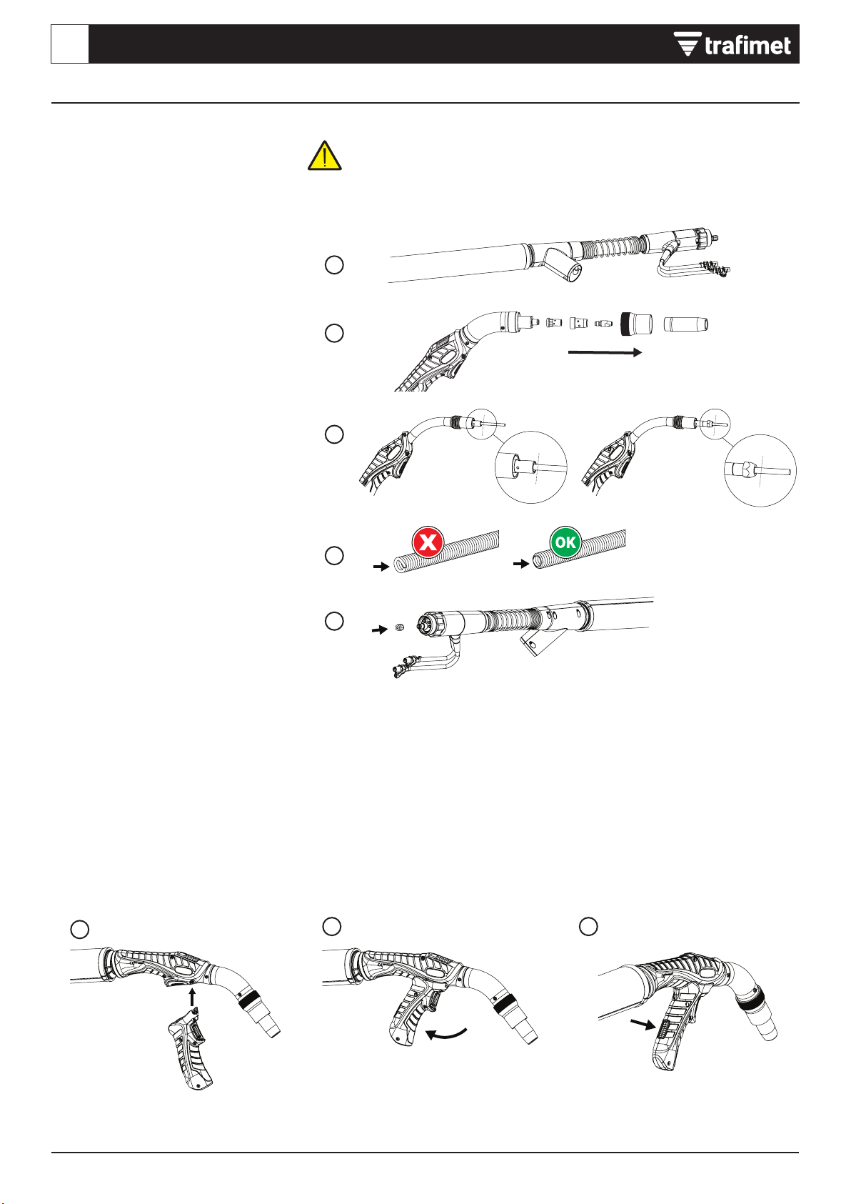
Montaggio della torcia
Selezionare le parti consumabili in base alla
propria applicazione di saldatura.
1. Fissare l’adattatore per punta di contatto
e serrare a mano in posizione. Per
garantire una connessione serrata tra la
punta di contatto e la torcia, è importante
serrare l'adattatore in modo appropriato.
2. Montare la punta di contatto e ssarla
con la chiave.
3. Si noti che quando si collega il diffusore,
l'ordine di assemblaggio varia a causa
delle differenze tra i modelli di torcia.
Assicurarsi che la molla di bloccaggio
siaall'interno dell'ugello dell'aspiratore.
4. Collegare l'ugello dell'aspiratore e
serrarlo quanto basta per tenerlo in
posizione.
5. Collegare l'ugello del gas e serrare
l'ugello dell'aspiratore (stringendo
l'ugello dell'aspiratore si ssano in
posizione sia l'ugello del gas che
l'ugellodell'aspiratore).
Collegamento della torcia
1) Collegare la torcia alle attrezzature di
saldatura. Fissare il connettore ruotando
il collare in senso orario.
2) Solo modelli con raffreddamento
aliquido: Collegare i tubi essibili
di ingresso e uscita del refrigerante
all’attrezzatura di saldatura.
Si noti che i connettori seguono una
codica a colori.
3) Collegare il tubo essibile della torcia
al tubo essibile collegato all'unità
di estrazione fumi. Se necessario,
assicurare il collegamento con il nastro.
Serrare manualmente i connettori della torcia. I connettori allentati possono
surriscaldarsi, creare disturbi nei contatti, danni meccanici e perdite di acqua o gas.

4
132
1
2
3
4
5
1 - 2 mm
1 - 2 mm
Tutti i marchi sono di proprietà dei rispettivi proprietari. Le informazioni e le immagini sono indicative e possono essere soggette a modiche
in qualunque momento senza preavviso. ©2023 Tramet Group SpA
IT TORCIA DI SALDATURA MIG ERGOFRESH
INSTALLAZIONE
Installazione e sostituzione della guaina
guidalo
Le torce di saldatura MIG ERGOFRESH
vengono fornite con la guaina in lo
metallico preinstallata. Consultare questa
sezione quando è necessario sostituire la
guaina in lo metallico. La guaina guidalo
è un materiale di consumo che deve essere
cambiato in caso di usura o quando si
cambia il materiale del lo.
Se si cambia il lo d'apporto con un lo di diametro o materiale diverso, è
necessario cambiare anche i rulli di alimentazione nel sistema trainalo.
Prima di sostituire la guaina guidalo, è necessario rimuovere il lo di apporto.
1. Raddrizzare il cavo della torcia di
saldatura e rimuovere il dado della
guaina.
2. Rimuovere l’ugello del gas e la punta di
contatto. Se la guaina in lo metallico
non passa attraverso il supporto della
punta, rimuovere anche il supporto della
punta.
3. Tagliare la guaina in lo metallico
lasciando 1-2 mm di guaina in eccesso.
4. Rimuovere i bordi ruvidi che potrebbero
danneggiare il lo di apporto.
5. Riavvitare il dado della guaina in
posizione e serrarlo con uno strumento.
Installazione e rimozione
dell’impugnatura della torcia
1. Mantenendo la parte inferiore
dell'impugnatura rivolta in avanti,
inserire le relative scanalature
sopral'impugnatura della torcia.
2. Tirare indietro l'impugnatura indietro
perbloccarla in posizione.
3. Per rimuovere l'impugnatura, premere
il pulsante di blocco situato nella parte
posteriore dell'impugnatura.
5
1 2 3
1
2
3
1 2
Tutti i marchi sono di proprietà dei rispettivi proprietari. Le informazioni e le immagini sono indicative e possono essere soggette a modiche
in qualunque momento senza preavviso. ©2023 Tramet Group SpA
INSTALLAZIONE
Sostituzione dell'ugello dell'aspiratore
edella molla di bloccaggio
L'ugello dell'aspiratore e la molla di
bloccaggio sono parti consumabili che,
seusurate, devono essere sostituite.
1. Svitare e rimuovere il vecchio ugello
dell'aspiratore.
2. Inserire la molla di bloccaggio nel
nuovo ugello dell'aspiratore. Attaccare
il nuovo ugello dell'aspiratore e iniziare
ad avvitarlo. Il serraggio dell'ugello
dell'aspiratore verrà effettuato come
azione nale dopo l'inserimento
dell'ugello del gas.
Sostituzione dell'ugello del gas
L'ugello del gas è un materiale di consumo
che, se usurato, deve essere sostituito.
1. Allentare l'ugello dell'aspiratore
erimuovere il vecchio ugello del gas.
2. Inserire il nuovo ugello del gas.
3. Stringere l'ugello dell'aspiratore per
bloccare in posizione il nuovo ugello del
gas. Tenere la torcia con la punta rivolta
verso l'alto per facilitare il serraggio.
Sostituzione del coperchio del tubo
essibile dell'aspiratore
Il tubo essibile della torcia di saldatura
ERGOFRESH è dotato di una copertura
inpelle ssata con fascette.
La copertura in pelle del tubo essibile
dell'aspiratore è un materiale di consumo
che, se usurato, deve essere sostituito.
1. Rimuovere la vecchia copertura in pelle.
2. Avvolgere la nuova copertura in pelle
attorno al tubo essibile dell'aspiratore.
3. Bloccare la chiusura a strappo e le due
fascette per cavi alle estremità.
NOTA! Tutte le parti devono essere installate. Non rimuovere o modicare alcuna
parte durante la saldatura.
L'ugello del gas esce se l'ugello dell'aspiratore non è installato.
6
1 2 3
Tutti i marchi sono di proprietà dei rispettivi proprietari. Le informazioni e le immagini sono indicative e possono essere soggette a modiche
in qualunque momento senza preavviso. ©2023 Tramet Group SpA
IT TORCIA DI SALDATURA MIG ERGOFRESH
FUNZIONAMENTO
Prima di usare la torcia, accertarsi che tutti i cavi siano in buone condizioni e che
iconnettori siano ssati correttamente.
Non piegare i cavi e i tubi essibili per evitare danni che potrebbero impedire
lacorretta circolazione del gas e del refrigerante.
Controllare prima della saldatura
1. Controllare che il cavo di ritorno a terra
sia collegato all'attrezzatura di saldatura
e al pezzo da saldare.
2. Vericare che il lo di apporto sia idoneo
all’applicazione.
3. Per avviare la saldatura, premere
l'interruttore di saldatura sull'impugnatura
della torcia di saldatura.
Le radiazioni e gli spruzzi dell'arco di saldatura possono causare danni agli
occhi ealla pelle, se non vengono protetti. Durante la saldatura, indossare
sempre il casco da saldatore con la protezione per gli occhi, nonché calzature,
abbigliamento eguanti protettivi.
Informazioni importanti su come utilizzare la torcia di saldatura MIG in modo
sicuro. Classicazione dei comandi elettrici della torcia: 32 V DC 0,05 A.
Alimentazione dell'unità di raffreddamento per torce raffreddate ad acqua:
almeno 800 W.
Misurazione del usso d'aria per
l'estrazione dei fumi
Prima della saldatura, misurare il usso
d'aria per l'estrazione dei fumi con un
misuratore di portata d'aria per l'estrazione
dei fumi. Il usso d'aria deve essere
misurato con la torcia in posizione verticale.
1. Inserire l'ugello dell'aspiratore della torcia
per saldatura nel misuratore di portata
d'aria per l'estrazione dei fumi.
2. Attivare l'estrazione dei fumi.
3. Vericare che l'O-ring rosso sia
posizionato nella zona verde (aspirazione
ottimale dei fumi) in base al modello
di torcia (vedi immagine sopra del
contatore di usso)
Flusso d'aria per l'estrazione dei fumi
Le torce per l'estrazione dei fumi devono
fornire la quantità adeguata di gas di
protezione per evitare che la saldatura
presenti difetti senza compromettere
l'efcienza di cattura dei fumi della torcia.
Se il usso d'aria per l'estrazione dei fumi
è troppo forte, cattura il gas di protezione.
Se il usso d'aria per l'estrazione dei
fumi è troppo debole, non cattura i fumi
di saldatura in modo sufcientemente
efcace.
Diminuzione del usso d'aria per
l'estrazione dei fumi
Per diminuire il usso d'aria per l'estrazione
dei fumi, utilizzare la valvola bypass del
usso d'aria sull'impugnatura della torcia.
La valvola bypass deve normalmente essere
chiusa e aperta solo quando l'estrazione
disturba il usso del gas di protezione, ad
esempio quando ci si avvicina all'angolo
delle piastre.
Per la regolazione del usso d'aria per l'estrazione fumi sull'unità di estrazione fumi,
fare riferimento ai manuali operativi del produttore dell'unità di estrazione fumi.
*Flusso d'aria per l'estrazione dei fumi
Cattura inefciente
Rischio di difetti di
saldatura
Ottimale Ottimale
Conformità
7
0...15° 0...15°
Tutti i marchi sono di proprietà dei rispettivi proprietari. Le informazioni e le immagini sono indicative e possono essere soggette a modiche
in qualunque momento senza preavviso. ©2023 Tramet Group SpA
Ottimizzazione dell'efcienza
dell'estrazione dei fumi
I seguenti fattori aiutano a massimizzare
l'efcienza dell'estrazione dei fumi di una
torcia per saldatura ERGOFRESH.
Posizioni di saldatura e tipi di giunti
La posizione più efcace per
l'estrazione dei fumi è la posizione
piatta perché i fumi salgono
naturalmente verso l'alto.
L'ottimizzazione migliore è mostrata a sinistra.
Materiale del lo e angolo della torcia
Se si utilizzano li pieni, saldare con un
angolodi spinta della torcia di 0...15°.
Se si utilizzano li animati, saldare con un
angolo di trazione della torcia di 0...15°.
Effetto dell'altitudine
Se l'utente si trova ad un'altitudine superiore
a0 m sul livello del mare, la torcia richiede una
pressione negativa inferiore per raggiungere
ilusso d'aria richiesto all'ugello.
La pressione negativa richiesta a diverse
altitudini viene calcolata con la formula fx
pressione negativa (kPa). Vedere Dati tecnici
per informazioni sulla pressione negativa per
ciascun modello di torcia.
FUNZIONAMENTO
Le seguenti gure mostrano in che modo i tipi di giunti inuiscono sull'efcienza
dicattura dei fumi.
Fattore effetto dell'altitudine
Altitudine, z m Fattore, f
01.00
250 0.97
500 0.94
750 0.91
1000 0.89
1250 0.86
1500 0.83
1750 0.81
2000 0.78
2250 0.76
2500 0.74

8Tutti i marchi sono di proprietà dei rispettivi proprietari. Le informazioni e le immagini sono indicative e possono essere soggette a modiche
in qualunque momento senza preavviso. ©2023 Tramet Group SpA
IT TORCIA DI SALDATURA MIG ERGOFRESH
Manutenzione quotidiana
Sulla parte frontale della torcia vericare
che:
1. Tutti gli isolamenti siano integri e intatti.
2. L'ugello del gas sia intatto e adatto
all'operazione da eseguire.
3. Il gas di protezione uisca liberamente
ecostantemente.
4. Il lo di apporto sia intatto e adatto
all'operazione da eseguire.
5. Le parti di ssaggio sono intatte
essate saldamente in posizione.
6. Vericare tutti i cavi e i connettori.
Nonutilizzarli se sono danneggiati.
Sul cavo della torcia vericare che:
1. Gli isolamenti del cavo della torcia
eiconnettori siano intatti.
2. Non ci siano curve a gomito nel cavo
della torcia.
3. I componenti siano ssati saldamente.
4. Controllare che la supercie di
trasferimento della corrente sul
connettore della torcia sia pulita
enondanneggiata.
5. Vericare se il tubo di protezione
delcavo presenta eventuali danni.
Manutenzione periodica
La manutenzione periodica può
essere effettuata esclusivamente
da personale di assistenza
qualicato.
I connettori elettrici dell'unità devono essere
controllati almeno una volta ogni seimesi.
Periodicamente è necessario anche
pulire eventuali parti ossidate e serrare
iconnettori allentati.
MANUTENZIONE
Spegnere l'attrezzatura di saldatura e scollegare la torcia di saldatura prima di eseguire la manutenzione della torcia. La sostituzione
delle parti di ricambio o attività di manutenzione di altro tipo devono essere effettuate dopo il raffreddamento della torcia.
Per eventuali riparazioni, rivolgersi a un rivenditore autorizzato o a un'ofcina di assistenza.
Informazioni generali
La saldatura non si avvia:
• Vericare che il cavo di ritorno a terra
siacollegato correttamente.
• Vericare che anche il sistema
disaldatura funzioni in modo
appropriato.
Il sistema di saldatura smette di funzionare:
• La torcia potrebbe essersi surriscaldata.
Attendere che si raffreddi.
• Vericare che i cavi non si siano allentati.
Torcia di saldatura
La torcia si surriscalda:
• Accertarsi che il corpo torcia sia
collegato correttamente.
• Accertarsi che i parametri di saldatura
siano compresi nell'intervallo della torcia
di saldatura. Se diversi componenti
della torcia hanno limiti separati per la
corrente massima, il valore più basso tra
i due è la corrente massima utilizzabile.
• Assicurarsi che la circolazione del
refrigerante funzioni normalmente
(consistemi raffreddati ad acqua).
• Accertarsi di utilizzare materiali di
consumo e ricambi originali Tramet.
Anche l'uso di materiali di ricambio
erratipuò causare surriscaldamento.
• Assicurarsi che i connettori siano puliti,
non danneggiati e correttamente ssati.
Qualità della saldatura
Saldatura sporca e/o di scarsa qualità:
• Vericare che il gas di protezione non
siaesaurito.
• Vericare che la portata del gas di
protezione non subisca ostruzioni.
• Vericare che il tipo di gas sia idoneo
all'applicazione.
• Vericare che la procedura di saldatura
sia idonea all'applicazione.
Prestazioni di saldatura variabili:
• Controllare le dimensioni, il tipo e l'usura
del lo di apporto.
• Vericare che la torcia di saldatura non
sistia surriscaldando.
• Vericare che il morsetto di messa
aterra sia collegato correttamente
aduna supercie pulita del pezzo.
L'arco non si accende:
• Il tubo di protezione o un altro
isolamento della torcia è rotto.
• La torcia è bagnata.
Lo scudo di gas non è ottimale (il bagno
disaldatura "bolle", l'elettrodo si ossida):
• Ci sono impurità nel gas di protezione
(umidità, aria).
• Ci sono impurità nel materiale di base
(ruggine, fondo, grasso).
• Impurità attaccate all'ugello del gas.
RISOLUZIONE DEI PROBLEMI
L'elenco dei problemi indicati, e delle loro possibili cause, non è completo, ma suggerisce alcune situazioni tipiche che possono
presentarsi durante il normale utilizzo dell'attrezzatura di saldatura. Per assistenza e ulteriori informazioni, rivolgersi al rivenditore
autorizzato più vicino o all'ofcina di assistenza.
9
Tutti i marchi sono di proprietà dei rispettivi proprietari. Le informazioni e le immagini sono indicative e possono essere soggette a modiche
in qualunque momento senza preavviso. ©2023 Tramet Group SpA
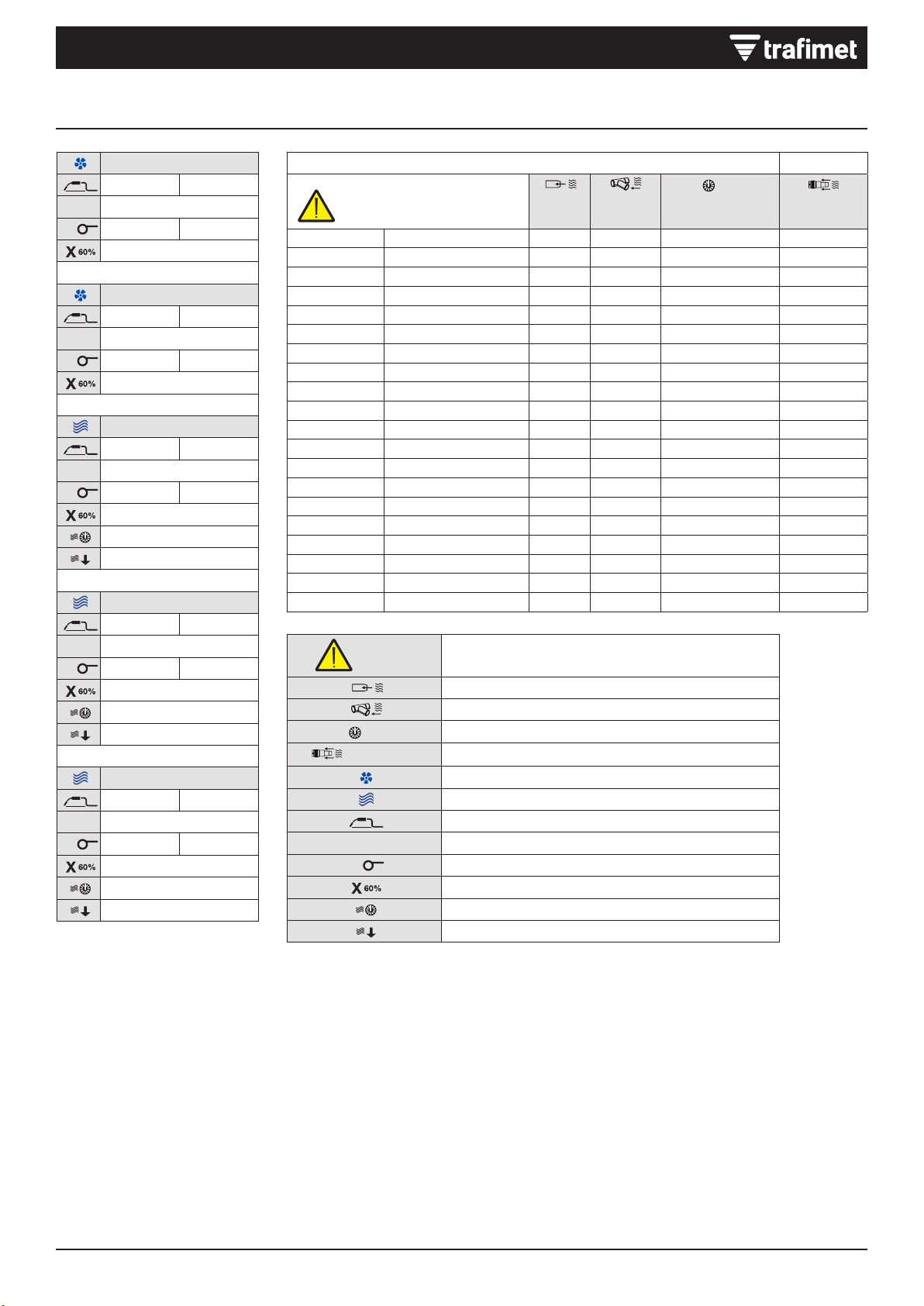
DATI TECNICI
0,35m/sec Velocità minima di acquisizione
Ugello del usso
Connettore del usso
MIN
DIFF
MAX
Pressione negativa al connettore
(ISO 21904-3) Efcienza
Raffreddamento ad aria
Raffreddamento ad acqua
1 m Peso della torcia MIG ad 1 metro di altezza
PEAK
VClasse di tensione
ØDiametro lo
Ciclo di lavoro al 60%
Pressione dell'aria
Portata minima del refrigerante
ERGOFRESH 200G
1 m 1.3 kg 2,87 lb
PEAK
V113
Ø0,8 ÷ 1,2 mm .030” ÷ 0.45”
200A CO2 - 180A Mix
ERGOFRESH 350G
1 m 1.8 kg 3,97 lb
PEAK
V113
Ø0,8 ÷ 1,6 mm .030” ÷ 1/16”
330A CO2 - 300A Mix
ERGOFRESH 300W
1 m 1.5 kg 3,31 lb
PEAK
V113
Ø0,8 ÷ 1,2 mm .030” ÷ .045”
300A CO2 - 250A Mix
2÷4 bar
1.6 l/min
ERGOFRESH 500W
1 m 1.65 kg 3,64 lb
PEAK
V113
Ø1,0 ÷ 2,4 mm .040” ÷ 3/32”
500 A CO2 - 450 A miscela
2÷4 bar
1.6 l/min
ERGOFRESH 555W
1 m 1.65 kg 3,64 lb
PEAK
V113
Ø1,0 ÷ 2,4 mm .040” ÷ 3/32”
550A CO2 - 500A Mix
2÷4 bar
1.6 l/min
(ISO 21904-1) (ISO 21904-3)
Velocità minima di acquisizione
0,35m/s
Ugello del
usso Connettore
del usso
MIN
DIFF
MAX
Pressione negativa
al connettore Efcienza
m³/h m³/h kPa
MA4250-030 ERGOFRESH 200G 3m 48.8 61 2.4 89%
MA4250-040 ERGOFRESH 200G 4m 48.8 66 2.5 89%
MA4250-050 ERGOFRESH 200G 5m 48.8 66 2.7 89%
MA4251-030 ERGOFRESH 350G 3m 44.5 60 2.3 89%
MA4251-040 ERGOFRESH 350G 4m 44.5 56 2.3 89%
MA4251-050 ERGOFRESH 350G 5m 44.5 60 2.6 89%
MB2650-030 ERGOFRESH 300W 3m 48.8 60.6 3.4 90%
MB2650-040 ERGOFRESH 300W 4m 48.8 63.4 3.7 90%
MB2650-050 ERGOFRESH 300W 5m 48.8 67 4.1 90%
MB2651-030 ERGOFRESH 500W 3m 42 54.2 2.8 90%
MB2651-040 ERGOFRESH 500W 4m 42 54 2.9 90%
MB2651-050 ERGOFRESH 500W 5m 42 56.8 3.5 90%
MB2652-030 ERGOFRESH 555W 3m 42 54.6 3.2 90%
MB2652-040 ERGOFRESH 555W 4m 42 54.8 3.3 90%
MB2652-050 ERGOFRESH 555W 5m 42 55.6 3.5 90%

2
EN 60974-7
ISO 21904-3
ISO 21904-1
1
2
2
3
3
1
4
4
5
5
200G/350G/300W
500W/555W
All trademarks are the property of their respective owners. The information and images are indicative and may be subject to change at any time without notice.
© 2023 Tramet Group SpA
EN ERGOFRESH MIG WELDING TORCH
DECLARATION OF CONFORMITY
Tramet Group Spa, a duly registered Italian Manufacturing Company, located in Via del Lavoro, 8 36020 Castegnero (VI),
hereby declares that products identied and described in this manual are in conformity with the provisions of Low Voltage
Directive 2014/35 EU and in compliance with the standards set by EN 60974-7 Arc Welding Equipment - Part 7.
Tramet Group Spa, a duly registered Italian Manufacturing Company, located in Via del Lavoro, 8 36020 Castegnero (VI),
hereby declares that the products identied and described in this manual comply with the provisions of the Electrical
Equipment (Safety) Regulations 2016 and the Restriction of the Use of Certain Hazardous Substances in Electrical and
Electronic Equipment Regulations 2012.
IMPORTANT NOTES
Always use the original Tramet spare parts and consumables.
Read the instructions through carefully. For your own safety, and that of your working environment, pay particular attention to the
safety instructions delivered with the equipment.
Dispose of this product responsibly after use. Torches and used parts should be properly recycled according to the local
requirements and regulations.
Disconnect the power source from the mains power supply before handling electrical cables or performing torch maintenance.
Before connecting the torch, switch off the power source, disconnect the power plug and turn off the gas supply.
Items in the manual that require particular attention in order to minimize damage and harm are indicated with the below symbols. Read
these sections carefully and follow their instructions.
Note: Gives a useful piece of information.
Caution: Describes a situation that may result in damage to the equipment or system.
Warning: Describes a potentially dangerous situation. If not avoided, it will result in personal damage or fatal injury.
ABOUT EQUIPMENT
ERGOFRESH manual MIG/MAG welding torches are designed for welding low- and high-alloyed materials. ERGOFRESH welding torches
capture welding fumes at the arc, cleaning the welder’s breathing zone. ERGOFRESH range covers both water-cooled and gas-cooled
models for MIG welding. Fume extraction torches are used in conjunction with a fume extraction unit. ERGOFRESH welding torches are
compatible with fume extraction units of most major manufacturers. For more information, refer to the fume extraction unit manufacturer’s
documentation.
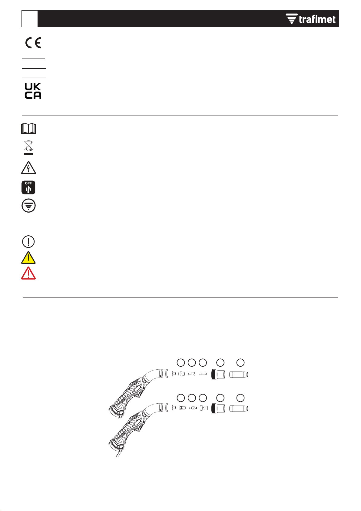
The equipment consists of (the exact visual details may differ between different torch models):
1) Gas diffuser
2) Contact tip holder
3) Contact tip
4) Vacuum nozzle
5) Gas nozzle

3
1
2
3
4
5
200G/350G/300W
500W/555W
All trademarks are the property of their respective owners. The information and images are indicative and may be subject to change at any time without notice.
© 2023 Tramet Group SpA
INSTALLATION
Ensure that the welding equipment is not connected to the mains when installing the equipment.
Ensure compliance with your local and national safety requirements regarding the installation and use of high voltage units.
Check the contents of the packages and make sure the parts are not damaged.
Do not modify or make structural changes to the torch or torch components.
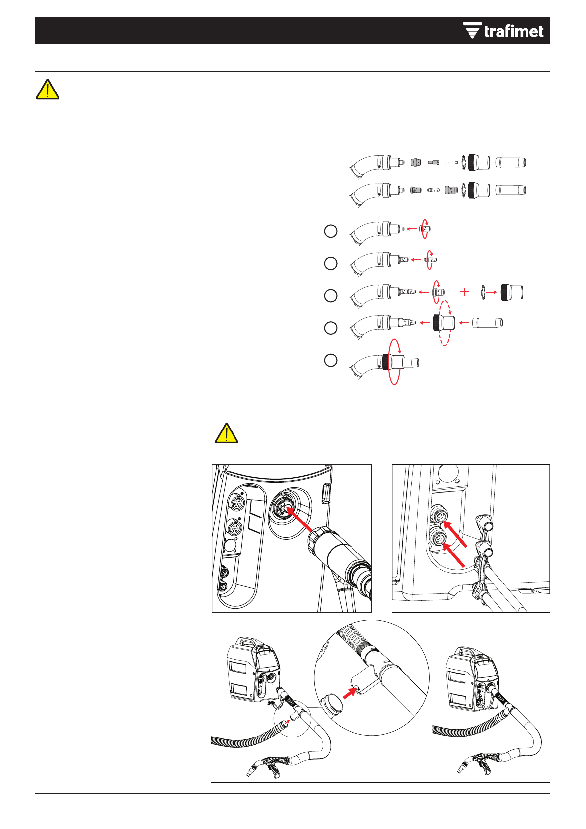
Assembling torch
Select consumable parts according to your
welding application.
1. Attach the contact tip adapter and hand-
tighten it rmly in place. It is important to
tighten the adapter properly to enable a
tight connection of the contact tip to the
torch.
2. Attach the contact tip and secure it with
the spanner.
3. Note that when attaching the diffuser, the
assembly order varies due to differences
between torch models. Make sure that
the locking spring is inside the vacuum
nozzle.
4. Attach the vacuum nozzle and tighten
only enough to hold it in place.
5. Attach the gas nozzle and tighten the
vacuum nozzle (tightening the vacuum
nozzle tightens both the gas nozzle and
the vacuum nozzle in place).
Connecting torch
1) Connect the torch to your welding
equipment. Secure the connector in
place by turning the collar clockwise.
2) Water-cooled models only: Connect the
coolant inlet and outlet hoses to your
welding equipment.
Note that the connectors are color-
coded.
3) Connect the vacuum hose of the torch
to the hose connected to the fume
extraction unit. If necessary, secure the
connection with tape.
Hand tighten the torch connectors. Loose connectors may overheat, create contact
disturbances, mechanical damage and water or gas leakage.
4
132
1
2
3
4
5
1 - 2 mm
1 - 2 mm
All trademarks are the property of their respective owners. The information and images are indicative and may be subject to change at any time without notice.
© 2023 Tramet Group SpA
EN ERGOFRESH MIG WELDING TORCH
INSTALLATION
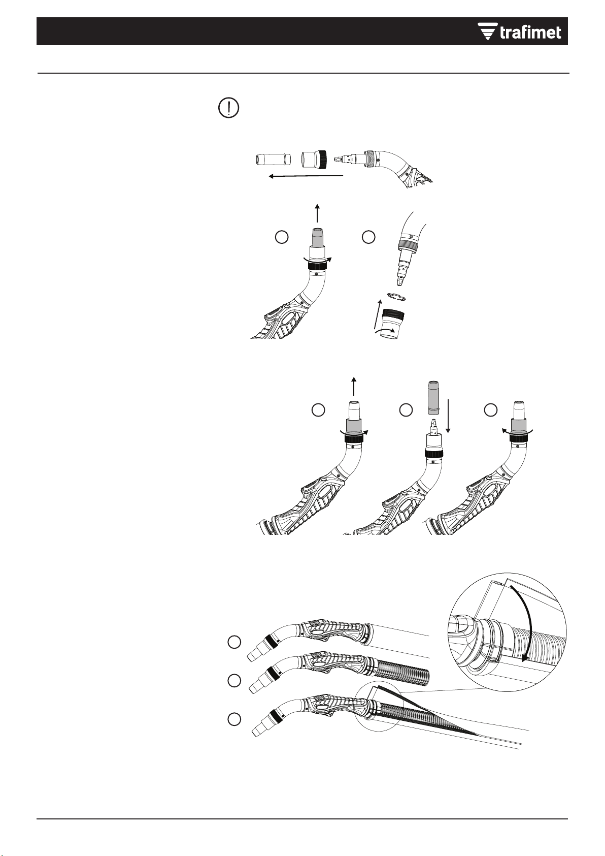
Installing and replacing wire liner
ERGOFRESH MIG welding torches are
delivered with the wire liner preinstalled.
Refer to this section when the wire liner
needs to be replaced. The wire liner is
a consumable part, which needs to be
changed if worn and when the ller wire
material changes.
If you change the ller wire to a different diameter or material, change also the feed
rolls in the wire feed system accordingly.
The ller wire must be removed before the wire liner replacement.
1. Straighten the welding torch cable and
remove the liner nut.
2. Remove the gas nozzle and the contact
tip. If the wire liner does not pass
through the tip holder, remove the tip
holder as well.
3. Cut the wire liner leaving 1-2 mm of
excess liner.
4. Remove any rough edges that could
potentially damage the ller wire.
5. Screw the liner nut back in place and
tighten it with a tool.
Installing and removing grip handle
1. Keeping the bottom of the grip handle
pointing forward, t the grooves of the
grip handle over on the torch handle.
2. Pull the handle backward to lock it in
position.
3. To remove the grip handle, press the lock
button in the grip handle rear.

5
1 2 3
1
2
3
1 2
All trademarks are the property of their respective owners. The information and images are indicative and may be subject to change at any time without notice.
© 2023 Tramet Group SpA
INSTALLATION
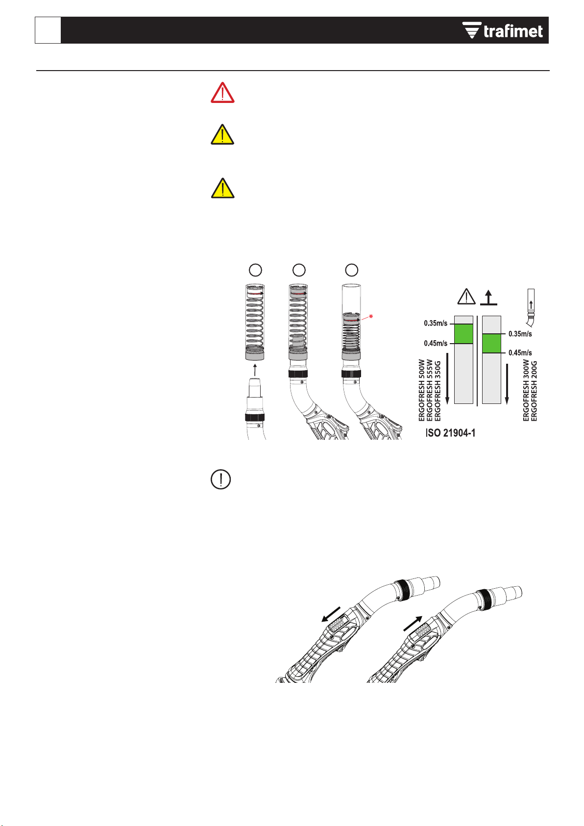
Replacing vacuum nozzle and lock spring
The vacuum nozzle and the locking spring
are consumable parts, which need to be
changed if worn.
1. Unscrew and remove the old vacuum
nozzle.
2. Insert the locking spring into the new
vacuum nozzle. Attach the new vacuum
nozzle and start screwing it. Tightening
of the vacuum nozzle will be done as
nal action after inserting gas nozzle.
Replacing gas nozzle
The gas nozzle is a consumable part, which
needs to be changed if worn.
1. Loosen the vacuum nozzle and remove
the old gas nozzle.
2. Insert the new gas nozzle.
3. Tighten the vacuum nozzle to lock the
new gas nozzle in place. Hold the torch
with the tip up to make tightening easier.
Replacing vacuum hose cover
ERGOFRESH welding torch’s vacuum hose
comes with a leather cover, attached with
cable ties.
The vacuum hose leather cover is a
consumable part, which needs to be
changed if worn.
1. Remove the old leather cover.
2. Wrap the new leather cover around the
vacuum hose.
3. Close the hook-and-loop fastener and the
two cable ties on the ends.
NOTE! All parts must be installed. Do not remove or adjust any parts during
welding.
The gas nozzle comes out if the vacuum nozzle is not installed..

6
1 2 3
All trademarks are the property of their respective owners. The information and images are indicative and may be subject to change at any time without notice.
© 2023 Tramet Group SpA
EN ERGOFRESH MIG WELDING TORCH
OPERATION
Before using the torch, ensure that all the cables are in serviceable condition and
that the connectors are correctly fastened.
Do not bend cables and hoses in order to avoid damages that may prevent proper
gas and coolant circulation.
Check before welding
1. Check that the earth return cable is
connected to the welding equipment and
to the piece to be welded.
2. Check that the ller wire size is suitable
for the job.
3. To start welding, press the welding
switch on the welding torch handle.
The welding arc radiation and spatters cause damage to eyes and unprotected skin.
Always wear welding helmet with eye protection, protective gloves, clothing and
footwear when welding.
Important information on the safe use of the MIG welding torch. Rating of electrical
controls incorporated in the torch: 32VDC 0.05A.
Cooling unit power for water-cooled torches: Minimum 800W.
Measuring fume extraction air ow
Before welding, measure the fume
extraction air ow with a fume extraction
air ow meter. Air ow should be measured
with torch in vertical position.
1. Insert the vacuum nozzle of the welding
gun into the fume extraction air ow
meter.
2. Turn the fume extraction on.
3. Check that the red O-ring is placed in
the green area (optimal fume extraction)
according to the torch model (see the
above image of the ow meter)
Fume extraction air ow
Fume extraction torches need to provide
the appropriate amount of shielding gas
to protect the weld from defects without
compromising the fume capture efciency
of the torch. If the fume extraction air ow
is too strong, it captures shielding gas. If
the fume extraction air ow is too weak, it
doesn’t capture welding fumes effectively
enough.
Decreasing fume extraction air ow
To decrease the fume extraction air ow,
use the air ow bypass valve on the torch
handle. The bypass valve should normally
be closed and opened only when extraction
disturbs the shielding gas ow, for example
when approaching the corner of the plates.
For adjusting the fume extraction air ow at the fume extraction unit, refer to the
operating manuals of the fume extraction unit manufacturer.
* Fume extraction air ow
Poor capture
Risk of weld defect
Optimal Optimal
Accordance

7
0...15° 0...15°
All trademarks are the property of their respective owners. The information and images are indicative and may be subject to change at any time without notice.
© 2023 Tramet Group SpA
OPERATION
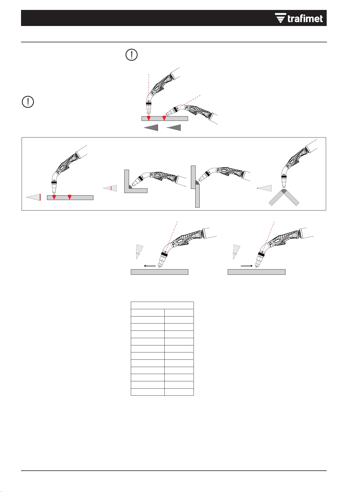
The following gures display how joint types affect fume capture efciency.
Optimizing fume extraction efciency
The following factors help maximizing the
fume extraction efciency of a ERGOFRESH
welding gun.
Welding positions and joint types
The most effective position for
fume extraction is the at position
because the fumes naturally rise
upward.
The best optimization is shown on the left.
Wire material and gun angle
When welding with solid wires, weld with a
0 ... 15° pushing torch angle.
When welding with ux-cored wires, weld
with a 0 ... 15° pulling torch angle.
Effect of altitude
If the user is at a higher altitude than 0 m
above sea level, the torch requires a lower
negative pressure to reach the required air
ow at the nozzle.
The required negative pressure in different
altitudes is calculated with formula f x
negative pressure (kPa). See Technical data
for information on the negative pressure for
each torch model.
Effect factor of altitude
Altitude, z
m
Factor, f
01.00
250 0.97
500 0.94
750 0.91
1000 0.89
1250 0.86
1500 0.83
1750 0.81
2000 0.78
2250 0.76
2500 0.74
8All trademarks are the property of their respective owners. The information and images are indicative and may be subject to change at any time without notice.
© 2023 Tramet Group SpA
EN ERGOFRESH MIG WELDING TORCH
Daily maintenance
On the torch front part, check that:
1. All insulations are undamaged and
intact.
2. Gas nozzle is intact and suitable for
work.
3. Shielding gas ows freely and steadily.
4. Filler wire is intact and suitable for work.
5. Fastening parts are intact and fastened
tightly in place.
6. Check all the cables and connectors. Do
not use them if they are damaged.
On the torch cable, check that:
1. Torch cable insulations and connectors
are intact.
2. There are no sharp bends in the torch
cable.
3. Components are tightly fastened.
4. Check that the current transfer surface
on the torch current connector is clean
and undamaged.
5. Check the protective hose on the cable
for damage.
Periodic maintenance
Only qualied service personnel
is allowed to carry out periodic
maintenance.
The electric connectors of the unit require
checks at least every six months. Also
cleansing of any oxidized parts and
tightening loose connectors is required
periodically.
MAINTENANCE
Turn off the welding equipment and disconnect the welding torch before performing torch maintenance. Replacement of spare
parts or other maintenance must be performed after the torch has cooled down.
For any repairs, contact an authorized dealer or service workshop.
General
The welding does not start:
• Check that the earth return cable is
properly connected.
• Check that the welding system is also
otherwise in a proper working order.
The welding system stops working:
• The torch may have overheated. Wait for
it to cool down.
• Check that the cables have not become
loose.
Welding torch
The torch overheats:
• Make sure the torch body is properly
connected.
• Make sure that the welding parameters
are within the range of the welding torch.
If different torch components have
separate limits for the maximum current;
the lower one of these is the maximum
current that can be used.
• Make sure the coolant circulation is
working normally (with water-cooled
systems).
• Make sure you are using original
Tramet consumable and spare parts.
Incorrect spare part materials may also
cause overheating.
• Make sure the connectors are clean,
undamaged and properly fastened.
Weld quality
Dirty and/or poor weld quality:
• Check that the shielding gas has not run
out.
• Check that the shielding gas ow is
unobstructed.
• Check that the gas type is correct for the
application.
• Check that the welding procedure is
correct for the application.
Varying welding performance:
• Check the ller wire size, type and wear.
• Check that the welding torch is not
overheating.
• Check that the earth return clamp is
properly attached to a clean surface of
the workpiece.
Arc is not ignited:
• Protective hose or another insulation of
torch is broken.
• Torch is wet.
Gas shielding is bad (weld pool “boils”,
electrode gets oxidized):
• There are impurities in shielding gas
(moisture, air).
• There are impurities in base material
(rust, base coat, grease).
• Impurities stuck on gas nozzle.
TROUBLESHOOTING
The problems and the possible causes listed are not denitive, but suggest some typical situations that may turn up during normal
use of the welding equipment. For further information and assistance, contact your nearest authorized dealer or service workshop.
9
All trademarks are the property of their respective owners. The information and images are indicative and may be subject to change at any time without notice.
© 2023 Tramet Group SpA
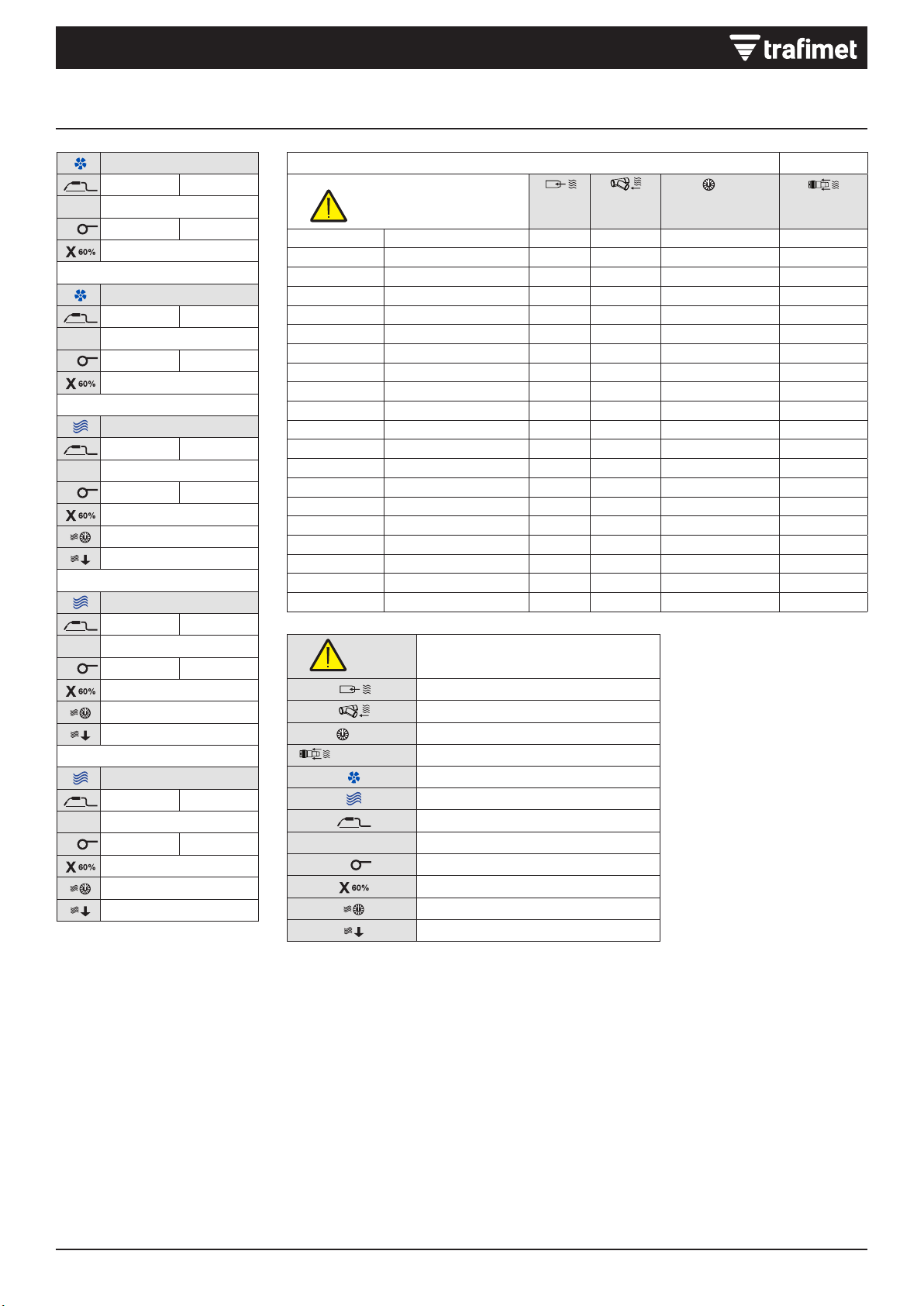
TECHNICAL DATA
0,35m/s Min speed capture
Flow nozzle
Flow connector
MIN
DIFF
MAX
Negative pressure at connector
(ISO 21904-3) Efciency
Air cooling
Water cooling
1 m MIG torch weight at a height of 1 meter
PEAK
VVoltage class
ØWire diameter
Duty cycle @ 60%
Air pressure
Coolant ow rate
ERGOFRESH 200G
1 m 1.3 kg 2.87 lb
PEAK
V113
Ø0.8 ÷ 1.2 mm .030” ÷ 0.45”
200A CO2 - 180A Mix
ERGOFRESH 350G
1 m 1.8 kg 3.97 lb
PEAK
V113
Ø0.8 ÷ 1.6 mm .030” ÷ 1/16”
330A CO2 - 300A Mix
ERGOFRESH 300W
1 m 1.5 kg 3.31 lb
PEAK
V113
Ø0.8 ÷ 1.2 mm .030” ÷ .045”
300A CO2 - 250A Mix
2÷4 bar
1.6 l/min
ERGOFRESH 500W
1 m 1.65 kg 3.64 lb
PEAK
V113
Ø1.0 ÷ 2.4 mm .040” ÷ 3/32”
500A CO2 - 450A Mix
2÷4 bar
1.6 l/min
ERGOFRESH 555W
1 m 1.65 kg 3.64 lb
PEAK
V113
Ø1.0 ÷ 2.4 mm .040” ÷ 3/32”
550A CO2 - 500A Mix
2÷4 bar
1.6 l/min
(ISO 21904-1) (ISO 21904-3)
Min speed capture 0,35m/s Flow
nozzle Flow
connector
MIN
DIFF
MAX
Negative pressure
at connector Efciency
m³/h m³/h kPa
MA4250-030 ERGOFRESH 200G 3m 48.8 61 2.4 89%
MA4250-040 ERGOFRESH 200G 4m 48.8 66 2.5 89%
MA4250-050 ERGOFRESH 200G 5m 48.8 66 2.7 89%
MA4251-030 ERGOFRESH 350G 3m 44.5 60 2.3 89%
MA4251-040 ERGOFRESH 350G 4m 44.5 56 2.3 89%
MA4251-050 ERGOFRESH 350G 5m 44.5 60 2.6 89%
MB2650-030 ERGOFRESH 300W 3m 48.8 60.6 3.4 90%
MB2650-040 ERGOFRESH 300W 4m 48.8 63.4 3.7 90%
MB2650-050 ERGOFRESH 300W 5m 48.8 67 4.1 90%
MB2651-030 ERGOFRESH 500W 3m 42 54.2 2.8 90%
MB2651-040 ERGOFRESH 500W 4m 42 54 2.9 90%
MB2651-050 ERGOFRESH 500W 5m 42 56.8 3.5 90%
MB2652-030 ERGOFRESH 555W 3m 42 54.6 3.2 90%
MB2652-040 ERGOFRESH 555W 4m 42 54.8 3.3 90%
MB2652-050 ERGOFRESH 555W 5m 42 55.6 3.5 90%

2
EN 60974-7
ISO 21904-3
ISO 21904-1
1
2
2
3
3
1
4
4
5
5
200G/350G/300W
500W/555W
ERGOFRESH MIG WELDING TORCHERGOFRESH MIG WELDING TORCHDE
Alle Markenzeichen sind ausschließliches Eigentum der jeweiligen Firmen. Die Informationen und Bilder sind Richtwerte und können
jederzeit ohne Vorankündigung geändert werden. © 2023 Tramet Group SpA
KONFORMITÄTSERKLÄRUNG
Tramet Group Spa, ein ordnungsgemäß eingetragenes italienisches Produktionsunternehmen mit Sitz in der Via del Lavoro,
8 36020 Castegnero (VI), erklärt hiermit, dass die in diesem Handbuch bezeichneten und beschriebenen Produkte den
Bestimmungen der Niederspannungsrichtlinie 2014/35 EU und den von der EN 60974-7 Lichtbogenschweißeinrichtungen–
Teil7 festgelegten Normen entsprechen.
Tramet Group Spa, ein ordnungsgemäß eingetragenes italienisches Produktionsunternehmen mit Sitz in der Via del Lavoro,
8 36020 Castegnero (VI), erklärt hiermit, dass die in diesem Handbuch bezeichneten und beschriebenen Produkte den
Bestimmungen im Hinblick auf die Sicherheit von Elektrogeräten aus dem Jahr2016 und der Beschränkung der Verwendung
bestimmter Gefahrenstoffe in Elektro- und Elektronikgeräten aus dem Jahr2012 entsprechen.
WICHTIGE HINWEISE
Verwenden Sie immer die Original-Ersatzteile und Verbrauchsmaterialien von Tramet.
Lesen Sie die Anweisungen aufmerksam durch. Zu Ihrer eigenen Sicherheit und der Ihres Arbeitsumfelds beachten Sie bitte
insbesondere die Sicherheitshinweise, die im Lieferumfang des Geräts enthalten sind.
Entsorgen Sie das Produkt nach Gebrauch verantwortungsbewusst. Brenner und gebrauchte Teile sind immer ordnungsgemäß
entsprechend den geltenden lokalen Anforderungen und Vorschriften zu recyceln.
Trennen Sie die Stromquelle vom Stromnetz, bevor Sie mit elektrischen Kabeln hantieren oder Wartungsarbeiten am Brenner
durchführen.
Schalten Sie vor dem Anschließen des Brenners die Stromquelle aus, ziehen Sie den Netzstecker und schalten Sie die Gaszufuhr ab.
Bemerkungen in diesem Handbuch, denen besondere Aufmerksamkeit geschenkt werden muss, um die Gefahr von Personen- und
Sachschäden zu minimieren, sind mit den nachstehenden Symbolen gekennzeichnet. Lesen Sie diese Abschnitte sorgfältig durch und
befolgen Sie die entsprechenden Anweisungen.
Hinweis: Gibt nützliche Informationen.
Vorsicht: Beschreibt eine Situation, die zu Schäden am Gerät oder am System führen kann.
Achtung: Beschreibt eine möglicherweise gefährliche Situation. Wird diese nicht vermieden, kann es zu schweren oder tödlichen
Verletzungen kommen.
ÜBER DAS GERÄT
Die Handschweißbrenner des Typs ERGOFRESH MIG/MAG sind auf das Schweißen von niedrig- und hochlegierten Werkstoffen ausgelegt.
Die ERGOFRESH-Schweißbrenner saugen den Schweißrauch am Lichtbogen ab und verringern so die Belastung der Atemzone des
Schweißers. Die Reihe ERGOFRESH umfasst sowohl wassergekühlte als auch gasgekühlte Modelle für das MIG-Schweißen. Brenner mit
Rauchgasabsaugung werden in Verbindung mit einer Rauchabsaugungseinheit verwendet. ERGOFRESH Schweißbrenner sind mit den
Rauchabsaugungseinheiten der meisten großen Hersteller kompatibel. Für weitere Informationen, siehe die Dokumentation des Herstellers
der Rauchabsaugungseinheit.
Das Gerät besteht aus (die genauen visuellen Details können bei verschiedenen Brennermodellen unterschiedlich sein):
1) Gasverteiler
2) Düsenstock
3) Stromdüse
4) Absaugdüse
5) Gasdüse
3
1
2
3
4
5
200G/350G/300W
500W/555W
Alle Markenzeichen sind ausschließliches Eigentum der jeweiligen Firmen. Die Informationen und Bilder sind Richtwerte und können
jederzeit ohne Vorankündigung geändert werden. © 2023 Tramet Group SpA
INSTALLATION
Vergewissern Sie sich, dass das Schweißgerät nicht an das Stromnetz angeschlossen ist, wenn Sie das Gerät installieren.
Stellen Sie sicher, dass Ihre örtlichen und nationalen Sicherheitsanforderungen an die Installation und Nutzung von
Hochspannungsgeräten eingehalten werden.
Prüfen Sie den Inhalt der Verpackungen und stellen Sie sicher, dass die Teile nicht beschädigt sind.
Nehmen Sie keine Modikationen oder baulichen Veränderungen am Brenner oder an den Brennerteilen vor.
Montage des Brenners
Wählen Sie die Verschleißteile entsprechend
Ihrer Schweißanwendung aus.
1. Den Düsenstockadapter anbringen
und handfest anziehen. Um eine feste
Verbindung von Stromdüse und Brenner
zu gewährleiten, muss der Adapter
korrekt angezogen werden.
2. Die Stromdüse anbringen und mit dem
Schraubenschlüssel sichern.
3. Hinweis: Beim Anbringen des Verteilers
kann die Montagereihenfolge aufgrund
der Unterschiede zwischen den
Brennermodellen variieren. Sicherstellen,
dass die Sicherungsfeder in der
Absaugdüse sitzt.
4. Die Absaugdüse anbringen und nur so
weit anziehen, dass sie in Einbaulage
gehalten wird.
5. Die Gasdüse anbringen und die
Absaugdüse festziehen (durch
Festziehen der Absaugdüse werden
sowohl die Gasdüse als auch die
Absaugdüse festgezogen).
Anschließen des Brenners
1) Den Brenner an das Schweißgerät
anschließen. Den Anschluss durch
Drehen des Ringes im Uhrzeigersinn
in Einbaulage sichern.
2) Nur üssiggekühlte Modelle: Verbinden
Sie die Ein- und Ausgangsschläuche
für das Kühlmittel mit Ihrer
Schweißmaschine.
Hinweis: Die Anschlüsse sind
farbcodiert.
3) Den Absaugschlauch des
Schweißbrenners mit dem Schlauch an
der Rauchabsaugungseinheit verbinden.
Gegebenenfalls die Verbindung mit
Band sichern.
Ziehen Sie die Brenneranschlüsse handfest an. Lockere Anschlüsse können
überhitzen oder Kontaktstörungen, mechanische Beschädigungen und Wasser-
oder Gasaustritt verursachen.

4
132
1
2
3
4
5
1 - 2 mm
1 - 2 mm
ERGOFRESH MIG WELDING TORCHERGOFRESH MIG WELDING TORCHDE
Alle Markenzeichen sind ausschließliches Eigentum der jeweiligen Firmen. Die Informationen und Bilder sind Richtwerte und können
jederzeit ohne Vorankündigung geändert werden. © 2023 Tramet Group SpA
INSTALLATION
Installieren und Ersetzen des Drahtliners
Die Schweißbrenner des Typs ERGOPLUS
MIG werden mit vormontiertem Drahtliner
geliefert. Lesen Sie vor dem Ersetzen des
Drahtliners diesen Abschnitt. Der Drahtleiter
ist Verbrauchsmaterial und muss ersetzt
werden, wenn er verschlissen ist oder der
Zusatzwerkstoff geändert wird.
Wenn Sie Durchmesser oder Material des Zusatzwerkstoffs ändern, wechseln Sie
auch die Vorschubrollen im Drahtvorschubsystem entsprechend.
Der Fülldraht muss vor dem Einsetzen des neuen Drahtliners entfernt werden.
1. Das Schweißbrennerkabel gerade
ausrichten und die Mutter vom Liner
entfernen.
2. Die Gasdüse und die Stromdüse
entfernen. Falls der Drahtliner nicht durch
den Düsenstock geführt werden kann,
diesen ebenfalls entfernen.
3. Den Drahtliner bis auf 1 bis 2
hervorstehende Millimeter abschneiden.
4. Alle rauen Kanten entfernen, die den
Fülldraht beschädigen könnten.
5. Die Mutter des Liners wieder
anschrauben und mit einem Werkzeug
festziehen.
Installieren und Entfernen des Griffs
(optional)
1. Die Unterseite des Griffs nach vorn
ausrichten und die Nuten des Griffs auf
den Brennergriff setzen.
2. Ziehen Sie den Griff zurück, um ihn zu
arretieren.
3. Um den Griff zu entfernen, den
Sicherungsknopf an der Rückseite des
Griffs drücken.
Other manuals for ERGOFRESH 200G
1
This manual suits for next models
4
Table of contents
Languages:
Other Trafimet Welding Accessories manuals


