4 UNT-PRC002-GB
Technical Data
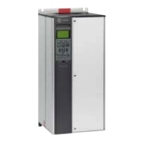
FWD 08 12 20 30 45
Power supply (V/Ph/Hz) 230/1/50
Capacities
Cooling capacity on water (1) (kW) 5,2 8,3 15 18,8 30,1
Heating capacity on water (2) (kW) 6,3 11,9 18,9 20,9 38,2
Fan motor (type) 2 x direct drive centrifugal
Fan power input (3) (kW) 0,23 0,46 0,65 1,04 1,51
Current amps (3) (A) 1,1 2,2 3,1 4,7 5,5
Start-up amps (A) 3,2 5,5 9,3 14,1 16,5
Air flow
minimum (m3/h) 490 980 1400 1800 2700
nominal (m3/h) 820 1650 2300 3000 4500
maximum (m3/h) 980 1970 2600 3600 5400
Main coil
Water entering/leaving connections (type) ISO R7 rotating female
(Dia) 3/4" 3/4" 1 1/2" 1 1/2" 1 1/2"
Electric heater (accessory for blower only)
Electric power supply (V/Ph/Hz) 230/1/50 230/1/50 or 400/3/50 400/3/50 400/3/50 400/3/50
Heating capacity (kW) 2/4 8 10 12 12
Hot water coil (accessory for blower only)
Heating capacity (4) (kW) 6,3 12 17,4 22,4 34,5
G2 filter (filter box accessory)
Quantity 2 2 2 2 2
Dimensions ( LxWxth) (mm) 386x221x8 486x271x8 586x321x8 586*421*8 586*621*8
G4 filter (filter box accessory)
Quantity - 2 2 2 2
Dimensions ( LxWxth) (mm) - 486x264x48 586x314x48 586*414*48 586*614*48
Condensate pump (accessory) (type) Centrifugal
Water flow - lift height (l/h - mm) 24 - 500
Not available for FWD30 and FWD45
Sound level (L/M/H speed)
Sound pressure level (5) (dB(A)) 36/40/43 38/41/44 46/50/53 47/52/57 47/52/58
Sound power level (5) (dB(A)) 46/50/53 48/51/54 56/60/63 57/62/67 57/62/68
Unit dimensions
Width x Depth (mm) 890 x 600 1090 x 710 1290 x 820 1290 x 970 1290 x 1090
Height (mm) 250 300 350 450 650
Shipped unit dimensions
Width x Depth (mm) 933 x 644 1133 x 754 1333 x 864 1333 x 1008 1333*1133
Height (mm) 260 310 360 460 660
Weight (kg) 32 46 61 76 118
Colour galvanised steel
Recommended fuse size
Unit alone (aM/gI) (A) 8/16 8/16 8/16 8/25 8/25
Unit with electric heater (gI) (A) 16 (2kW),25 (4kW) 40 (230V),3*16 (400V) 3*20 3*25 3*25
(1) Conditions: Water entering/leaving temperature: 7/12 °C, Air inlet temperature 27/19°C DB/WB - Nominal air flow
(2) Conditions: Water entering/leaving temperature: 50/45 °C, Air inlet temperature 20°C DB - Nominal air flow
(3) At high speed with nominal air flow.
(4) Water entering/leaving temperature 90/70 °C, air inlet temperature 20 °C DB, Nominal air flow.
(5) A rectangular glass wool duct 1m50 long is placed on the blower.The measurement is taken in the room containing the blower unit.
Heat exchanger operating limits:
FWD:
*water temperature: max 100° C
*absolute service pressure: min 1 bar/max 11 bars
Accessories - Hot water coil:
*water temperature: min. +2° C/max. 100° C
*absolute service pressure: min 1 bar/max 11 bars
Low Voltage Wiring / Ice Making (Optional)
Low Voltage Wiring
The remote devices described below require low voltage
wiring. All wiring to and from these remote input devices
to the Control Panel must be made with shielded,
twisted pair conductors. Be sure to ground the shielding
only at the panel.
Important:
To prevent control malfunctions, do not run low voltage
wiring (<30 V) in conduit with conductors carrying more
than 30 volts.
Emergency Stop
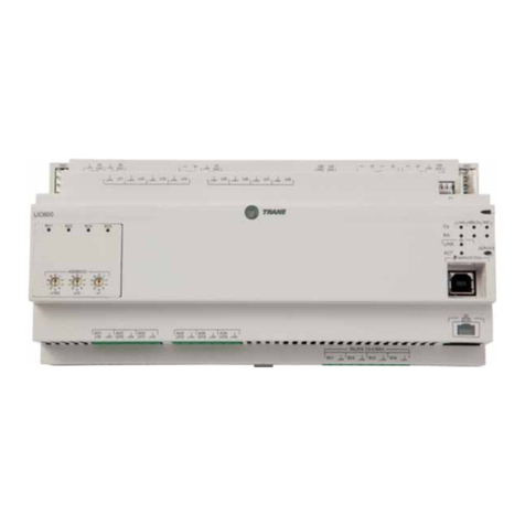
UC800 provides auxiliary control for a customer
specified/installed latching trip out. When customer
furnished remote contact 6S2, the chiller will run
normally when the contact is closed. When the contact
opens, the unit will stop and a manually resettable
diagnostic is generated. This condition requires manual
reset at the chiller switch on the front of the control
panel.
This customer-furnished contact must be compatible
with 24 VDC, 12 mA resistive load.
External Auto/Stop
If the unit requires external Auto/Stop function, the
installer must provide remote contact 6S1.
The chiller will run normally when the contact is closed.
When contact opens, the compressor(s), if operating, will
go to the RUN: UNLOAD operating mode and cycle off.
Unit operation will be inhibited. Closure of the contact
will permit the unit to return to normal operation.
Field-supplied contacts for all low voltage connections
must be compatible with dry circuit 24 VDC for a 12mA
resistive load. Refer to the field diagrams that are
shipped with the unit.
Ice Making (Optional)
When the Ice Making Command is removed (i.e. all
the installed Ice Making inputs are set to “auto”), the
compressors shall be stopped after the run unload
period (if not already stopped due to Ice Making
Complete). The chiller shall return to normal Auto mode
of operation, and allowed to restart only after enforcing
a 2 minute delay called the “Ice to Normal Transition
time”. During this inhibit, the Evaporator water flow
request shall be commanded on. After the delay, the
chiller can restart again per the differential to start and
the normal Chilled Water Setpoint (or Hot Water Setpoint
– if in Heating Mode). The Ice To Normal Transition
inhibit shall be annunciated as a Chiller Submode and a
countdown timer showing the remaining time left shall
be displayed.
Ice Making Configuration:
Ice Making is configured through TU, and there shall be
two installation options:
1. Not Installed
2. Installed with Hardware
Ice Making: Not Installed
If the Ice Building Configuration item is set to ‘Not
Installed’, the application will not build the Ice Making
objects, and will require none of the Ice Making specific
LLIDS.
Ice Making: Installed with Hardware
If the Ice Making Configuration item is set to ‘Installed’,
the application will require the following LLIDs:
• External Ice Making Input (Dual Low Voltage Binary
Input)
Ice Making Setpoints:
After Ice Making is configured, there shall be three Ice
Making Settings or Setpoints:
1. Ice Making Command
2. Ice Making Enable/Disable
3. Ice Making Termination Setpoint
The ice making setpoints can all be manipulated through
TU. Some of the Setpoints can be manipulated with User
Interface on the Display, the External Hardware Interface
BAS (if a BAS is installed).
The setpoints associated with ice making are explained
in more detail below.
Ice Making Command
This is the command to enter ice making. This setting is
defined as an Auto/On settings. Setting this to On will
command the application into ice building if ice building
is enabled and the Chiller is in the “Auto” command
mode. Setting the Ice Making command to Auto will
command the application to follow the next priority
functional mode.
Regardless of the setting of the Setpoint Source (see
setpoint arbitration.doc) any of the following 4 signals
can combine to comprise the Ice Building Command
(assuming they are each installed).
Contact closure input for External Ice Making Command
Front Panel Ice Making Command (also writable from
TU Lontalk Communicated Ice Making Command (LCI-C,
BACnet, Modbus)
Time of Day scheduler
All ice making signals have to be turned to “auto” to be
able to turn back Ice Making Command to “Auto” mode.
The overall Ice Making Command, must be toggled from
“Ice Making”, to “Auto” to “Ice Making” again, before
Ice Making can be entered a second time.
Ice Making Enable/Disable setting
This setting does not start or stop ice building. This is
the command to enable or disable the entire ice building
feature. It can only be set through the Display or TU.
The Ice Making Command starts and stops ice building.
Ice Making Termination setpoint
This setpoint controls when Ice Making is complete. If
the Entering Water Temperature decreases below this
setpoint with no deadband Ice Making will be deemed
complete. This setpoint has a range of –6.7°C (20°F) to
0°C (32°F) with a default of -2.8°C (27°F).
