PTCS Heat Pump Thermostat Support Sheet
Manufacturer: Trane, American Standard
Thermostat Models: XL824, TCONT824, Gold XV, ACONT824, XL850, TCONT850, ACONT850, Platinum 850
Page 2of 3
5. Access Test Mode for testing system at full capacity –
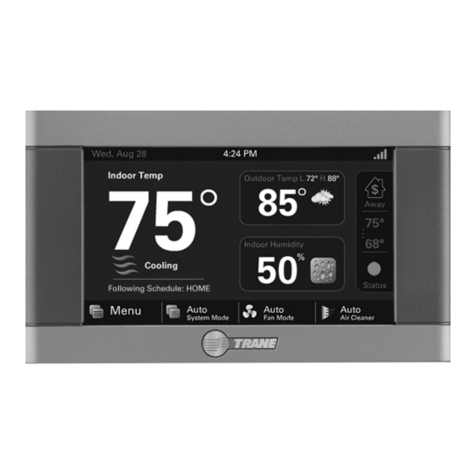
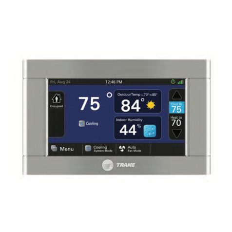
a. Press “MENU” in the lower left corner of the home screen
b. Press "SERVICE" to accessthe service menu
c. Press "TEST MODE"
d. Press "SYSTEM" to select the desired system test:
A. Cooling mode: Select "TEST COOL" followed by “Next” and choose the highest stage available. Press
"TEST" to begin testing in the selected mode
B. Heating mode: Select "TEST COMPRESSOR HEAT" followed by “Next” and choose the highest stage
available. Press the "TEST" button to begin testing in selected mode
C. If the "TEST COMPRESSOR HEAT" option is not displayed, return to the home screen and make a large
call for heat of at least 10 degrees. Please Note: if OAT is less than Auxiliary Heat Lockout temperature
setpoint the auxiliary heat may engage
e. Eachtest will run for a maximum of 60 minutes or until manually terminated
f. Wait at least 10 minutes before taking static pressure readings and inserting flow plate for TrueFlow plate
test. Listen to ensure fan has staged up completely
g. Wait at least 20-25 minutes before doing temp split readings for refrigerant test. The longer the system is
allowed to run, the more likely it will reach a steady state
6. Access Test Mode for testing system at full capacity – Variable Speed Units (Only 850 series)
a. For variable speed systems, this thermostat does not have a test mode that runs compressor and fan at full
capacity for PTCS inspection purposes. To test the system, make a big call (at least 10 degrees) for HEATING
or COOLING depending on the type of test you wish to perform. Please Note: if OAT is less than Auxiliary
Heat Lockout temperature setpoint the auxiliary heat may engage
b. A call for HEATING or COOLING will typically never force the unit into full compressor and fan speed. Use the
following steps to determine the percent of compressor speed the system is operating at:
A. If the Compressor Speed Widget is enabled, the thermostat will display the percent of compressor
speed on the home screen
B. If the Compressor Speed Widget is not displayed on the home screen, from the Service Menu (accessed
in Step 1a-1c) press “System Report”. The percent of compressor speed will be displayed as “%
Delivered”
c. For both methods A and B above, let the system run for at least 20 minutes to reach steady state. Supply
static can be monitored for when the fan ramps to maximum speed
d. Multiply nominal capacity by the Compressor Speed Widget value (%) or “% Delivered” from the “System
Report” to estimate current operating capacity. Use this current operating capacity for airflow CFM/ton
calculations and subsequently for the temp split table. 76% Compressor Speed is usually the maximum
speed achievable
e. Returntemperature settingson the thermostat to where they were when you arrived at the home
7. Exit Test Mode
a. While in test mode, press and hold the center button, followed by “Cancel”
