TransMotion Medical TMM5-X Series User manual
OPERATION MANUAL
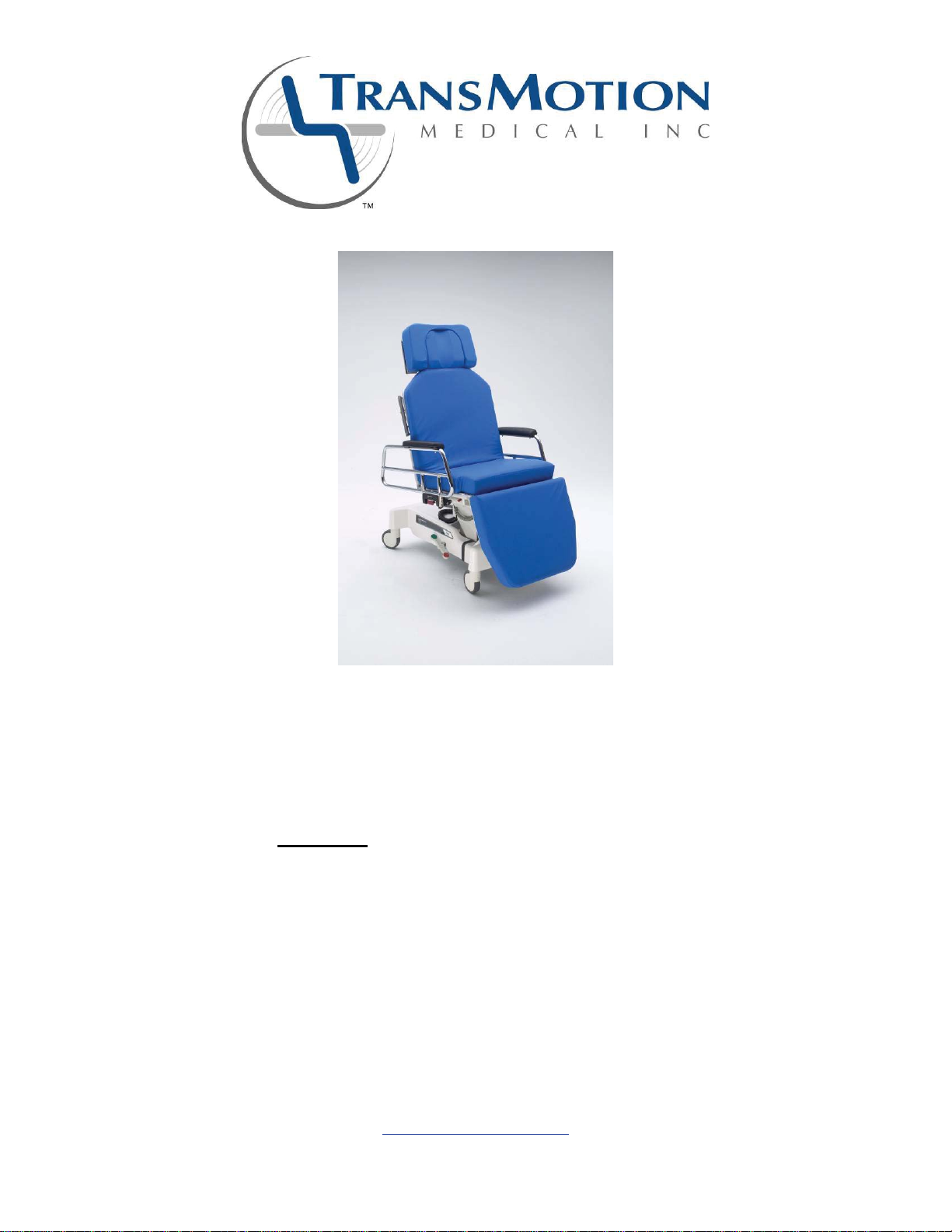
Model TMM5-X Series
Multi-Purpose Tilt Chair and Surgi-Chair II
Options:
WWide
TTall
LLow
F Folding Footrest
EExport
BBattery
AACPower
1441 Wolf Creek Trail - PO Box 302, Sharon Center, OH 44274
Phone: 1-866-860-8447 - Fax: 1-330-239-4465
www.transmotionmedical.com
Document No.: OM TMM5-X SERIES
Revision: T
Page 1 of 26

TABLE OF CONTENTS
IMPORTANT NOTES ABOUT THIS MANUAL.............................................................................3
SPECIAL NOTES - SIGNAL WORDS..........................................................................................3
SAFETY PRECAUTIONS.............................................................................................................4
LABELING DIAGRAMS (TMM5-XTFA shown)...........................................................................8
OPERATING INSTRUCTIONS...................................................................................................10
BACK SECTION QUICK RELEASE.......................................................................................................................10
CASTER BRAKE OPERATION .............................................................................................................................11
SIDE RAIL OPERATION........................................................................................................................................11
ADJUSTING SIDE RAIL ANGLE ...........................................................................................................................12
PENDANT (CONTROLLER) ..................................................................................................................................14
PATIENT INGRESS / EGRESS.............................................................................................................................15
PATIENT TRANSFER............................................................................................................................................15
HEAD EXTENSION REMOVAL / INSTALLATION................................................................................................16
HEADREST OPERATION......................................................................................................................................16
SUPPORT LEG OPERATION................................................................................................................................17
OPTIONS ...................................................................................................................................18
“W” OPTION: WIDE WIDTH..................................................................................................................................18
“T” OPTION: TALL HEIGHT..................................................................................................................................18
“L” OPTION: LOW HEIGHT...................................................................................................................................19
“F” OPTION: FOLDING FOOTREST ....................................................................................................................19
“E” OPTION: EXPORT..........................................................................................................................................20
“B” OPTION: BATTERY PACK .............................................................................................................................21
“A” OPTION: AC POWER (for on-board batteries and charger)...........................................................................22
SWITCH SCHEMATIC FOR “X” OPTION ..................................................................................23
CLEANING INSTRUCTIONS .....................................................................................................24
PAD REMOVAL INSTRUCTIONS .........................................................................................................................24
PREVENTIVE MAINTENANCE..................................................................................................25
SERVICE INFORMATION..........................................................................................................25
Document No.: OM TMM5-X SERIES
Revision: T
Page 2 of 26
IMPORTANT NOTES ABOUT THIS MANUAL
This Operations Manual is designed to assist you with operating your TransMotion Medical Product. Carefully read
this manual before using the equipment or doing service / maintenance on it. If you are unable to understand the
WARNINGS and CAUTIONS and instructions, contact TransMotion Medical customer service before attempting to
operate or service the equipment. Otherwise, injury or damage may result.
To assure safe operation of this device, it is essential that methods and procedures be established for educating
and training staff on the safe and effective operation of this product.
TransMotion Medical Inc. reserves the right to change specifications without notice.
The information contained in this document is subject to change without notice.
Specifications listed are nominal, and operation may vary slightly from unit to unit due to tolerance variations or
power supply variations.
Photographs and illustrations contained within this document may not depict exactly the model you have. This
document is intended to cover many closely related models.
SPECIAL NOTES - SIGNAL WORDS
Signal words are used in this manual and apply to hazards which could result in injury or property damage. The
following is a definition of those signal words as used in this manual:
Indicates an imminently hazardous situation which, if not avoided, will result in death or serious injury.
Indicates a potentially hazardous situation which, if not avoided, could result in death or serious injury.
Indicates a potentially hazardous situation which, if not avoided, may result in minor or moderate injury. It may also
be used to alert against unsafe practices or potential property damage hazards.
NOTICE
Provides important information, makes special instructions clearer, or provides service personnel information to
make maintenance easier.
Document No.: OM TMM5-X SERIES
Revision: T
Page 3 of 26
SAFETY PRECAUTIONS
WARNINGS:
CHAIR OPERATION BY QUALIFIED, TRAINED MEDICAL PERSONNEL ONLY
xThe chair is intended to be operated only by qualified, trained medical staff. Operation of chair by
unauthorized / untrained / lay people must be avoided.
USE CAUTION ON RAMPS
xControl chair when traversing ramps. If a collision occurs, serious injury to patient, bystanders, or medical
personnel could result, as well as, damage to chair or medical facility could occur.
LOCK CASTERS BEFORE PATIENT EGRESS / INGRESS
xPrior to patient egress / ingress, casters must be locked by depressing red tab completely down on either
left- or right-side brake pedal.
AVOID PINCH POINTS AND OTHER INJURIES
xTo prevent serious injury, ensure extremities of patient and bystanders are clear of all mechanical systems
when operating motors for lift, tilt, and positioning functions.
xTo prevent pinch / crush injury, ensure extremities of patient and bystanders are clear of locking
mechanism when raising and lowering side rails.
xTo prevent patient strangulation, use approved hand pendant storage location when not in use (see
PENDANT section).
BATTERY CAN EXPLODE DUE TO OFF-GASSING WHEN CHARGING
xAt end of charging process (or with overcharge conditions), battery can produce mixture of explosive gases
(including hydrogen and oxygen). Avoid exposing battery to open flames, cigarettes, sparks, and
incandescent materials.
xNever charge battery in enclosed, unventilated spaces.
xDo NOT store battery in sealed container. Store in fresh, well-ventilated area protected from direct sunlight
and heat sources.
xDo NOT use water to extinguish battery fire. Use dry powder, foam CO2extinguisher.
USE CAUTION WHEN STORING OXYGEN CYLINDER UNDER CHAIR
xTo prevent severe gas leakage / rupture of compressed gas cylinder, when placing cylinder under chair,
ensure adequate clearance between cylinder and its attached gas equipment (i.e. regulator, gauges,
fittings, knobs) and all adjustable chair sections / features (i.e. seat, back, leg, rails, actuators).
xTo prevent fire / explosive hazard, do not leave chair (and stowed oxygen equipment) near heat source.
xTo prevent gas equipment damage during transport, ensure cylinder sets in cradle properly and strap
mechanisms are secured tightly. Chair is intended to accommodate up to an E-size cylinder (4-3/8” outer
diameter x 25” length).
DO NOT PLACE EXCESSIVE WEIGHT ON ENDS
xPosition patient’s body weight uniformly over the patient surface. Use caution when shifting patient’s body
weight towards either end of the stretcher-chair. Excessive weight on either end of the device could cause
the stretcher-chair to become unstable.
xDo not sit or stand on the ends of the stretcher-chair. Instruct patients to not stand on footrest during
egress / ingress.
xDue to the unique nature of each patient’s body shape, caregiver should exercise sound judgment when
positioning patient on the device.
Document No.: OM TMM5-X SERIES
Revision: T
Page 4 of 26

ACCESSORY WARNINGS:
xTo prevent serious injury and property damage, review operating manuals of all medical equipment and
accessories that may be used with, or attached to, this chair.
xUsing the supplied accessories in the incorrect manner may cause patient, bystander, or facility harm.
xIf chair is equipped with accessory belts, refer to appropriate Field Installation and Usage Instructions
(provided with belts) for proper installation, use, and care.
xTo prevent fire hazards, follow all precautions and operating procedures prescribed by suppliers of oxygen
administering equipment (i.e. oxygen gas regulators, tents, masks, cannulas, etc.)
xTo prevent injury and property damage, total weight of items placed on “IV” pole must be less than 25 lbs.
xIf mounting accessories to back surgical rails, ensure accessory is properly installed and securely engaged
prior to transporting patient/chair, and prior to use. Only equipment approved by TransMotion Medical is to
be mounted on surgical rails. TransMotion Medical is not responsible for damage, and assumes no liability,
caused by the use of unapproved equipment or accessories. Approved medical equipment includes tools,
instruments, or scopes that are compatible with a.365” thick by 1.125” wide surgical rail.
CAUTIONS:
DO NOT MODIFY CHAIR
xModifying chair can cause unpredictable operation resulting in injury to patient, medical personnel, or
bystander. Modifying chair will void warranty.
USE SAFE OPERATING PROCEDURES
xPrior to operating chair, ensure patient clearance by moving any overhanging equipment, or moving chair
from under a table, to prevent patient injury.
xFor TMM5X, chair must be at least 20 inches from nearest wall or obstruction to allow for full range of
activation.
xLeave chair in lowest position whenever possible. This practice will decrease potential injury during an
unsupervised patient egress from chair.
xPrior to patient transport in chair, raise side rails and ensure latching mechanism is in locked position.
Medical personnel must determine degree of restraint needed to ensure patient’s safety during transport.
xFor “F” Option Only
Since footrest is foldable (not locked in position), ensure protection of patient’s feet while moving chair in
close quarters (i.e. elevators, crowded hallways, procedure rooms).
INSPECT AND CLEAN CHAIR REGULARLY
xInspect cushions after each use. Discontinue use if upholstery is ripped, cut, or torn, which could allow
fluids to enter cushion. This practice will prevent infection of patients and medical personnel and
contamination of medical equipment.
xDo NOT use machine / pressure / power wash procedures on chair. After each use in a clinical setting,
hand wash all patient-contact surfaces (i.e. cushions, rails) and plastic base cover with warm water and
mild detergent.
xFor “A” Option Only
For large fluid spills on chair, immediately unplug chair from AC wall outlet.
Document No.: OM TMM5-X SERIES
Revision: T
Page 5 of 26

PLUG CHAIR INTO PROPERLY GROUNDED WALL OUTLET MARKED
“HOSPITAL ONLY” OR “HOSPITAL GRADE”
xFor “A” Option Only
Chair is equipped with hospital-grade three-prong plug for protection against electric shock, and must be
plugged into properly grounded hospital-grade wall outlet.
MAX WEIGHT OF BACK SURGICAL BAR
Ɣ The max weight capacity of each back surgical bar is 50 pounds. To prevent personal injury to patient, do
not mount equipment weighing more than 50 pounds to device. Weight of patient plus weight of equipment
should not exceed 500 pound weight capacity of TransMotion Medical stretcher-chair.
EMI CAUTION:
EMI MAY AFFECT CHAIR FUNCTIONALITY
Chair may be susceptible to EMI (ElectroMagnetic Interference) caused by electromagnetic energy emitted from
various sources, such as, radio and television stations, amateur radio (HAM) transmitters, citizen band (CB) radios,
hand-held “walkie-talkies”, security / police / fire transceivers, and other communication devices. EMI can cause
chair to move by itself, or in an unintended fashion. It can damage control system(s).
Intensity of interfering energy is measured in V/m (volts per meter). Chair can resist EMI up to a certain intensity,
called its “immunity level”. When the immunity level is higher, the less likely EMI will interfere with chair operation.
The chair has been tested to 20 V/m immunity level, which is sufficient to provide useful protection from common
sources of radiated electromagnetic energy.
In clinical environments devices can emit electromagnetic energy, which becomes more intense as one moves
closer to energy source. To reduce chance of unintended movement or operation of chair, observe the following:
1. Be aware of nearby high-power transmitters (radio and TV stations), MRI (magnetic resonance imaging)
systems, and NMR (nuclear magnetic resonance) imaging systems. Keep chair away from these areas.
2. Do not operate hand-held transmitters near chair.
3. Do not operate chair near others using hand-held transmitters.
4. If unintended chair movement occurs, disconnect battery, and move chair away from location.
Document No.: OM TMM5-X SERIES
Revision: T
Page 6 of 26
NOTICES:
MAXIMUM PATIENT WEIGHT IS 500 lbs (227 kg)
xMaximum patient weight capacity of chair is 500 pounds. If exceeded, damage to chair could occur.
CHAIR IS INTENDED FOR INDOOR USE ONLY
xTo ensure proper operation and extend chair life, only use chair in specified environment.
USE CDC’s UNIVERSAL PRECAUTIONS
xWhen maintaining chair after clinical use, service personnel must use UNIVERSAL PRECAUTIONS as
defined by CDC (Centers for Disease Control and Prevention).
MAINTAIN CHAIR REGULARLY
xTo ensure proper operation and extend chair life, inspect, maintain, and service chair on a regular basis.
Inspection, maintenance, and service details are located later in this manual.
REMOVE BATTERY DURING CHAIR STORAGE
xFor “B” Option Only
If chair is to be stored or not in use for more than 3 weeks, remove battery pack from chair. Refer to
Battery Charger Installation and Usage Instructions (IM TMA57-15), under the “Cautionary Usage
Instructions” section, for more information.
xFor “A” Option Only
If chair is to be stored or not in use for more than 1.5 weeks, leave chair plugged into an AC wall outlet or
unplug battery from control box. For more information, refer to “A” Option section below.
Document No.: OM TMM5-X SERIES
Revision: T
Page 7 of 26

LABELING DIAGRAMS (TMM5-XTFA shown)
INSPECT LABELS PERIODICALLY
Every three months, inspect all labels and ensure that they are legible, and not tattered, torn, or missing.
Refer to label locations in figures below. If labels need to be replaced, contact TransMotion Medical Customer
Service at 1-866-860-8447.
Document No.: OM TMM5-X SERIES
Revision: T
Page 8 of 26

Document No.: OM TMM5-X SERIES
Revision: T
Page 9 of 26

OPERATING INSTRUCTIONS
BACK SECTION QUICK RELEASE
LOCATE RELEASE LEVER
Back section quick release (red) lever is located under seat on
patient’s right side.
ACTIVATE RELEASE LEVER
To activate back section quick release, pull red lever out
towards the arm rail. When weight is applied, back section will
drop until lever is released.
Quick release feature is intended for emergency purposes only.
PRIOR TO PERFORMING CHEST COMPRESSIONS ON A
PATIENT, FIRST AND FOREMOST, THE PATIENT SHOULD
BE MOVED TO A MORE STABLE, NON-PADDED
PLATFORM. SECONDARILY, IF ATTEMPTING TO
PERFORM CHEST COMPRESSIONS ON THE TMM DEVICE,
THE PATIENT SHOULD BE PLACED ON A BACK BOARD,
OR POSITIONED ON THE CHAIR SO THE PATIENT’S
CHEST CAVITY IS OVER, OR AS CLOSE TO, THE COLUMN
SUPPORT AS POSSIBLE. IT IS THE RESPONSIBILITY OF
THE MEDICAL PROFESSIONAL TO DETERMINE WHETHER
CPR CAN BE EFFECTIVELY PERFORMED ON THIS CHAIR
ON A CASE-BY-CASE BASIS.
DO NOT ADJUST DAMPER. DOING SO
COULD RESULT IN THE BACK RELEASE LEVER
FUNCTIONING IMPROPERLY DURING AN EMERGENCY.
To ensure proper operation, activate quick release every thirty days. If quick release does not operate
properly, please contact TransMotion Medical Customer Service at 1-866-860-8447.
Document No.: OM TMM5-X SERIES
Revision: T
Page 10 of 26
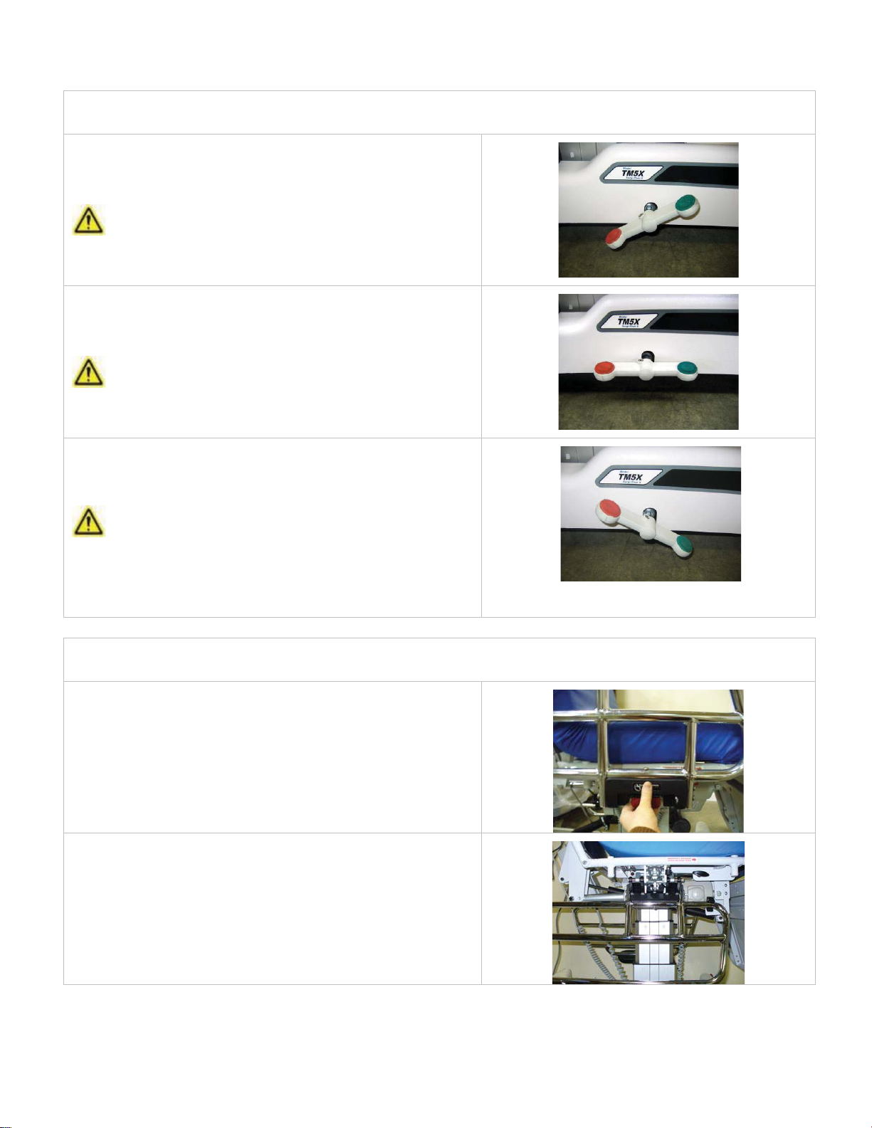
CASTER BRAKE OPERATION
BRAKE MODE
Activate braking system by pressing down on red end of either
brake pedal located at base of chair.
This mode prevents all four casters from swiveling and all
wheels from spinning.
NEUTRAL MODE
Activate neutral mode by placing either brake pedal into a
horizontal orientation.
This mode allows all four casters to swivel and all wheels to
spin freely.
STEER MODE
Activate steer-locking system by pressing down on green end
of either brake pedal located at base of chair.
This mode locks caster (near patient’s right foot) parallel to
base, but allows this wheel to spin. Other three casters swivel,
and wheels spin freely.
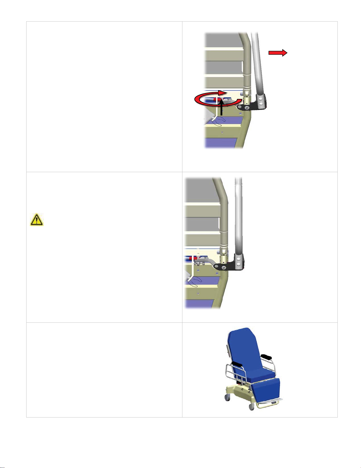
SIDE RAIL OPERATION
LOWERING SIDE RAIL
Grasp top of side rail and push inward slightly, while pulling out
red rail release tab. Once released, lower rail.
STOWING SIDE RAIL
To stow side rail, lower rail into “down” position below seat (or
back section depending on rail location). Push side rail until it
fully engages retainer clip.
Document No.: OM TMM5-X SERIES
Revision: T
Page 11 of 26

RAISING SIDE RAIL
Lift side rail until it is in “up” position.
xRed rail release tab will engage (lock) automatically.
xEnsure side rail is secure by pulling on rail after it is raised.
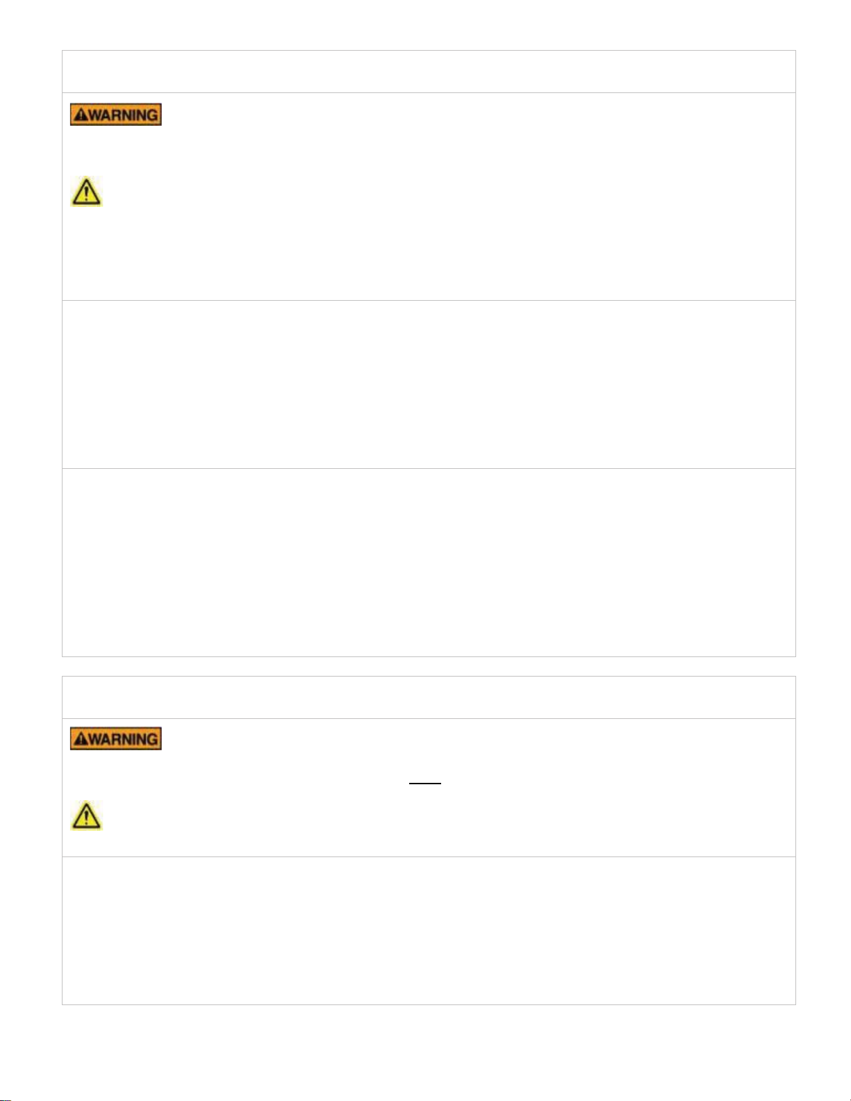
ADJUSTING SIDE RAIL ANGLE
Remove cushion and seat pan by removing four pan
head screws.
NOTICE
Do not discard seat pan, pan head screws, or additional
hardware removed during this step. Parts will be reused
after adjustment.
Loosen top jam nut.
To move inward, rotate bottom jam nut as shown.
Document No.: OM TMM5-X SERIES
Revision: T
Page 12 of 26
To move outward, rotate bottom jam nut as shown.
Once aligned, tighten top jam nut.
NOTICE
1) You do not need to hold bottom nut to tighten
top. Once aligned, top nut is tightening nut.
2) When adjusting, ensure bottom jam nut is
contacting seat frame.
3) Ball joint head angle does not matter.
4) Prior to adjustment, pull outward on side rail in
order for system to settle.
5) Ensure top jam nut engages at least two full
threads.
Do not over tighten top jam nut (there is no need).
Reattach seat pan and cushion.
Document No.: OM TMM5-X SERIES
Revision: T
Page 13 of 26

PENDANT (CONTROLLER)
PENDANT IS NOT INTENDED FOR PATIENT’S USE
To prevent damage, pendant can be stored at various locations
on the chair when not in use.
ENSURE AREA IS CLEAR OF OBSTRUCTIONS PRIOR TO
PENDANT USE
To prevent property damage or injury to patient, survey area for
possible obstructions prior to pendant use.
BACK SECTION ADJUSTMENT
First row of pendant buttons controls angle of back section.
xPress left button to raise chair’s back.
xPress right button to lower chair’s back.
LEG SECTION ADJUSTMENT
Second row of pendant buttons controls angle of leg section.
xPress left button to raise chair’s leg section.
xPress right button to lower chair’s leg section.
SEAT HEIGHT ADJUSTMENT
Third row of pendant buttons controls height of seat section.
xPress left button to raise chair’s seat.
xPress right button to lower chair’s seat.
SIMULTANEOUS LEG AND BACK SECTION
(AUTO CONTOUR) OPERATION
Fourth row of pendant buttons controls simultaneous actuation
of leg and back sections.
xPress left button to raise chair’s leg section and lower
chair’s back, resulting in stretcher configuration.
xPress right button to lower chair’s leg section and raise
chair’s back, resulting in chair configuration.
SEAT TILT / TRENDELENBURG ADJUSTMENT
Fifth row of pendant buttons controls the seat section
incline/recline or Trendelenburg / reverse Trendelenburg
position depending on chair / stretcherPress left button to raise
front of seat section (Trendelenburg in Stretcher position).
xPress right button to lower front of seat section
(Reverse Trendelenburg in Stretcher position).
Document No.: OM TMM5-X SERIES
Revision: T
Page 14 of 26
PATIENT INGRESS / EGRESS
PATIENT SHOULD NEVER BE PERMITTED TO ENTER / EXIT FROM ENDS OF STRETCHER-
CHAIR WHEN IN AN UPRIGHT, PARTIALLY, OR TOTALLY RECLINED POSITION. EXCESSIVE WEIGHT ON
ENDS COULD CAUSE CHAIR TO TILT, RESULTING IN POSSIBLE PATIENT INJURY.
xFollow these instructions for safe and proper patient ingress (entry onto chair) and egress (exit from chair).
xPatient ingress / egress should always be made with chair in upright-chair position.
xPatient must enter / exit from side of chair with their body weight centered over SEAT section.
xSee PATIENT TRANSFER section for instruction on transferring patient from one horizontal surface to another.
PATIENT INGRESS (ENTRY)
1. Depress RED caster brake pedal to lock caster wheels.
2. Adjust chair to lowest height and into upright-chair position.
3. Lower one side rail of seat section.
4. If back section rails are present, remove / lower back section rail of same side.
5. Position patient (facing away from chair) at SEAT section.
6. WITH PATIENT ENTERING FROM SIDE OF CHAIR, assist patient while they sit down on SEAT section.
7. Once patient is fully seated, assist them in rotating their body in-line with chair into a seated position.
PATIENT EGRESS (EXIT)
1. Depress RED caster brake pedal to lock caster wheels.
2. Adjust chair to lowest height and into upright-chair position.
3. Lower one side rail of seat section.
4. If back section rails are present, remove / lower back section rail of same side.
5. Ensure patient’s body weight is centered on SEAT section.
6. WITH PATIENT EXITING TO SIDE OF CHAIR, assist patient in rotating their body by placing their legs over
one side of chair.
7. Assist patient into standing position from seated position.
PATIENT TRANSFER
PATIENT’S BODY WEIGHT SHOULD NEVER BE SHIFTED TOWARDS EITHER END OF CHAIR
WHEN IN A PARTIALLY, OR TOTALLY, RECLINED POSITION. SERIOUS PATIENT INJURY MAY OCCUR.
ALL PATIENT TRANSFERS MUST BE MADE FROM SIDE OF CHAIR, NOT CHAIR ENDS.
Follow these instructions for safe and proper patient transfer between chair (in stretcher orientation) and
another horizontal surface.
1. Position back, seat, and leg sections into horizontal orientation. (Press Auto Contour button.)
2. Lower / remove all side rails from transfer side of chair.
3. Position chair as close as possible to other surface.
4. Match chair (stretcher) height to height of bed or other horizontal surface.
5. Depress RED caster brake pedal to lock caster wheels.
6. Slide patient from one surface to other, following your facility’s standard practices / policies for lateral
patient transfers.
Document No.: OM TMM5-X SERIES
Revision: T
Page 15 of 26
HEAD EXTENSION REMOVAL / INSTALLATION
Do not push chair using head extension.
REMOVAL
Rotate black knob counterclockwise until head extension is free
to slide. Pull extension out of mounting socket.
INSTALLATION
Slide extension into mounting socket. Tighten black knob to
secure extension.
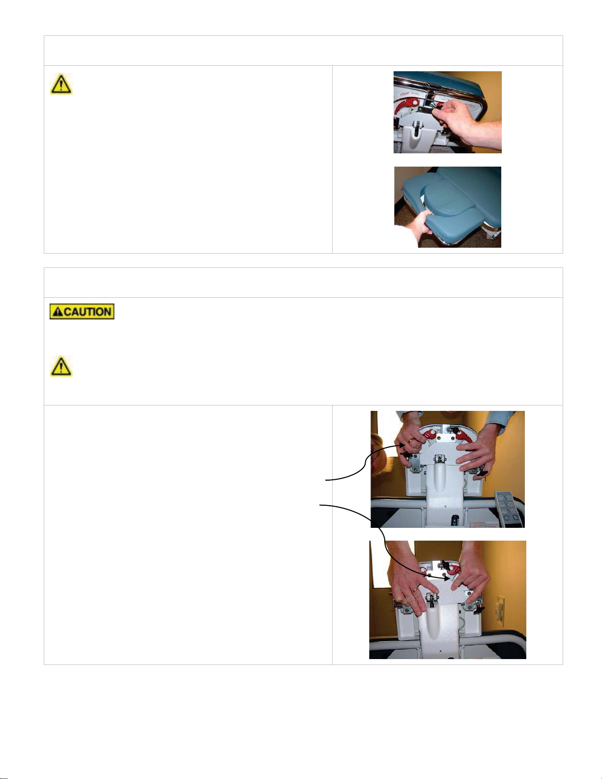
HEADREST OPERATION
TO ENSURE PATIENT SAFETY WHEN CHAIR IS OCCUPIED, BE PREPARED TO SUPPORT HEADREST
DURING ADJUSTMENT.
During adjustment, use at least one hand to support headrest while other hand operates one of two red handles.
For best control, operate one handle at a time, while supporting headrest with both hands.
HEADREST ADJUSTMENT
xPosition yourself directly behind headrest.
xSupport headrest with both hands.
xArticulate headrest angle by squeezing left red handle.
Once correct angle is achieved, release red handle to
lock.
xAdjust headrest height by squeezing right red handle.
Once correct height is achieved, release red handle to
lock.
Document No.: OM TMM5-X SERIES
Revision: T
Page 16 of 26
SUPPORT LEG OPERATION
xUsing support leg increases stability of back section and headrest.
xWhen support leg is in use, do not lower chair height or back section to prevent chair damage.
xStow support leg in proper mounting clip when not in use.
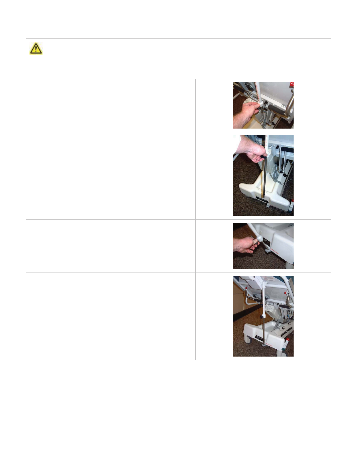
DEPLOY SUPPORT LEG
With back section in upright position, firmly pull support leg
from mounting clip.
LENGTHEN INNER SHAFT
While holding inner shaft of support leg, rotate knob
counterclockwise allowing shaft to slide.
POSITION INNER SHAFT
Recline back section until inner shaft engages support bracket
located near center back of base section.
SET LENGTH
Adjust chair height and back articulation until proper position is
achieved. Once achieved, rotate knob clockwise until tight to
set length of support leg.
Document No.: OM TMM5-X SERIES
Revision: T
Page 17 of 26
OPTIONS
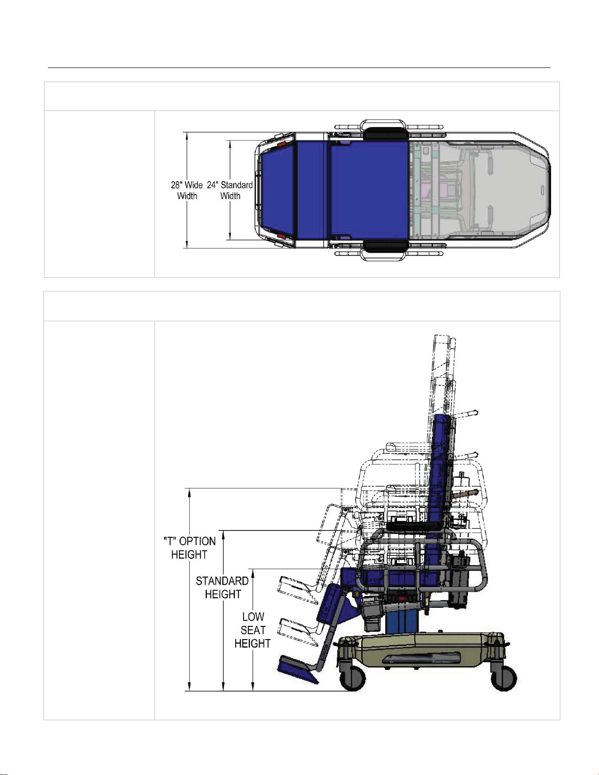
“W” OPTION: WIDE WIDTH
For “W” option, patient
surface width is 28”.
Standard width is 24”.
“T” OPTION: TALL HEIGHT
For “T” option, chair
height travel is 16”.
Standard travel is 8”.
Document No.: OM TMM5-X SERIES
Revision: T
Page 18 of 26

“L” OPTION: LOW HEIGHT
For “L” option, chair
height is 23.5”
Standard height is 25”.
Chair height travel is
the same as Standard
and “T” Option.
To prevent chair
damage, ensure
ground clearance is at
least 1.75” when
driving chair up a ramp
or over a bump.
“F” OPTION: FOLDING FOOTREST
WHEN POSITIONING FOOTREST,
BE AWARE OF PINCH POINTS
To stow footrest, place both hands on
red handles and lift.
For patient comfort, stow footrest prior
to articulating chair into supine
(stretcher) position.
EXTENDED FOOTREST STOWED FOOTREST
Document No.: OM TMM5-X SERIES
Revision: T
Page 19 of 26
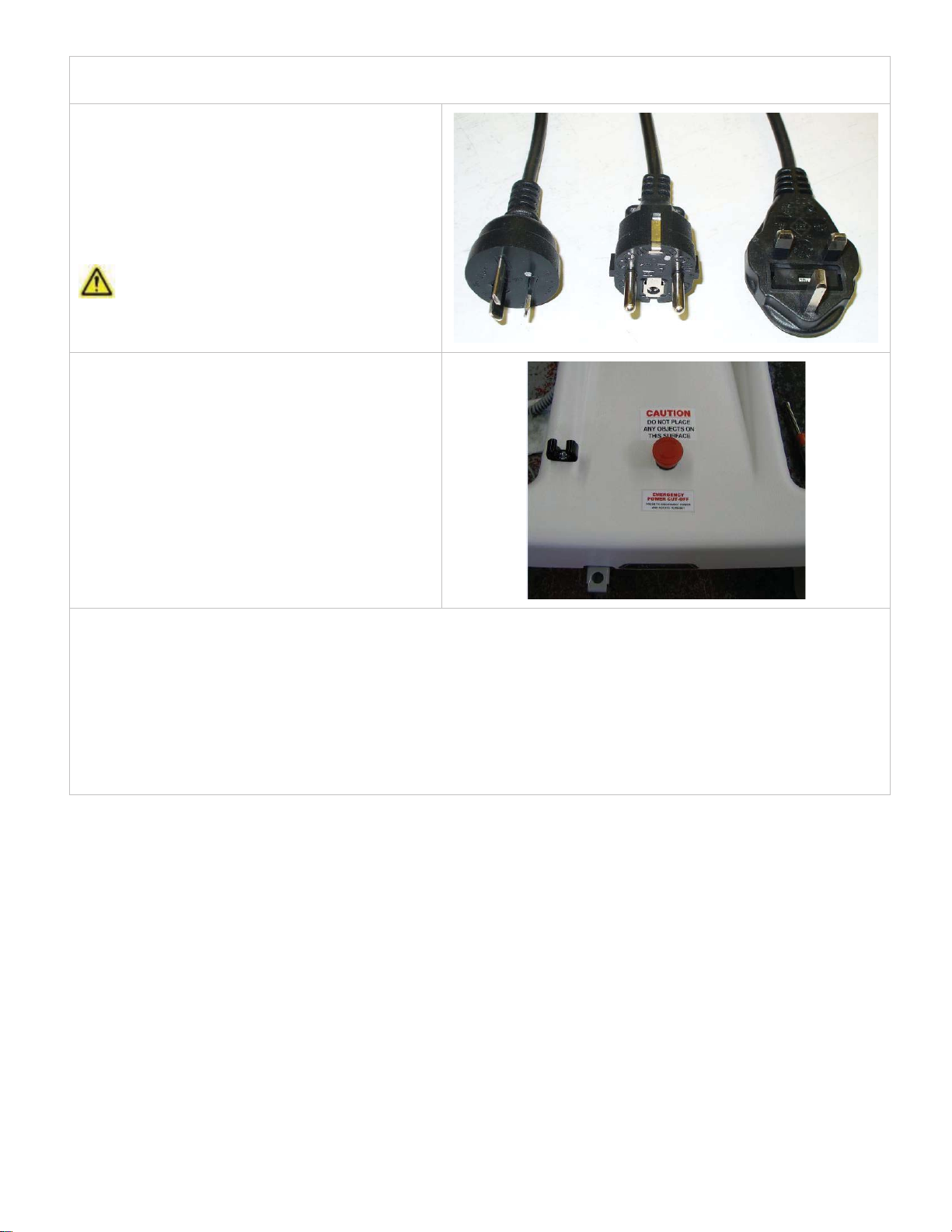
“E” OPTION: EXPORT
“E” option designates chair was shipped with power
cord specific to receiving country.
“A” option power cord is directly attached to chair.
“B” option power cord is attached to battery charger
(# TMA57-15).
Power cords depicted in image may not match
power cord shipped with your chair.
OPERATING RED POWER SHUTOFF
BUTTON
xWhen button is pressed, following items are
disabled:
oChair Articulation
oSeat Height Adjustment
xTo reset red button, twist clockwise until button
pops back up.
EMERGENCY SHUTOFF PROCEDURE
During an emergency shutoff due to erratic performance, follow these steps:
1. Immediately press the RED emergency shutoff button on back of base cover to disable all electrical components.
2. Using proper safe patient handling procedures, assist patient with egress from chair.
3. Call TMM Service Department to report incident and to initiate investigation.
4. Discontinue chair use until cleared by TMM Service Department.
Document No.: OM TMM5-X SERIES
Revision: T
Page 20 of 26
Table of contents
Popular Medical Equipment manuals by other brands


Radian
Radian HEART GUARDIAN HR-503HEART GUARDIAN HR-503 A user manual

Siemens
Siemens SIREMOBIL Iso-C Service instructions

Verathon
Verathon BladderScan BVI 3000 Service manual

Kegel8
Kegel8 Mother Nurture Operator's manual

Mindray
Mindray Rosebud Accutorr V user manual

Blatchford
Blatchford Mini BladeXT user guide