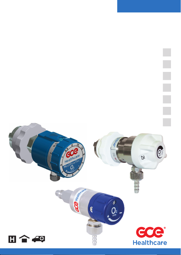
GCE MediFlowTec MEDIFLOW 2 User manual

GCE HEALTHCARE
MediFlowTec™, MEDIFLOW® II,
MEDIFLOW +
EN
FLOWMETERING DEVICES
FLOW SELECTOR; INSTRUCTION FOR USE
DISPOSITIVOS PARA MEDIR EL CAUDAL
CAUDALÍMETRO; INSTRUCCIONES DE USO
FLUSSOMETRI
MISWURATORE DI FLUSSO; ISTRUZIONI D´USO
FLUXÓMETROS; INSTRUÇÕES DE UTILIZAÇÃO
DEBITMETRES; NOTICE D´INSTRUCTIONS
FLOWMETER; BEDIENUNGSANLEITUNG
PRŮTOKOMĚRY; NÁVOD K POUŽITÍ
ES
IT
PT
FR
DE
CS


3/72
EN
1. FOREWORD
GCE Flow selectors are medical devices classified as class IIa according to
the Medical Device Directive 93/42/EEC.
The Compliance with essential requirements of 93/42/EEC Medical Device
Directive is based upon 15002 standard.
2. INTENDED USE
Mediflow are devices intended for the administration of the following med-
ical gases in the treatment and care of patients:
• oxygen O2
• medical air AIR
• nitrous oxide N2O
The product is not intended to be use with air or nitrogen for driving
surgical tool.
This flow selector is intended to be fitted to medical gas pipeline system
terminal units in hospital or ambulance car or to quick connector outlet of
medical regulator, with nominal pressures up to 5 bar.
Using variants with maximum flow 50 l/min is necessary to be more care-
ful and outlet of the flow selector MUST NOT be connected directly to the
patient, for example via cannula.
The set value on the flow selector does NOT indicate real the actual flow
of medical gas – the dierence can be caused by dierent (missing) inlet
pressure or any fault on outlet hose (blocked, fold…)
3. OPERATIONAL, TRANSPORT AND STORAGE
SAFETY REQUIREMENTS
Keep away the product and its associated equipment from:
• heat sources (fire, cigarettes, …),
• flammable materials,
• oil or grease
• water
• dust
The product and its associated equipment must be prevented from
falling over.
ENGLISH
INSTRUCTION FOR USE:
MediFlowTec™, MEDIFLOW® II, MEDIFLOW +

4/72
EN
Use only the product and its associated equipment in well vented area.
Always maintain oxygen cleanliness standards.
Before initial use the product should be kept in its original packaging. GCE
recommends use of the original packaging (including internal sealing bag
and caps) if the product is withdraw from operation (for transport, storage).
Statutory laws, rules and regulations for medical gases, accident preven-
tion and environmental protection must be observed.
OPERATING CONDITIONS STORAGE AND
TRANSPORT CONDITIONS
-20/+60 °C -30/+60 °C
10/100% 10/100%
600/1200 mbar 600/1200 mbar
In case of storage at a temperature below -20 °C, do not operate the
flow selector until it has been allowed to increase its temperature to a
minimum of -20 °C.
4. PERSONNEL INSTRUCTIONS
The Medical Devices Directive 93/42/EEC states that product provider
must ensure that all personnel handling the product are provided with the
operating instructions & performance data.
Do not use the product without properly familiarization of the product
and its safe operation as defined in this Instruction for use. Ensure user
is aware of particular information and knowledge required for the gas
in use.

5/72
EN
5. PRODUCT DESCRIPTION
Gas from the medical gas pipeline system is entering through the inlet
connector (A). There are two basic versions: 1 – inlet connector is directly
mounted on the flow selector, 2 – connection to the rail, including hose
and inlet connector. Flow is then adjusted to the requested value by turn-
ing handwheel (B). The adjusted flow is visible in the window of the hand-
wheel /on the pointer (C). Gas is delivered to the user through the flow
outlet user connection (D).
B
C
A
DD
A
B
C
A. INLET QUICK CONNECTOR
The flow selector is fitted to the medical gas pipeline system terminal unit
or to medical regulator by a gas specific male probe.
B. HANDWHEEL
Requested gas flow can be adjusted by turning the handwheel to set the
required value in the viewing window / pointer (calibrated in l/min). By the
handwheel is possible to close the gas flow – adjusting value “0”.
C. READING WINDOW
Adjusted value of the gas flow is visible in reading window / on the top
side of the pointer.
D. USER OUTLET
The “flow outlet” user connection is usually with connection for hose (hose
nipple) or threaded (for humidifier).
This outlet is for supplying a gas flow (l/min) atmospheric pressure directly
to a patient, e.g. through a cannula or a facemask.
A
D
C
B

6/72
EN
The flow outlet shall not be used for driving any medical device.
Note also that products colour (especially handwheel) might not follow any
gas colour coding.
6. OPERATIONS
6.1. BEFORE USE
6.1.1. VISUAL INSPECTION BEFORE FITTING
• Check if there is visible external damage of the flow selector (including
product labels and marking). If it shows signs of external damages, re-
move it from service and identify its status.
• Visually check if the product is contaminated; if needed, for the flow
selector, use the cleaning procedure detailed in this instruction for use.
• Ensure the handwheel is set on “0” position (turning anticlockwise).
• Ensure that connected hose nipple or humidifier to the outlet has correct
dimensions.
The flow selector is dedicated only for use with the gas specified on its
labelling. Never try to use for another gas.
6.1.2. FITTING TO MEDICAL GAS PIPELINE SYSTEM TERMINAL UNITS
The flow selector shall be connected in accordance with suitable type of
terminal unit or with a regulator with an appropriate quick connector, see
appendix nr.2.
6.1.3. FUNCTIONAL TEST
• Check that there is a gas flow at each setting higher than “0” set by the
handwheel (for instance, by listening of the sound of gas flow or check-
ing presence of bubbles in a humidifier).
• Set the handwheel back to the close position – value “0”.
If any leakage is detected, use the procedure in chapter 6.3 and return
the product to GCE for service.
6.2. CONNECTION & USE OF OUTLET
6.2.1. LIST OF RECOGNIZED ACCESSORIES
To be connected to the flow outlet:
• Humidifier, breathing mask or cannula.
Before connecting any accessory or medical device to the flow selector,
always check that it is fully compatible with the product connection fea-
tures & the product performances and there is no negative influence to
outlet parameters of the flow selector.
6.2.2. FLOW OUTLET CONNECTION
When connecting any accessory to the flow outlet make sure that it is not
connected to the patient before operating the product.

7/72
EN
• Ensure the hose/humidifier is compatible with the flow outlet feature.
• Push the hose onto the flow selector flow outlet/screw onto the humidi-
fier.
• Ensure the hose/humidifier is well engages.
6.2.3. FLOW SETTING
• Connect the flow selector to the source of medical gas.
• Set requested medical gas flow by the handwheel.
Do not try to apply an excessive torque on the flow control knob when it
stops on the maximum flow position or in zero position.
Always ensure that the flow control knob has engaged and not placed
between two settings otherwise the flow selector will not deliver the cor-
rect flow of medical gas.
During use ensure that connected hose is not mechanically damaged,
throttled or broken, which would reduces or breaks supply of gas to the
patient.
The medical gas flow rate must be prescribed and administered by a clini-
cally trained user.
Fluctuating inlet pressure and ambient temperature can have influence
on accuracy of flow measurement.
6.3. AFTER USE
• Before disconnecting flow selector from the medical pipe line system
terminal unit or medical regulator, set the handwheel on close position -
value “0”.
• Remove connected accessories from user outlet.
• Disconnect flow selector from user outlet.
7. CLEANING
Remove general contamination with a soft cloth damped in oil free oxygen
compatible soap water & rinse with clean water.
Disinfections can be carried out with an alcohol-based solution (spray or
wipes).
If other cleaning solutions are used, check that they are not abrasive and
that they are compatible the product materials (including labels) and gas.
Do not use cleaning solutions containing ammonia!
Do not immerse in water or any liquid.
Do not expose to high temperature (such as autoclave).
To apply the cleaning solution, do not spray it, as the spray may enter the
inner parts of product and cause contamination or damage.
Do not use pressure water as it could damage or contaminate the
product.

8/72
EN
Do not use the product under any circumstances of the inner parts of
the product have been contaminated. It must be withdrawn from service.
8. MAINTENANCE
8.1. PRODUCT LIFE TIME
Depending on the date of production you can find on the product the
marking in one of two versions are easy to see and easy to dierentiate.
8.1.1. MARKING PRIOR TO IMPLEMENTING UDI CODING
Form of nine digits serial number stamped on the product is following:
YYMMXXXXX
YY: year of production
MM: month of production
XXXXX : sequence number
Example: serial number 190300521 shows the product produced in March
2019, with sequence number 521.
An additional 2D code (for internal usage in production process in GCE) is
also part of product’s marking .
8.1.2. MARKING AFTER UDI CODING IMPLEMENTATION
There are 3 marked identifiers on the medical device surface:
14 numbers with prefix (01): GTIN - Global Trade Identification Number
(identification of the selector type)
9 numbers with prexix (21): serial number in format YYMMXXXXX
6 numbers with prefix (17): the end of the product´s life time in format
YYMMDD
Example: marking number (17) 290227 shows the medical device with end
of lite time on 27th of February 2029.
As the integral part of UDI marking is a 2D code, which consists of the
same data. The batch number is included in the 2D code (prefixed (10) )
and it is for manufacturer use.
8.1.3. PRODUCT LIFE TIME AND WASTE MANAGEMENT
Maximum life time of the product is 10 years. At the end of the product’s life
time, the product must be withdrawn from service (max.10 years).
The owner of the device shall prevent the reuse of the product and han-
dle the product in compliance with “Directive of European Parliament and
Council 2006/12/ES of 5th April 2006 on waste“. In accordance to Article
33 of REACH GCE, s.r.o. as responsible manufacturer shall inform all cus-
tomers if materials containing 0.1% or more of substances included in the
list of Substance of Very High Concern (SVHC). The most commonly used
brass alloys used for bodies and other brass components contain 2-3% of
lead (Pb), EC no. 231-468-6, CAS no. 7439-92-1. The lead will not be re-
leased to the gas or surrounding environment during normal use.

9/72
EN
After end of life the product shall be scrapped by an authorized metal re-
cycler to ensure ecient material handling with minimal impact to environ-
ment and health. To date we have no information that indicates that other
materials containing SVHC of concentrations exceeding 0.1% are included
in any GCE product.
8.2. SERVICE, REPAIRS AND MAINTENANCE
8.2.1. SERVICE
GCE recommends that a product periodic inspection is undertaken at least
once a year to do leakage test and check proper functionality of the flow
selector.
8.2.2. LEAKAGE TEST
• After connection to medical gas pipeline system terminal unit or to medi-
cal regulator, visually check possible leakages:
LEAKAGE TEST OF THE FLOW SELECTOR FOR FLOW ADJUSTMENT:
1. Adjust by handwheel the value „0“. When closing don´t use excessive
torque.
2. Connect the flow outlet and hose nipple with a hose, the end of the
hose immerse into a jar filled with water.
3. Connect the flow selector to the source of compressed air max. 5 Bar.
4. The test: leave the flow selector 1min under pressure. Number of
bubbles shall not be higher than 3 bubbles per 1 min.
5. When test ready, disconnect the flow selector from the source of
compressed air.
EXTERNAL LEAKAGE TEST:
1. Adjust by handwheel of the flow selector the value „0“. When closing
don´t use excessive torque.
2. Close the outlet connection of the flow selector using a plug, the plug
has to have the same thread as the outlet connector of the flow selector
or, in the case the hose nipple used, use the hose with blind plug.
3. Connect the flow selector to the source of compressed air max. 5 Bar.
4. Adjust by handwheel of the flow selector the maximal value. When
opening don´t use excessive torque.
5. Possible leakage you will detect by application of soap water on
product joins.
6. After test disconnect the flow selector from the source of compressed
air, remove the plug from outlet connection and carefully clean the
surface of the flow selector, see chapter 7 (cleaning).
If any leakage is detected, use the procedure in chapter 6.3 and return
the pro-duct to GCE for service.
The product shall not be disassembled or repaired when connected to
the source of the pressure.

10/72
EN
REPAIRS ACTIVITIES COVER THE REPLACEMENT OF THE FOLLOWING
DAMAGED OR MISSING COMPONENTS:
• quick connector (probe),
• flow head (valid only for MFII and MF+)
• plastic cover and handwheel (valid only for MFT)
The repairs shall be carried out by a GCE authorised person only.
Any product sent back to a GCE authorised person for maintenance shall
be properly packaged. The purpose of the maintenance has to be clearly
specified (repair, maintenance). For product to be repaired a short descrip-
tion of fault and any reference to a claim number might be helpful.
Some repair activities concerning to the replacement of the damaged or
missing components can be carried out by the owner of the product. The
following parts can be replaced only:
• Caps,
• Stickers,
• Hose nipple (including o-ring),
To use suitable component, contact our service organization.
All labels on the equipment must be kept in good, legible condition by the
owner and the user during the entire product life time.
All seals and o-rings must be kept in dry, dark and clean environment by
the owner and the user during the entire product life time.
Use only original GCE components!
9. GLOSSARY
Consult instruction for
use
Suitable for Home care
use
Caution Suitable for Hospital
care use
Keep away from heat and
flammable material
Suitable for Emergency
care use
Keep away from oil and
grease SN Serial number
Humidity limit REF Catalogue number
Temperature limit LOT Batch code
Keep dry Fragile, handle with care

11/72
EN
Date of manufacture Manufacturer
Use by date P1Inlet pressure
Inlet parameter Outlet parameter
10. WARRANTY
The Standard Warranty period is two years from date of receipt by the GCE
Customer (or if this is not known 2 years from time of the product manufac-
ture shown on the product).
The standard warranty is only valid for products handled according to
Instruction for use (IFU) and general industry good practice and stand-
ards.
APPENDIX:
Nr 2 - Quick coupling feature and connecting/disconnecting procedure
MANUFACTURER:
GCE, s.r.o. Tel: +420 569 661 111
Zizkova 381 Fax: +420 569 661 602
583 01 Chotebor http://www.gcegroup.com
Czech Republic © GCE, s.r.o.

12/72
ES
1. INTRODUCCIÓN
Los caudalímetros GCE son dispositivos medicinales clasificados como
clase IIa, conforme a la directiva sobre los dispositivos medicinales
93/42/CEE.
La conformidad con los requerimientos esenciales de la directiva 93/42/
CEE es a base de la norma 15002.
2. USO PREVISTO
Mediflow son dispositivos apto para regular el flujo destinado a la aplica-
ción de los siguientes gases medicinales al curar y cuidar los pacientes:
• oxígeno O2
• aire medicinal AIR
• gas hilarante (óxido nitroso) N2O
El producto no es apto para el uso con gases para accionar las herramien-
tas quirúrgicas.
El caudalímetro está destinado para una conexión a equipos terminales
(tomas de pared) de redes centrales para gas medicinal en los hospitales,
o a la toma rápida de la válvula reguladora medicinal, con unas presiones
nominales de máx. 5 Bar.
Respecto a las variantes con el caudal máximo de 50 l/min. hay que tener
mayor cuidado y la salida del caudalímetro NO DEBE estar directamente
conectada a las vías respiratorias del paciente, por ejemplo por la cánula
nasal.
El valor establecido en el selector de flujo NO indica el flujo real actual
de gases medicinales – la diferencia puede ser causada por diferente
presión de entrada (o presión de entrada ausente) o cualquier falla en la
manguera de salida (manguera bloqueada, doblada…).
ESPAÑOL
INSTRUCCIONES DE USO:
MediFlowTec™, MEDIFLOW® II, MEDIFLOW +

13/72
ES
3. EXIGENCIAS DE SEGURIDAD RELATIVAS AL
SERVICIO, TRANSPORTE Y ALMACENAMIENTO
Mantenga el producto y sus accesorios alejados de :
• fuentes de calor (fuego, cigarrillos, …),
• materiales inflamables,
• aceite o grasa, (tome mayores precauciones al usar cremas para las
manos)
• agua,
• polvo.
El producto y sus accesorios deben estar protegidos contra el volqueo.
Use el producto y sus accesorios únicamente en áreas bien ventiladas.
Respete siempre las normas de pureza del oxígeno.
Antes de su primer aplicación debe estar el producto en su embalaje ori-
ginal. En caso de ser retirado el producto fuera del servicio (a causa del
transporte, del almacenaje), GCE recomienda usar el embalaje original (in-
cluso los materiales para llenar el interior).
Es necesario observar las leyes nacionales, los reglamentos y regulacio-
nes para gases medicinales, seguridad de trabajo y protección del medio
ambiente.
RÉGIMEN DE
FUNCIONAMIENTO
CONDICIONES DE ALMACENA
JE Y TRANSPORTE
-20/+60 °C -30/+60 °C
10/100% 10/100%
600/1200 mbar 600/1200 mbar
Caso de almacenar la válvula a una temperatura bajo -20°C, no utilice la
válvula hasta que su temperatura alcance por lo menos -20°C.
4. INSTRUCCIONES DE PERSONAL
Según la directiva 93/42/CEE para dispositivos médicos, el propietario del
producto deberá asegurarse, que todos los usuarios tengan las instruc-
ciones de uso y los datos técnicos.
No utilice el producto sin familiarizarse debidamente con el producto y
su funcionamiento seguro, así como se defi ne en las Instrucciones de
uso. Asegúrese de que el usuario tenga la información adecuada y el
conocimiento requerido para el gas utilizado.

14/72
ES
5. DESCRIPCIÓN DEL PRODUCTO
El gas de la red central de gas medicinal pasa por el conector rápido de
entrada (A). Existen dos variantes básicas: 1 – el conector rápido instalado
directamente al caudalímetro, 2 – conexión a la barra, incluso la manguera
con conector rápido. Después está el caudal del gas ajustado al valor de-
seado girando el mando de control (B). El caudal ajustado se indica en la
mirilla del mando de control /en el indicador (C). El gas está suministrado
al usuario mediante el racor de salida (D).
4/68
EN
B
C
A
DD
A
B
C
A
D
C
B
A. CONECTOR RÁPIDO DE ENTRADA
El caudalímetro se conecta a la unidad extrema de la red central de gas
medicinal, o a la válvula de regulación medicinal mediante el conector rá-
pido para el gas respectivo.
B. MANDO DE CONTROL
Mediante el mando se puede ajustar el valor deseado del caudal de gas
girando el volante para establecer el valor requerido en el agujero de in-
dicación / indicador (calibrado en l/min). Mediante el mando de control es
posible cerrar el caudal del gas – ajuste a la posición 0.
C. MIRILLA DE LECTURA
En la mirilla de lectura se puede leer el valor ajustado del caudal de gas/
en el indicador en la parte delantera.
D. RACOR DE SALIDA
El racor de salida, generalmente con la conexión para manguera (espiga
porta-manguera) o con una rosca (para el frasco humedecedor).

15/72
ES
Esta salida sirve para administrar el caudal de gas medicinal (l/min.) con
presión atmosférica directamente al paciente, por ejemplo mediante una
cánula o una mascarilla.
El racor de salida no se debe usar para accionar dispositivos medicinales.
Nota: Los colores del producto (especialmente del mando de control de
caudal) puede que no correspondan a ninguna codificación de color de
gases.
6. SERVICIO
6.1. ANTES DEL USO
6.1.1. CONTROL VISUAL ANTES DE LA INSTALACIÓN
• Verifique que no haya deterioraciones exteriores visibles en el caudalí-
metro (incluso en las etiquetas y marcaciones). Si el dispositivo manifies-
ta signos de deterioración exterior, póngalo fuera de servicio indicando
su estado.
• Verifique visualmente que el producto no está sucio; emplear en caso
necesario el procedimiento de limpieza según las instrucciones mencio-
nadas en estas instrucciones de uso.
• Verifique que el caudalímetro está ajustado a la posición „0“ (girando
contra el sentido de las manillas de reloj).
• Verifique que ha conectado al racor de salida la espiga porta manguera
o el frasco humedecedor de dimensiones adecuadas.
El caudalímetro está destinado para ser usado solamente con el gas indi-
cado sobre su etiqueta. Jamás intentar utilizar con otro gas.
6.1.2. CONEXIÓN A LAS UNIDADES TERMINALES DE LAS REDES
CENTRALES DEL GAS MEDICINAL
• Conecte el caudalímetro conforme al tipo correspondiente de la unidad
terminal o con regulador con conector rápido apropiado, según el Ane-
xo No. 2
6.1.3. PRUEBA FUNCIONAL
• Verifique que si al ajustar cualquier valor mayor que „0“ mediante el
mando de control giratorio, existe el caudal del gas (por ejemplo me-
diante el sonido o la revisión de presencia de burbujas en el frasco hu-
medecedor).
• Vuelva el mando de control de caudal a la posición cerrada – valor „0“.
6.2. CONEXIÓN Y USO DEL RACOR DE SALIDA
6.2.1. LISTA DE ACCESORIOS AUTORIZADOS
Para la conexión al racor de salida:
• Frasco humedecedor, mascarillas respiradoras y cánulas.

16/72
ES
Antes de conectar al caudalímetro cualquier tipo de accesorios o de pro-
ducto sanitario verifique que éstos sean plenamente compatibles con los
elementos y parámetros de potencia del caudalímetro, y que no sucede
la influencia negativa de los parámetros de salida del caudalímetro.
6.2.2. CONEXIÓN AL RACOR DE SALIDA
Antes de conectar cualquier tipo de accesorio al racor de salida verifi-
que que el paciente no esté unido antes de iniciar el funcionamiento del
dispositivo.
• Verifique que la manguera/frasco humedecedor son compatibles con
el racor de salida.
• Verifique que la manguera/frasco humedecedor están en posición co-
rrecta.
6.2.3. AJUSTE DEL CAUDAL
• Conecte el caudalímetro al gas medicinal bajo presión.
• Ajuste mediante el mando de control giratorio el caudal deseado del
gas medicinal.
Caso de que el mando de control giratorio está en las posiciones topes,
no trate de aplicar una fuerza excesiva, puede ocurrir una damnificación
irrevocable de la pieza.
Asegúrese siempre de que la perilla de control de flujo ha entrado en
la posición deseada y no esté colocada entre dos configuraciones; de
lo contrario, el selector de flujo no entregará el caudal correcto de gas
médico.
Durante la utilización cuide que no suceda un daño mecánico, estrangu-
lación o rotura de la manguera lo que podría reducir o cortar el suministro
de gas al paciente.
La tasa del flujo de gas médico debe ser prescrita y administrada por un
usuario clínicamente capacitado.
La presión de entrada y temperatura ambiental oscilantes pueden influir
la precisión de la medición de caudal.
6.3. DESPUÉS DE CADA USO
• Vuelva a poner el mando de control giratorio a la posición cerrada – va-
lor „0“, antes de desconectar el caudalímetro de la unidad extrema de la
red central de gas medicinal, o de la válvula medicinal de reducción.
• Desconecte los accesorios conectados del racor de salida del caudalí-
metro.
• Desconecte el caudalímetro del racor de salida.

17/72
ES
7. LIMPIEZA
Limpie las suciedades con un trapo fino empapado en agua con jabón
compatible con oxígeno y sin aceite y lávelo con agua limpia. Los deter-
gentes utilizados deben cumplir las normas relacionadas con la limpieza
de los equipos a oxígeno. La desinfección se puede realizar con la solu-
ción a base de alcohol (rociando o limpiando con un paño).
Si emplea otras soluciones de detergentes, verifique que no sean abrasi-
vas y que sean compatibles con los materiales del producto (incluso las
placas) y el gas respectivo.
No use soluciones de detergentes que contengan amoníaco!
No sumerja el dispositivo en agua o cualquier otro tipo de líquido.
No exponga el dispositivo bajo altas temperaturas (por ejemplo en un
autoclave).
Para aplicar la solución de limpieza, no la pulverice, ya que puede entrar
en las partes internas del producto y causar contaminación o daños.
No utilice agua a presión, ya que podría dañar o contaminar el producto.
Si las partes internas del producto han sido contaminadas, no continúe
usando el producto bajo cualquier circunstancia. Debe ser retirado del
servicio
8. MANTENIMIENTO
8.1. IDENTIFICACIÓN DE PRODUCTO
Dependiendo de la fecha de producción, puede encontrar en el producto
la marca en una de las dos versiones que son inconfundibles y fáciles de
diferenciar.
8.1.1. MARCADO ANTES DE LA IMPLEMENTACIÓN DE CODIFICACIÓN
UDI
La forma del número de serie de nueve dígitos estampado en el producto
es la siguiente:
AAMMXXXXX
AA: año de producción
MM: mes de producción
XXXXX: número de secuencia
Ejemplo: el número de serie 190300521 muestra el producto producido en
marzo de 2019, con número de secuencia 521.
Código 2D adicional (para uso interno en el proceso de producción en
GCE) también forma parte del marcado del producto.

18/72
ES
8.1.2. MARCADO DESPUÉS DE LA IMPLEMENTACIÓN DE
CODIFICACIÓN UDI
Hay 3 identificadores marcados en la superficie del dispositivo médico:
14 números con prefijo (01): GTIN - Número de identificación comercial glo-
bal (identificación del tipo de selector)
9 números con prefijo (21): número de serie en formato AAMMXXXX
6 números con prefijo (17): el final de la vida útil del producto en formato
AAMMDD
Ejemplo: el número de marcado (17) 290227 muestra que la vida útil del
dispositivo médico es hasta el 27 de febrero de 2029.
Como parte integral del marcado UDI es un código 2D, que consta de los
mismos datos. El número de lote se incluye en el código 2D (con el prefijo
(10)) y es para uso del fabricante.
8.1.3. VIDA ÚTIL Y GESTIÓN DE RESIDUOS
La vida útil máxima de este producto es 10 años a partir de la fecha de
fabricación. Al finalizar la vida útil del producto se debe retirar del servi-
cio. El suministrador del aparato debe evitar la reutilización del producto
y deshacerse de él con arreglo a la “ Directiva 2006/12/ES del Parlamento
Europeo y del Consejo, del 5 de abril del 2006, relativa a los residuos “.
De conformidad con el artículo 33 de REACH, la empresa GCE, s.r.o. como
fabricante responsable, informará a todos los clientes si los materiales
utilizados contengan 0.1% o más de sustancias incluidas en la lista de
Sustancias peligrosas (ECHA – Sustancias extremadamente preocu-
pantes). Las aleaciones de latón más comúnmente utilizadas para cuerpos
y otros componentes de latón, contienen 2-3% de plomo (Pb), CE nro. 231-
468-6, CAS nro. 7439-92-1. El plomo no se liberará al gas ni al entorno
circundante durante el uso normal. Después del fi nal de la vida útil, el
producto debe ser desechado por un centro de reciclaje de metales au-
torizado para garantizar un manejo efi ciente del material con un impacto
mínimo para el medio ambiente y la salud. Hasta la fecha, no tenemos
información que indique que otros materiales que contengan sustancias
extremadamente preocupantes de concentraciones superiores al 0.1% es-
tén incluidos en cualquier producto GCE.
8.2. SERVICIO, REPARACIONES Y MANTENIMIENTO
8.2.1. SERVICIO
GCE recomienda realizar una vez al año las revisiones regulares del pro-
ducto que incluyen la revisión de estanqueidad y del funcionamiento co-
rrecto del caudalímetro.
8.2.2. PRUEBA DE HERMETICIDAD
• Verifique visualmente la hermeticidad después de conectar el cauda-
límetro a la unidad extrema de la red central del gas medicinal, o a la
válvula medicinal reductora:

19/72
ES
REVISIÓN DE HERMETICIDAD DE LA VÁLVULA PARA LA REGULACIÓN
DEL CAUDAL:
1. Ajuste mediante el mando de control del caudalímetro el valor de
caudal a „0“. Durante el cierre no aplique fuerza excesiva
2. Conecte al racor de salida la espiga porta-manguera con una parte de
manguera, y sumerge el extremo de la manguera en el recipiente con
agua
3. Conecte el caudalímetro al aire comprimido de 5 bar máx.
4. El propio ensayo: deje durante 1 minuto el caudalímetro bajo presión. El
número de burbujas no debería superar 3 burbujas por 1 minuto
5. Al terminar el ensayo desconecte el caudalímetro del aire comprimido
REVISIÓN DE LA PERMEABILIDAD EXTERNA:
1. Ajuste el caudalímetro mediante el mando de control giratorio al valor
del caudal „0“. Durante el cierre no aplique fuerza excesiva.
2. Encierre la conexión de salida del caudalímetro mediante la tapa que
debe tener la rosca idéntica con la conexión de salida del caudalímetro.
En el caso de utilizar una boquilla de manguera, use un tapón ciego.
3. Conecte el caudalímetro al aire comprimido de 5 bar máx.
4. Ajuste mediante el mando de control giratorio el valor de caudal al
máximo. Durante la apertura no aplique fuerza excesiva
5. Verifique los escapes eventuales aplicando sobre las uniones el agua
con jabón
6. Después del ensayo desconecte el caudalímetro del aire comprimido,
quite la tapa de la conexión de salida y limpie bien la superficie del
caudalímetro, ver al capítulo 7 (limpieza)
Caso de detectar cualquier permeabilidad, aplique el procedimiento des-
crito en el capítulo 6.3 y devuelve el producto para la reparación.
Nunca desmontar y reparar el producto si está conectado a la alimenta-
ción (a la fuente) de presión.
Las reparaciones incluyen el recambio de los siguientes componentes
averiados o faltantes:
• conector rápido (sonda),
• carga de flujo (válida solo para MFII y MF+)
• cubierta de plástico y volante (válidos solo para MFT)
Las reparaciones las puede realizar solamente la persona autorizada de
GCE.
Cualquier producto enviado a la persona autorizada de GCE para realizar
el mantenimiento debe estar debidamente embalado.
El motivo del mantenimiento debe estar claramente especificado (repa-
ración, mantenimiento total). El producto destinado a la reparación debe
tener una corta explicación y referencia al No. de reclamación.

20/72
ES
Algunas reparaciones relacionadas con el cambio de los componentes
averiados o faltantes las puede realizar el propietario del producto. Sola-
mente los componentes siguientes pueden ser cambiados:
• tapas
• autopegantes
• espiga porta-manguera (incluso el o-anillo).
Para averiguar el componente adecuado contacte nuestra organización
de servicio
Todas las etiquetas sobre el producto deben mantenerse en condiciones
buenas y legibles por el propietario y el usuario durante el tiempo com-
pleto de vida útil del producto.
Todas las empaquetaduras y o-anillos deben mantenerse en un ambiente
seco, ambiente oscuro y limpio por el propietario y usuario durante el
tiempo completo de su vida útil.
¡Utilice únicamente los componentes originales de GCE!
9. GLOSARIO
Consultar instruccionesConsultar instrucciones
de usode uso
Compatible para un usoCompatible para un uso
a domicilioa domicilio
Cuidado (Advertencia)Cuidado (Advertencia) Compatible para un usoCompatible para un uso
en hospitalesen hospitales
Mantener lejos de laMantener lejos de la
fuente de calor y defuente de calor y de
materiales inflamablesmateriales inflamables
Compatible para un usoCompatible para un uso
en emergenciasen emergencias
Mantener lejos delMantener lejos del
aceite y de la grasaaceite y de la grasa SN No. de serie del pro-No. de serie del pro-
ductoducto
Límite superior e inferiorLímite superior e inferior
de humedadde humedad REF Número de articulo delNúmero de articulo del
productoproducto
Límite de temperaturaLímite de temperatura
superior e inferiorsuperior e inferior LOT Número de suministroNúmero de suministro
Mantener secoMantener seco FrágilFrágil
Fecha de fabricaciónFecha de fabricación FabricanteFabricante
Usar hastaUsar hasta PP11Presión de entradaPresión de entrada
This manual suits for next models
1
Table of contents
Languages:
Other GCE Medical Equipment manuals

GCE
GCE MediVital E User manual

GCE
GCE Zen-O lite RS-00600 User manual

GCE
GCE Zen-O RS-00500 User manual

GCE
GCE ECOlite4000 User manual

GCE
GCE MEDIEJECT II User manual

GCE
GCE Medline ECOLITE 4000 User manual

GCE
GCE TERMINAL UNITS MINI User manual

GCE
GCE Zen-O RS-00500 User manual

GCE
GCE Zen-Olite RS-00600 User manual

GCE
GCE S 400 User manual

GCE
GCE Zen-O RS-00500 User manual

GCE
GCE MEDIREG II User manual

GCE
GCE Zen-O RS-00500 User manual

GCE
GCE Zen-O RS-00500 User manual

GCE
GCE Zen-O lite RS-00600 User manual

GCE
GCE OC Series User manual

GCE
GCE MM90 STANDBY User manual

GCE
GCE MEDIMETER User manual

GCE
GCE MediVital User manual

GCE
GCE Zen-O lite RS-00600 User manual