HT-NO-ALPU-GBEP
Installation Instructions
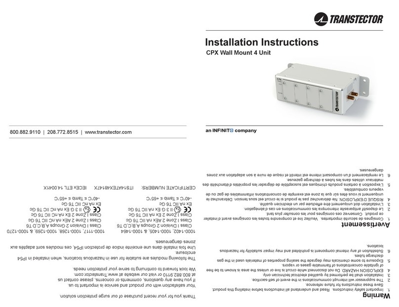
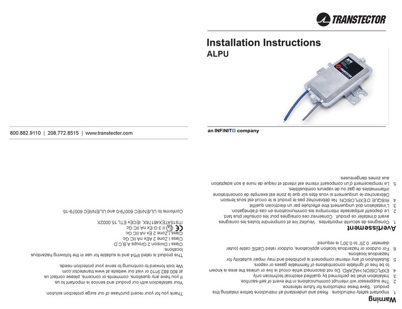
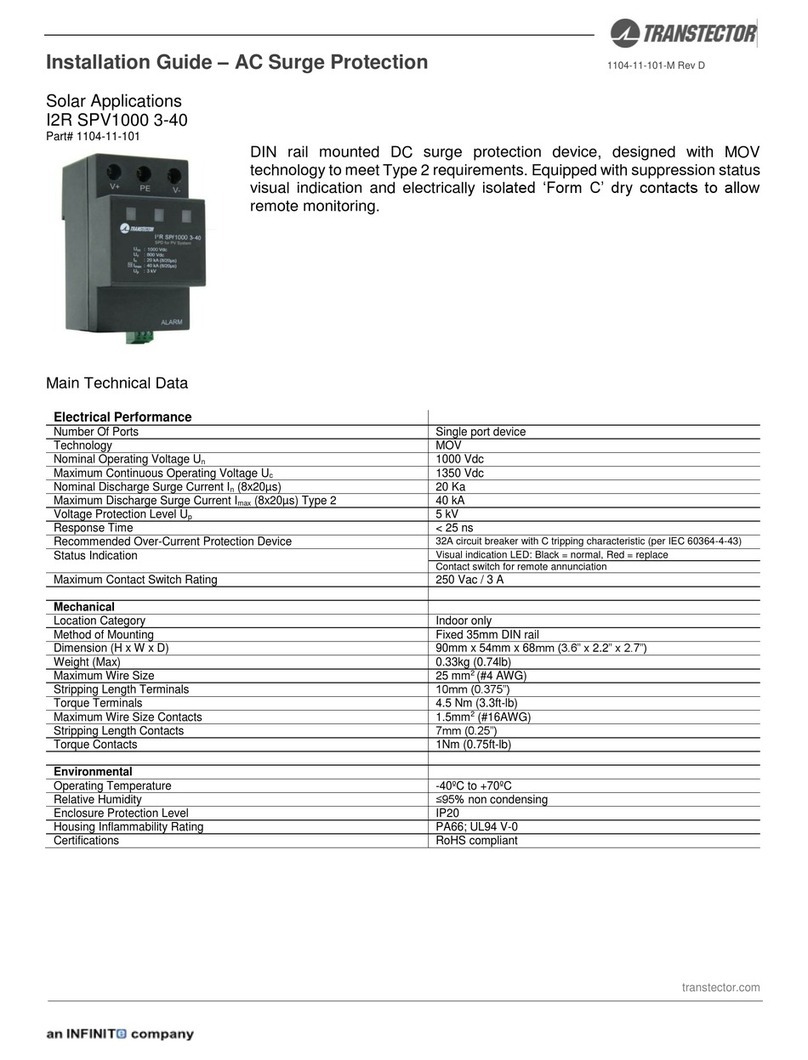
The HT-NO-ALPU-GBEP protection module is designed to provide EMP protection for equipment and
facilities per Department of Homeland Security (DHS) and the Alliance for Telecommunications Industry
Solutions (ATIS) guidelines, and have been tested for survivability to the peak threat levels of the
harsh Early Time (E1) and Intermediate Time (E2) High-Altitude (HEMP) environments as dened in
MIL-STD-188-125.
The HT-NO-ALPU-GBEP utilizes high-power, solid-state Silicon Avalanche Suppression Diodes (SASD)
to provide robust, non-degrading protection against nominal transients. These modules are intended
for use in high speed 10/1000BT Power Over Ethernet communications networks both indoors and
outdoors, including wall or pole mount applications.
MOUNTING
Mount the device as close to the equipment to be protected as possible using the provided hardware.
Mount the unit in the orientation shown, with the strain reliefs facing the ground. Mount the unit to an
outside surface using the two 4” center-to-center mounting holes using #10 hardware.
WIRING
Remove the cover by removing the two captive screws on the front of the unit.
Connect one CAT 6A shielded Ethernet cable between the unprotected unit and the suppressor using
the left internal RJ45 jack labeled “in”. Connect a second CAT 6A shielded Ethernet cable between the
unit to be protected and the suppressor using the right internal RJ45 jack labeled “out”. Secure the two
CAT 6A shielded cables using the built it cable retention. Torque strain relief to 10-15 in-lbf.
Replace cover and secure with the two captive screws. Torque to 40-45 in-lbf.
RECOMMENDED CABLE
CAT 6A shielded with shielded RJ45 connectors
GROUNDING
Proper grounding is critical for adequate HEMP protection. Keep ground wire as short as possible
between the surge protector ground and the site grounding point. Less than 3 feet, #6 AWG stranded
wire is recommended for optimum performance. Refer to local codes and equipment manufacturers
standards before installation.
The optimum ground connection on the metal enclosure unit at the mounting ange on either side is
shown in Figure 2. Attach ground wire using 1/4” hardware provided in the location shown in Figure 2.
Torque to 40-45 in-lbf.
USAGE AND MAINTENANCE
Each module should be scheduled for periodic inspection to ensure the module is operational and all
wire connections are tight. Disconnect power prior to inspection and maintenance. If the module is
damaged, contact Transtector for replacement.
AVAILABLE ACCESSORIES
A pole mount adapter kit (pn 1000-1164) is available to meet installations on a wide range of pole
diameters from 2” metal fence poles to 10” diameter utility poles.
Figure 1. Mechanical outline drawing (inches)
Figure 2. Ground Cable Installation
