TRANZSPORTER TP250 User manual
Red: 0-100-100-0 Blue: PMS 293
100-56-0-0
Color Logo use on white background only
Black Logo use on white background only
White Logo use on black background only
TP250
250 lb. Capacity
TP400
400 lb. Capacity
E1399: 022117
4 color
TIE DOWN ENGINEERING • Atlanta, GA 30336
www.tiedown.com (404) 344-0000
TIE DOWN ENGINEERING • Atlanta, GA 30336
www.tiedown.com (404) 344-0000
Instructions #08238
Updated: 2-21-17
For the Most Up to Date
Information and Instructions,
Visit the TranzSporter Web Site at
www.tranzsporter.com.
Platform Hoist
Owners Manual
Page 1 of 16

Congratulations on your Purchase of the TranzSporter Lift Hoist.
The TranzSporter Lift Hoist was designed to provide safe and continuous operation.
Features Include...
• Collapsible carriage comes with track cam followers for better tracking and handling.
• Aluminum deck and flap for lighter weight and longer life.
• Rolled goods/plywood bracket comes with unit and pins into carriage.
• Motor base is manufactured using laser cut steel tubing for extra strength and durability.
• Belt guard and foot pedal are detailed with aluminum diamond plate.
• Dual versatile brake may be operated from either side of platform hoist.
• An additional handle may be used to engage the carriage instead of using the foot pedal (#48468 handle kit sold separately).
• A 4 ft. heavy duty aluminum base track utilizes laser cut steel tube support plates for job site toughness.
• Base track features large cast aluminum feet for added stability.
• Dual band brake system for smoother stops.
• Amber colored carriage bumpers to protect against damage and wear from repeated lowering (can be rotated).
• Oversized clip pins for fast and simple removal of quick change cable drum and belt replacement.
User Responsibilities
PERFORM THE FOLLOWING AT THE START AND END OF THE WORK DAY AND AFTER
4 HOURS OF OPERATION DURING THE DAY:
• Check oil level in engine and fill according to manufacturer’s specifications.
• Check cable for smooth operation and for signs of wear.
• Check for loose bolts and tighten according to specifications.
• Check track sections and all other moving parts for excessive wear or fatigue.
• Check general condition of equipment.
• Check and confirm operator’s understanding of the proper operation for this equipment.
• When using the electric motor; check extension cords and connections for wear or damage.
• Check brake parts regularly for wear or damage.
• Check cable drum bearings, they should run smoothly when the brake is released. If there is any noise or if the cable drum does
not spin freely, replace drum bearings immediately.
• Check for minimal clearance between outer track cam followers.
WARNING:
• DO NOT OPERATE THIS EQUIPMENT IF ANY UNSAFE CONDITIONS EXIST OR OCCUR DURING OPERATION.
• KEEP TRACK SECTION CLEAR OF ALL ELECTRICAL WIRES AND EQUIPMENT. ALWAYS LOOK UP FOR ELECTRICAL WIRE PRIOR
TO MOVING TRACK SECTIONS.
• BE AWARE OF OVERHEAD OBJECTS.
• NEVER USE TRACK SECTIONS AS A LADDER.
• NEVER OPERATE HOIST WITH A HUMAN ON PLATFORM.
• NEVER STAND UNDER PLATFORM WHEN LOWERING.
• NEVER USE INDOORS OR IN AN AREA WITH POOR VENTILATION (ELECTRIC MODEL IS EXCLUDED).
• NEVER USE HOIST TO LOWER MATERIAL.
Atlanta, Georgia 30336
Page 2 of 16

(404) 344-0000 • www.tranzsporter.com
Safety Instructions
CAUTION: Please read the safety warnings and Instructions contained in this manual before operating the lift hoist. Failure
to obey the warnings contained herein could result in damage to the equipment, personal injury, or death, this information
should not be a substitute for routine accident prevention, but rather an addition to routine accident prevention.
GENERAL SAFETY INSTRUCTIONS:
1. Transport and handle your lift hoist with care.
2. Unpack the TranzSporter carefully and inspect for any damage that may occur during transportation. DO NOT USE THE HOIST IF ANY
PART IS DAMAGED.
3. Please observe all safety and warning labels attached to the hoist.
4. Use only replacement parts furnished by the manufacturer.
5. Always keep the area around the base section of the TranzSporter hoist clear to help prevent slipping, tripping or falling against the hoist.
6. DO NOT ALLOW ANYONE TO OPERATE THE TRANZSPORTER HOIST WHO HAS NOT BEEN THOROUGHLY AND PROPERLY
TRAINED IN THE CORRECT OPERATION AND USE OF THIS HOIST.
7. This hoist is manufactured to lift materials only. Do not use the lift hoist for the purpose of transporting personnel from one level to another.
8. Do not climb the TP-Series hoist or use as a personnel ladder.
9. Do not overload - maximum lifting capacity for the TP250 is 250 lbs. with a load capacity of 230 lbs. Maximum lifting capacity for the TP400
is 400 lbs. with a load capacity of 380 lbs.
10. Keep hands, feet and other body parts as well as clothing away from the track sections and moving or rotating parts of the TP-Series hoist
when starting the engine or when operating the hoist.
11. Do not allow any persons to walk or work under or near the TP-Series hoist while in operation.
12. Do not use this hoist to transport hot asphalt or any other hot molten substance from one elevation to another.
13. Store all parts of the TP-Series hoist in such a fashion as not to damage any of the components.
14. Do not operate indoors or in an area with poor ventilation. Electric motor model is excluded.
15. Never lift sheet or panel goods without the use of the plywood brackets and the tie down straps provided (See page 14).
Warning labels are attached to the TP250/400 and are weather resistant. If you notice any of these decal’s missing from your
hoist, please contact TIE DOWN ENGINEERING for a replacement label.
Remember: Safety First!!
15640-2
WARNING
DO NOT REMOVE THIS TAG!
SHOCK HAZARD
KEEP ENTIRE LIFT HOIST
CLEAR OF ALL UTILITY
AND ELECTRICAL WIRING!
15641-2
DO NOT REMOVE THIS TAG!
IMPORTANT SAFETY INFORMATION
• TOP OF HOIST MUST BE SECURED TO ROOF USING “S” HOOKS (PROVIDED)
AND TWO LENGTHS OF ROPE (NOT PROVIDED)
• BRAKE TENSION SPRINGS MUST BE CHECKED FOR CORRECT TENSIONING DAILY
(BEFORE USE) IN ORDER TO PREVENT LOAD SLIPPAGE
• KEEP BRAKE DRUMS AND BRAKE SHOES FREE OF OIL, LUBRICANTS, AND
EXCESSIVE MOISTURE, CHECK FOR DAILY WEAR AND REPLACE WHEN NECESSARY
• DO NOT OPERATE THIS UNIT IF ANY COMPONENT PARTS EXHIBIT DAMAGE
OR WEAR. THIS INCLUDES ALL TRACK SECTIONS
WARNING
SAFETY LATCH MUST BE
ENGAGED WHEN LIFT
HOIST IS NOT IN USE
DO NOT REMOVE THIS TAG!
15642-2
Instructions Inside Tube
(Remove Red End Cap to Read)
WARNING WARNING WARNING
FAILURE TO READ AND UNDERSTAND THE OPERATING
INSTRUCTIONS CAN RESULT IN PROPERTY DAMAGE,
PERSONAL INJURY OR EVEN DEATH TO USER OR OTHERS
#15726
15640-2
WARNING
DO NOT REMOVE THIS TAG!
SHOCK HAZARD
KEEP ENTIRE LIFT HOIST
CLEAR OF ALL UTILITY
AND ELECTRICAL WIRING!
15641-2
DO NOT REMOVE THIS TAG!
IMPORTANT SAFETY INFORMATION
• TOP OF HOIST MUST BE SECURED TO ROOF USING “S” HOOKS (PROVIDED)
AND TWO LENGTHS OF ROPE (NOT PROVIDED)
• BRAKE TENSION SPRINGS MUST BE CHECKED FOR CORRECT TENSIONING DAILY
(BEFORE USE) IN ORDER TO PREVENT LOAD SLIPPAGE
• KEEP BRAKE DRUMS AND BRAKE SHOES FREE OF OIL, LUBRICANTS, AND
EXCESSIVE MOISTURE, CHECK FOR DAILY WEAR AND REPLACE WHEN NECESSARY
• DO NOT OPERATE THIS UNIT IF ANY COMPONENT PARTS EXHIBIT DAMAGE
OR WEAR. THIS INCLUDES ALL TRACK SECTIONS
WARNING
SAFETY LATCH MUST BE
ENGAGED WHEN LIFT
HOIST IS NOT IN USE
DO NOT REMOVE THIS TAG!
15642-2
Page 3 of 16
Congratulations on purchasing the TranzSporter TP250 Hoist. Please read the following instructions completely before
starting assembly.
The TP250 Hoist ships in 4 units:
1) Box - Base Section, Top Cap & Brake Handle 2) Box - Collapsible Carriage & Plywood Attachments
3) Box - Motor Weldment & Manuals 4) Bundle of Tracks (3 -8 ft. Sections)
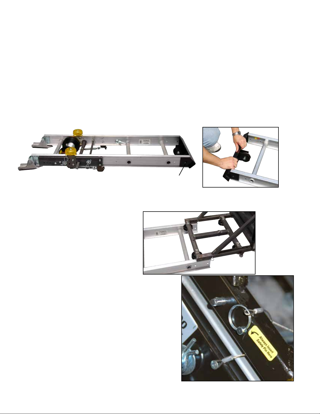
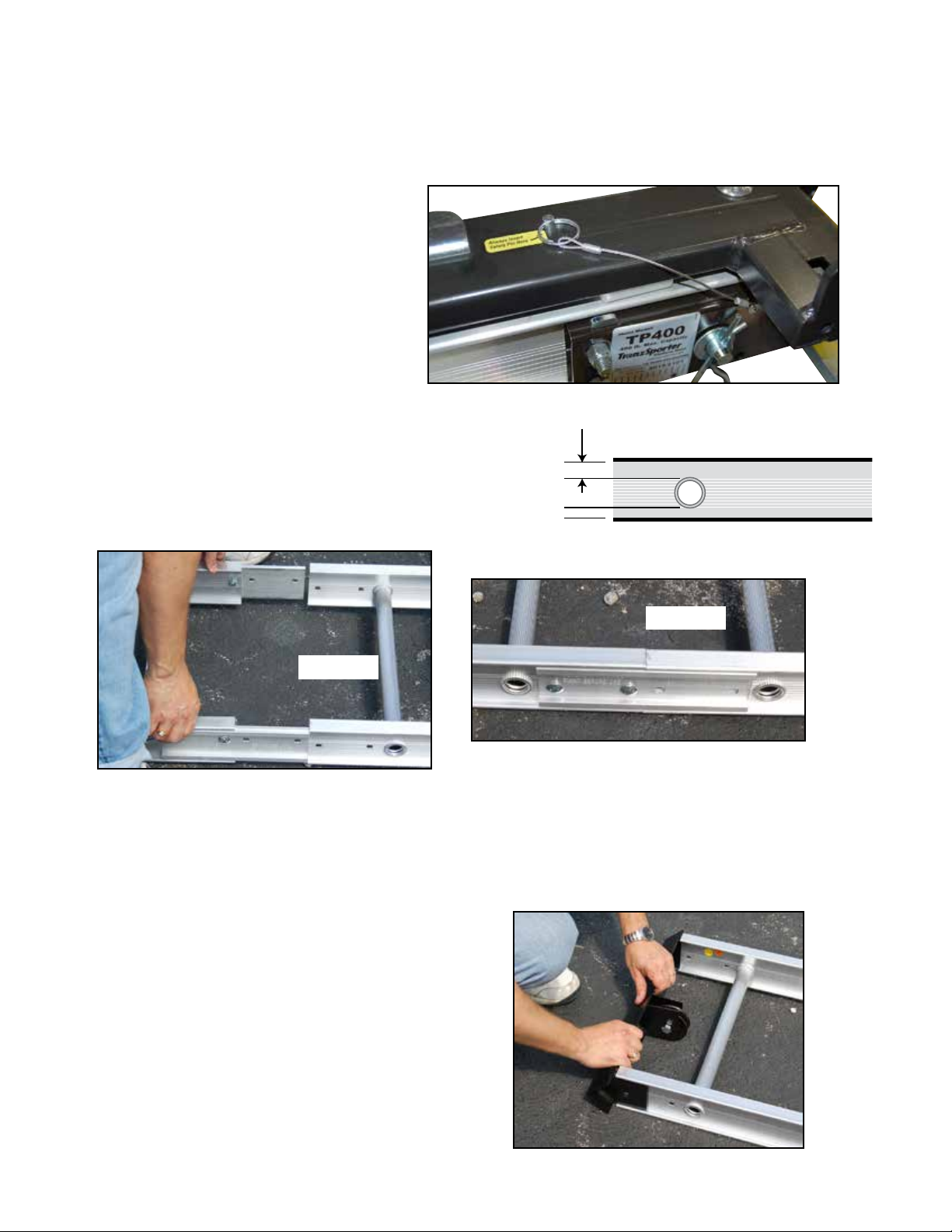
Step 4
“Roll”carriage assembly onto the base. At this time lock the base in
place using the Safety Pin as shown. Be sure to loop the lanyard over the
carriage base as shown.
Important: Always check for wear or damage to
the safety pin cable/pull ring assembly. Failure
to replace damaged safety pin cable assembly
may cause damage or personal injury.
Step 2
Remove base section from its box and place on a clean floor or assembly area. Remove the top cap with a 7/16” wrench
(one bolt/nut on each side).
Step 3
Starting at the top of the track section slide carriage
assembly onto track section so that the four rollers
connect to the top rail of the track section.
Step 1
If you have not already assembled the carriage assembly: Stop Now.
You must first assemble the carriage, follow the assembly instructions included in the #2 Box - “Collapsible Carriage & Plywood Attachments”.
Top Cap
Assembly Instructions for the TP250 Hoist
Instructions for the TP400 Hoist skip to page 7
Atlanta, Georgia 30336
Page 4 of 16
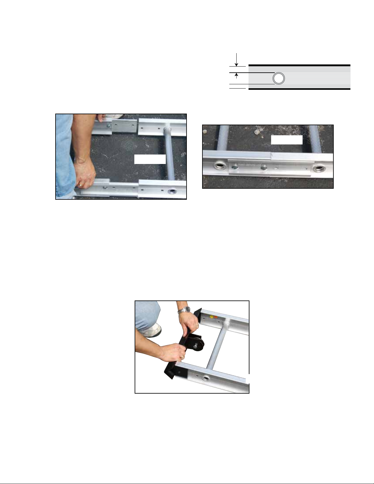
Step 5
Lay one track section on a flat floor with the “front” side up. This is
determined by the space between the track cross bar and the track
section edge as shown above.
Step 6
Attach splice plates to the bottom section of the track. Splice plates are mounted on the outside track section. Slide the top section track
into the groves on the inside track section, attach with 2 nuts and bolts per side (Pictures 4 & 5).
NOTE: DO NOT SUBSTITUTE NUTS AND BOLTS
Use 3/8”x 3/4” bolts and 3/8” nut keeps (lockwasher and nut combined).
Front
Back
Picture 5
Picture 4
Step 7
Reattach the top cap to the end of the last section of track section you intend to use. Assemble with two 3/8”x 3/4” hex head bolts with lock nuts
provided. Make sure that the top cap end slides into the outside of the track section (picture 6).
Picture 6
Assembly Instructions for the TP250 Hoist
Instructions for the TP400 Hoist skip to page 7
(404) 344-0000 • www.tranzsporter.com Page 5 of 16

Feed end cable
through pully
Unwind cable
from the back
Attach cable to
the back of the
carriage (cross bar
)
Step 10
Attach cable to the carriage assembly, pass bolt through
lock washer, washer and cable end/eye. Tighten bolt as
shown right. Bolt
Cable Eye/End
Lock Washer Washer
Carriage Cross Bar
Assembly Instructions for the TP250 Hoist
Instructions for the TP400 Hoist skip to page 7
You have completed the assembly of the TP250 Hoist
Skip to page 10 for Operation and Placement Instructions.
Step 8
From the back side of the hoist, remove the end of the cable from
the drum (shown right). It helps to attach the brake handle, use
the brake handle back releases the brake drum. The cable will
then easily un-spool. Staying on the outside (back) of the base
section and track section, take the cable to the top of the last track
section where the top cap pulley is attached.
Step 9
Feed the cable end through the pulley as shown above , and
down the front side of the track section to the back of
the carriage assembly.
Atlanta, Georgia 30336
Page 6 of 16
Assembly Instructions for the TP400 Hoist
Congratulations on purchasing the TranzSporter TP400 Hoist. Please read the following instructions completely before
starting assembly.
The TP400 Hoist ships in 4 units:
1) Box - Base Section, Top Cap & Brake Handle 2) Box - Collapsible Carriage & Plywood Attachments
3) Box - Motor Weldment & Manuals 4) Bundle of Tracks (3 -8 ft. Sections)
Step 2
Remove base section from its box and place on a clean floor or assembly area. Remove the top cap with a 7/16” wrench
(one bolt/nut on each side).
Step 3a
Starting at the top of the track section slide carriage assembly onto
track section so that the four rollers connect to the top rail of the
track section.
Step 3b
Adjust Tension Bracket - Make sure the TP400 carriage rollers are
on track, and the carriage rolls easily. There are two adjustable
track roller guides on the inside carriage assembly (see right).
Turn the nut clockwise/counter clockwise the adjust the tension (free
play) between the carriage and the tracks. If the carriage moves too
much in and out, tighten the adjustable tension bracket nut.
Correct adjustment should alow for minimal contact between the
carriage and the tracks
Step 1
If you have not already assembled the carriage assembly: Stop Now.
You must first assemble the carriage, follow the assembly instructions included in the #2 Box - “Collapsible Carriage & Plywood Attachments”.
Top Cap
Adjustable Inside Track Roller Guide
Tension Bracket
(404) 344-0000 • www.tranzsporter.com Page 7 of 16
Step 5
Lay one track section on a flat floor with the “front” side up. This is
determined by the space between the track cross bar and the track
section edge as shown above.
Step 6
Attach splice plates to the bottom section of the track. Splice plates are mounted on the outside track section. Slide the top
section track into the groves on the inside track section, attach with 2 nuts and bolts per side (Pictures 4 & 5).
NOTE: DO NOT SUBSTITUTE NUTS AND BOLTS
Use 3/8”x 3/4” bolts and 3/8” nut keeps (lockwasher and nut combined).
Front
Back
Picture 5
Picture 4
Step 7
Reattach the top cap to the end of the last section of track
section you intend to use. Assemble with two 3/8”x 3/4” hex
head bolts with lock nuts provided. Make sure that the top cap
end slides into the outside of the track section (shown right).
Assembly Instructions for the TP400 Hoist
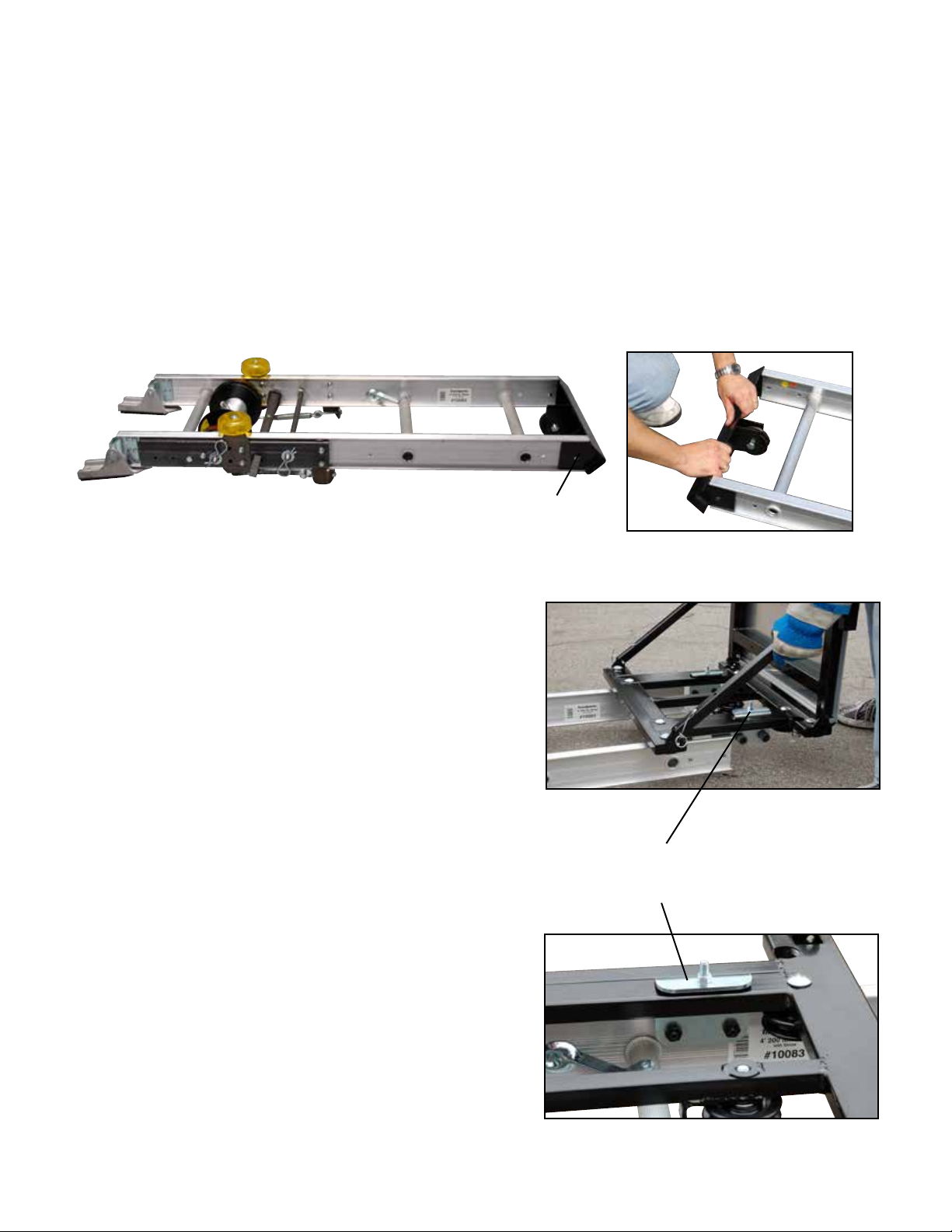
Step 4
“Roll”carriage assembly onto the base. At this time lock
the base in place using the Safety Pin as shown.
Important: Always check for wear
or damage to the safety pin cable/
pull ring assembly. Failure to replace
damaged safety pin cable assembly
may cause damage or personal injury.
Atlanta, Georgia 30336
Page 8 of 16

Assembly Instructions for the TP400 Hoist
Double back/feed end
cable through pully on
the back of carriage
(cross bar)
Feed end cable
t
hrough pully
Unwind cable
from the back
Attach cable to
the back side of the
pully bracket
Step 8
From the back side of the hoist, remove the end of the cable from
the drum (shown right). It helps to attach the brake handle, use the
brake handle back releases the brake drum. The cable will then
easily un-spool. Staying on the outside (back) of the base section
and track section, take the cable to the top of the last track section
where the top cap pulley is attached.
Step 10
Remove the nyloc nut/washer/lock washer, from the
top cap assembly, place the eye end over the bolt,
replace the washer/lock washer and tighten the nyloc
nut as shown right.
Bolt
Cable Eye/End
Nyloc Nut
Cable is
looped around
carriage pully
Lock Washer
Washer
Top Cap
Step 9
Feed the cable end through the pulley as shown above,
and down the front side of the track section to the
back of the carriage assembly.
Feed the cable end through the pully on back of
TP400 carraiage. Return the cable end to the top cap.
(404) 344-0000 • www.tranzsporter.com Page 9 of 16

Engine Base
Assembly Arm
Engine Base
Assembly Arm Retaining
Rings
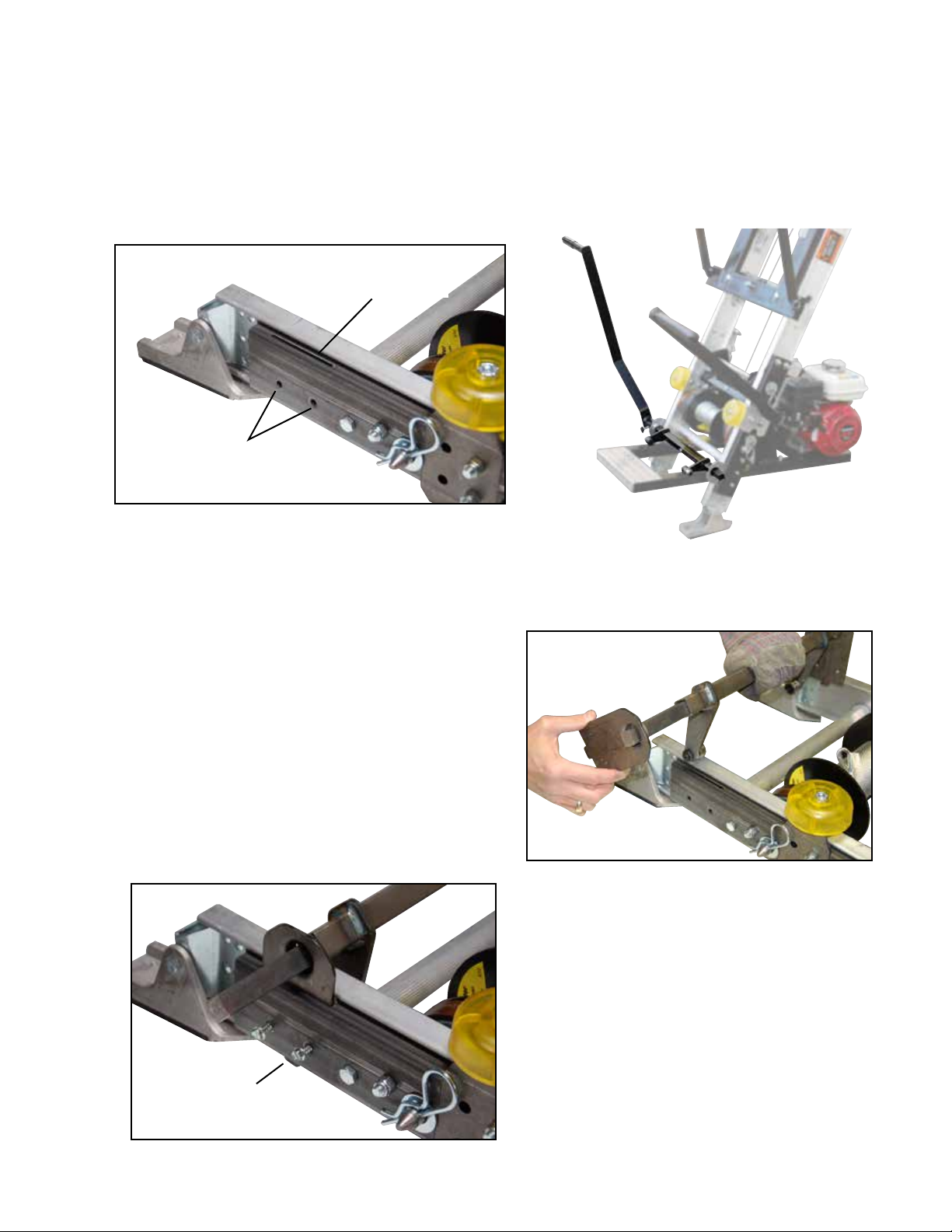
Step 12
Mount the motor assembly to the base unit; from behind the hoist; the foot pad of the motor base slides under the track base section,
while “hanging” the motor base. The motor assembly arms must fit outside the two retainer rings shown above.
Step 11
See “Raising Hoist” instructions (page 12 ) for proper positioning/placement of base at the set at job site.
Step 13
Before starting the engine...
Attach the “V” belt to the large pulley (next to cable drum assembly on
track base), then to the small pulley on the motor base (shown right).
Step 14
Slide the brake handle over the brake arm and tighten thumb screw provided.
Step 15
If needed, remove plywood brackets and rotate 90 degrees. Secure the
two plywood/rolled goods brackets with push pins provided (shown right).
IMPORTANT:
When lifting panel goods, panels must be secured with tie down straps.
Atlanta, Georgia 30336
Page 10 of 16
Assembly Instructions TP250/400 Secondary Handle Kit #48468 (Purchased Separately)
Allows use of a left side handle to engage the motor and carriage. It is highly recommended when using with the Solar/Plywood Saddle
Carriage. Can be used for both TP250 & TP400 models.
Parts included with the Secondary Handle Kit:
1) Handle. 2) Pivot/Brake Weldmont
3) 2 Mounting Plates 4) 4 Screws
Step 1
Lay the base section flat on a hard surface. Locate the mounting slot
and holes on the bottom portion of the base section.
Step 2
With one hand, hold the pivot/brake weldment just
above the lower base section. Slide the mounting
plates over the pivot/brake rod. Make sure the raised
hole side of the mounting plates goes on the inside.
Step 3
Holding the pivot/brake weldment/mounting plates with one
hand; slide the mounting plates into the slots on both sides
of the base section. The plates should slide into place with the
notch fitting thru the base section.
Using the two holes provided; insert two screws per side.
Tighten screws using a screw driver or wrench.
Attach secondary handle on either side of the hoist.
Mounting Holes
Mounting Plate
“Notch”
Mounting Slot
(404) 344-0000 • www.tranzsporter.com Page 11 of 16

Raising the Track Section Assembly
WARNING: KEEP TRACK SECTIONS CLEAR OF ALL ELECTRICAL WIRES
AND EQUIPMENT. BE AWARE OF OVERHEAD WIRES BEFORE RAISING
TRACK SECTIONS. ELECTRICITY KILLS!
The hoist assembly is extremely top heavy and must be kept under control at all times. Two alternate
methods are suggested for raising the platform hoist to the operating position. See Track Section
Support Chart (page 13) for approximate distances of the base from the bottom track.
Procedure “A”
This procedure requires two or preferably three men.
1. Lay the assembled track sections with the platform attached parallel to the building wall that is to support the hoist.
2. Tie a rope to the head bracket and have the man on roof pull up the hoist while the other man on the ground braces the shoes on
the bottom base section to prevent slippage of the hoist shoes. The third man on the ground may aid in erecting by “walking”
the hoist up hand over hand by the rungs.
3. When the hoist reaches a vertical position, carefully turn the hoist 90 degrees with the platform pointing away from the building.
Move the bottom of the hoist away from the building 1/4 of the height of the building where the top of the hoist is to be supported.
Make allowances for overhang.
Procedure “B”
1. Place track section assembly perpendicular to the building with the bottom shoes of the steel bottom section resting against the
building to prevent slipping.
2. Tie a rope to the top bracket and have the man on the roof pull up the hoist while the other man on the ground braces the shoes
on the steel bottom base section to prevent slippage of the hoist shoes. The third man on the ground may aid in erecting by
“walking” the hoist up hand over hand by the rungs.
3. When the hoist reaches a vertical position, move the bottom of the hoist away from the building 1/4 of the height of the building
where the top of the hoist is to be supported. Angle of track sections from building should be between 18 and 20 degrees.
Make allowances for an overhang. See track section chart for approximate distances of the base from the building.
4. Tie the track section to the roof with a rope fastened to a cross tie on the top bracket to prevent slippage of the track section.
DO NOT TIE ROPE TO THE RAILS - THIS WILL PREVENT THE PLATFORM FROM OPERATING PROPERLY.
5. Mount the power unit to the top rung of the bottom base section. Attach the V-belt to the pulley on the power unit. Slide the
brake handle over the brake arm and install the locking pin provided.
6. Remove any ropes used to secure the platform during transportation.
7. Make certain the shoes on the steel bottom section are firmly resting on level ground. This will help to prevent track section
slippage or uneven loading of the track section which could cause damage or injury to personnel and/or to equipment.
Atlanta, Georgia 30336
Page 12 of 16
Gasoline Engine
1. Handle fuel with care. It is EXTREMELY flammable and explosive under certain conditions.
2. Do not smoke, allow open flames or sparks to be present during the refueling operation.
3. Use only an approved fuel container to transport fuel.
4. Do not fuel while engine is hot - allow to cool before attempting the refueling operation.
5. Replace all fuel tank caps securely and wipe the spilled fuel before restarting engine.
6. Do not operate the TP-Series gasoline engine in an enclosed area. The exhaust can be especially hazardous and cause death
in an enclosed area.
7. Stop the engine and lower the platform when leaving the vicinity of the hoist.
8. Always stop the engine, lower the platform, wait for all moving parts to stop, and allow the engine to cool before disassembling
or moving the hoist.
9. Disconnect the spark plug wire from the plug before disassembling or moving the hoist.
10. DO NOT store the engine in an enclosed area.
11. Allow engine to cool before storing.
12. DO NOT store engine where it might be subjected to flames, sparks, extreme heat or any other source of combustion.
15640-2
WARNING
DO NOT REMOVE THIS TAG!
SHOCK HAZARD
KEEP ENTIRE LIFT HOIST
CLEAR OF ALL UTILITY
AND ELECTRICAL WIRING!
15641-2
DO NOT REMOVE THIS TAG!
IMPORTANT SAFETY INFORMATION
• TOP OF HOIST MUST BE SECURED TO ROOF USING “S” HOOKS (PROVIDED)
AND TWO LENGTHS OF ROPE (NOT PROVIDED)
• BRAKE TENSION SPRINGS MUST BE CHECKED FOR CORRECT TENSIONING DAILY
(BEFORE USE) IN ORDER TO PREVENT LOAD SLIPPAGE
• KEEP BRAKE DRUMS AND BRAKE SHOES FREE OF OIL, LUBRICANTS, AND
EXCESSIVE MOISTURE, CHECK FOR DAILY WEAR AND REPLACE WHEN NECESSARY
• DO NOT OPERATE THIS UNIT IF ANY COMPONENT PARTS EXHIBIT DAMAGE
OR WEAR. THIS INCLUDES ALL TRACK SECTIONS
WARNING
SAFETY LATCH MUST BE
ENGAGED WHEN LIFT
HOIST IS NOT IN USE
DO NOT REMOVE THIS TAG!
15642-2

(404) 344-0000 • www.tranzsporter.com
WARNING: BEFORE LOWERING THE TRACK SECTIONS, CAREFULLY CHECK FOR OVERHEAD OBJECTS
AND POWER LINES. ELECTRICITY KILLS
Raising the platform with or without load
WARNING: THE OPERATOR OF THIS HOIST UNIT SHOULD WEAR APPROPRIATE SAFETY EQUIPMENT WHICH SHOULD
INCLUDE APPROVED HAND PROTECTION, HEAD PROTECTION AND EYE PROTECTION.
To raise the platform on the TP250, face the platform and stand as far as possible from the hoist to operate. Place your foot on the
foot control pad to engage the motor to the cable drums V belt, permitting the platform to roll up the track section. When the platform
reaches the top, release foot IMMEDIATELY. This will apply the self energizing brakes. Move away from the hoist while the load is
being removed from the platform.
Lowering the platform
To lower the carriage, stand to the right or left side of the hoist and grasp the brake handle. Lightly feather the platform down by
engaging and disengaging the brake to slow the carriage. Lower the carriage to the ground at a slow speed (not to exceed 50/feet per
minute). Continue to decelerate the platform as it nears the ground to prevent damage to the platform or bottom bumper stops.
DO NOT USE THE HOIST TO LOWER MATERIALS.
CAUTION: NEVER APPLY THE BRAKE ABRUPTLY - BROKEN HOIST CABLES AND/OR SEVERE INJURY TO PERSONNEL OR
EQUIPMENT MAY OCCUR. MAKE CERTAIN PLATFORM DOES NOT EXCESSIVELY STRIKE THE BOTTOM BRACE STOPS UPON
REACHING THE BOTTOM OF THE TRACK SECTION.
Lower and dismantle the platform hoist assembly in the reverse of the erection procedure, observing all safety procedures.
Track Section Chart - Brace Support and Proper Set Up Distance at Job Site
Track lengths in excess of 28 feet require the use of the telescoping brace (#60005). The table below provides the suggested
information for the distance of the bottom track from the building and the location of the track support for various conditions.
Building Length of Base To Track Brace Location
Height Track Building Cross Tie from Bottom
12’ 16’ 4’-6” Not Required
16’ 20’ 5’-0” Not Required
20’ 24’ 6’-6” Not Required
24’ 28’ 6’-6” Not Required
28’ 32’ 7’-6” 11th and 13th
32’ 36’ 8’-0” 14th and 16th
36’ 40’ 9’-0” 19th and 21st
40’ 44’ 10’-0” 26th and 25th
42’ 44’(max) 10’-6” 25th and 27th
REPAIR INFORMATION
Your lift hoist is designed to provide years of service, however, when your hoist requires parts, service or repairs, please contact
your nearest authorized dealer, or call 1-800-241-1806, Ext. 1525 for information on where to take your platform hoist.
Page 13 of 16
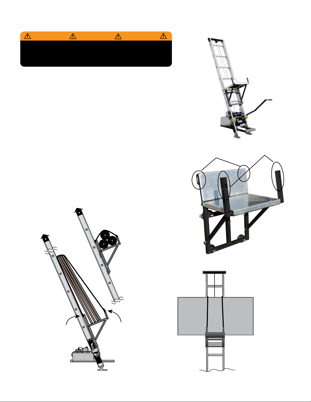
Plywood/Flat Panel Tie Down and Lifting Instructions
Plywood Bracket
Tie Downs -
Secure straps through
slotted holes provided.
Tie down strap
must loop over
all materials and
must attach at
tie down locations.
NOTE:
ALWAYS CENTER FLAT
PANEL LOADS
Platform Back
Flap Tie Down -
Secure straps through
flap slots provided
on back.
WARNING WARNING WARNING
FAILURE TO READ AND UNDERSTAND THE OPERATING
INSTRUCTIONS CAN RESULT IN PROPERTY DAMAGE,
PERSONAL INJURY OR EVEN DEATH TO USER OR OTHERS
• Use the proper tie down equipment - If you are not securing your cargo with the
proper safety straps, it could come loose during lifting, resulting in injury or death.
• Never hoist anything wider than the 8” - larger plywood sheets can make
controlling your hoist difficult and dangerous, especially when considering
windy conditions. Wide panels must be centered to prevent tipping.
• Attach your safety straps to slotted tie-down points - Do not hook your tie-down straps
to the plywood, straps must pass over the top. Secure your safety straps to the carriage
top flaps slotted holes (the metal frame) and to the plywood brackets only (Refer
to the drawings for tie down slot locations).
• Maintain a manageable speed - The wind’s effects on sheets of plywood or panel
goods, as well as the higher center of gravity, can make hoisting difficult
and dangerous.
• Check all tie-down connections. Safety straps may come loose during transport.
Always check strap for damage or wear. Replace when damaged or worn.
Tie Down Strap Slots Tie Down Strap Slots
Plywood Bracket
Tie Downs -
Secure straps through
slotted holes provided.
Tie down strap
must loop over
all materials and
must attach at
tie down locations.
NOTE:
ALWAYS CENTER FLAT
PANEL LOADS
Platform Back
Flap Tie Down -
Secure straps through
flap slots provided
on back.
WARNING WARNING WARNING
FAILURE TO READ AND UNDERSTAND THE OPERATING
INSTRUCTIONS CAN RESULT IN PROPERTY DAMAGE,
PERSONAL INJURY OR EVEN DEATH TO USER OR OTHERS
Atlanta, Georgia 30336
Page 14 of 16

TIE DOWN ENGINEERING • Atlanta, GA 30336
www.tiedown.com (404) 344-0000
TRANZSPORTER PRODUCT LINE LIMITED WARRANTY
Tie Down Engineering will repair or replace, free of charge, any part, or parts of the TranzSporter lift hoist that are defective
in material or workmanship or both. The limited warranty is in effect for 90 days from date of purchase. Return the defective
unit to the dealer or contact Tie Down direct at 800-241-1806, x1525.
This warranty does not apply to damage or loss caused by any or all of the following circumstances or conditions:
• Damage caused during assembly or installation.
• Parts, accessories, materials or components used with or replacing any TIE DOWN lift hoist part not obtained from or
approved in writing by TIE DOWN.
• Misapplication, misuse and failure to follow the directions or observe cautions and warnings on installation, operation,
application, inspection or maintenance specified in any TIE DOWN quotation, acknowledgment, sales literature,
specification sheet or installation instruction and service manual ("applicable literature").
• Use of product in any other application other than those described in TIE DOWN’s product information materials.
If any TIE DOWN products are found upon TIE DOWN's examination to have been defective when supplied, TIE DOWN will
either: credit the purchaser's account for the purchase price of the TIE DOWN product; replace the TIE DOWN product; or
repair the product. TIE DOWN has sole discretion in choosing which option to provide. For this LIMITED WARRANTY to
apply, TIE DOWN must receive notice of the alleged defect within 30 days of either the discovery of the alleged defect or
the expiration of the warranty period, whichever is earlier. Any claim not made within this period shall conclusively be
deemed waived.
If requested by TIE DOWN, purchaser shall return the alleged defective product to TIE DOWN for examination at purchasers
expense. TIE DOWN will not pay for expenses incurred in returning a product to TIE DOWN without TIE DOWN's prior written
authority. TIE DOWN shall not be liable for any other expenses purchaser incurs to remedy any defect. Purchasers waive
subrogation on all claims under any insurance.
Limitation of Liability: It is expressly agreed that the liability of TIE DOWN is limited and TIE DOWN does not function as
an insurer. THE REMEDIES SET FORTH IN THIS WARRANTY SHALL CONSTITUTE THE EXCLUSIVE REMEDIES AVAILABLE TO
THE PURCHASER OR USER AND ARE IN LIEU OF ALL OTHER REMEDIES, EXPRESS OR IMPLIED. THE LIABILITY OF TIE DOWN,
WHETHER IN CONTRACT, IN TORT, UNDER ANY WARRANTY OR OTHERWISE, SHALL NOT EXCEED THE PURCHASE PRICE OF
THE PARTICULAR PRODUCT MANUFACTURED, SOLD OR SUPPLIED BY TIE DOWN.
To Obtain Technical Assistance: To enable TIE DOWN to respond to a request for assistance or evaluation of customer or
user operating difficulty, please provide at a minimum the following information by calling 404-344-0000:
• Model number, serial number and all other data on the specific component which appears to be involved in the difficulty.
• The date and from whom you purchased your TIE DOWN product.
• State your difficulty, being sure to mention at least the following: application, nature of load involved, and
weight of the load.
THIS WARRANTY DOES NOT COVER NOR EXTEND TO INCIDENTAL OR CONSEQUENTIAL DAMAGE. Some states do not
allow the exclusion or limitation of incidental or consequential damages, so the above limitation or exclusion may not apply
to you. This warranty gives you specific legal rights, and you may also have other rights which vary from state to state.
No representative has authority to make any representation, promise or agreement except as stated in this Limited
Warranty. TIE DOWN reserves the right to make design and other changes upon its products without any obligation to
install the same on any previously sold or delivered products.
THERE ARE NO WARRANTIES WHICH EXTEND BEYOND THOSE DESCRIBED ABOVE. EFFECTIVE JANUARY 2015 THIS
WARRANTY SUPERSEDES ALL PRIOR WARRANTIES, WRITTEN OR IMPLIED.
E1401/Rev. 030615
Page 15 of 16
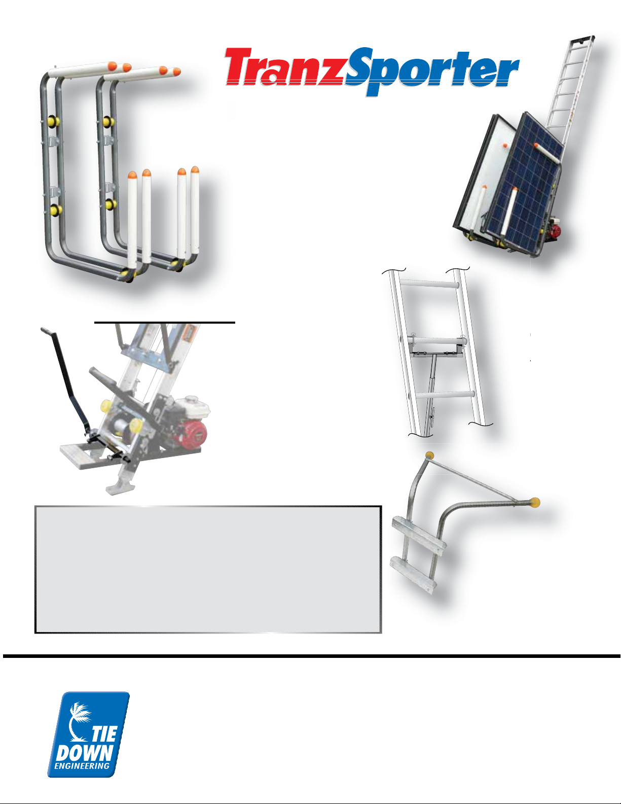
Hoist Accessories
H
Solar/Plywood Panel Saddle Carriage
Allows lifting of four solar panels or plywood
sheets. Unique design allows panels to roll
off towards the contractor, preventing leaning
while on the roof top. Requires roof top
anchoring; straps included with carrier.
Solar/Plywood Panels attach to TP400
carriage frame. Solar/Plywood Panel Kit
#48469 is a complete carriage system for use
with the TP250.
Secondary Handle Kit
Allows use of a left side handle to
engage the motor and carriage. It
is highly recommended when
using with the Solar/Plywood
Saddle Carriage. Includes all
hardware brackets and handle.
Can be used for both TP250 &
TP400 models.
Part # Hoist Accessories
48467 TranzSporter Solar/Plywood panel accessory for TP400 Platform Hoist
48469 Complete Solar Carrier for TP250
48468 Secondary Handle Kit for TP250 & TP400
10092 4 ft. TranzSporter Track Section for TP250 and TP400
10091 8 ft. TranzSporter Track Section for TP250 and TP400
60005 Telescopic Support Brace for TP250 and TP400
48599 TranzSporter Stand-Off/Stabilizer
Telescopic
Support Brace
Used with TP250 &
TP400 models over
28 ft.
Telesco
p
Su
pp
ort
Used wi
t
TP400
m
28 ft.
Solar/Plywood Saddle
Stand-Off/Stabilizer
This unique stabilizer attaches
to the platform hoist track
section allowing proper
stand-off from roof and gutter.
Helps prevent costly gutter
damage when placed directly
on roof. Assembly required.
Roofing Products Division
TIE DOWN ENGINEERING
Atlanta, Georgia 30336
800-241-1806 • 404-344-0000
ISO 9001:2008 Certification
Trade, brand, names and drawings are the intellectual property of
TIE DOWN ENGINEERING. ©2014 TIE DOWN, Inc.
Manual #08238 (Rev. 3-23-2015) Page 16 of 16
Other manuals for TP250
3
This manual suits for next models
1
Table of contents
Other TRANZSPORTER Lifting System manuals


Popular Lifting System manuals by other brands

Auton
Auton 3000-INH installation manual

Simpro
Simpro Dumpmaster Service manual

Joerns Healthcare
Joerns Healthcare Hoyer HPL402 User instruction manual & warranty

Rotary
Rotary MCH14 Series Installation-safety-operation-maintenance

AMGO
AMGO A240 Installation and service manual

Handicare
Handicare SystemRoMedic BariVest XXXL manual

The Handy
The Handy OX 1800 operating instructions

LGMG
LGMG A30JE Maintenance manual

Custom Elevator
Custom Elevator HYD-7.540 owner's manual

Liko
Liko UltraTwin FreeSpan Instruction guide

American Access
American Access Entrada Series installation manual

Strong Racks
Strong Racks PowerRax Double Bike Lift manual


