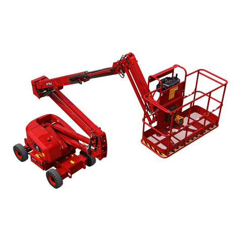
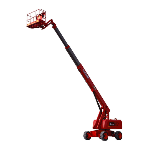
LGMG A30JE User manual

LGMG North America Inc.
Maintenance Manual
A30JE
Articulated Boom
Mobile Elevating Work Platform
ANSI
!
WARNING
Before operation and maintenance, the
drivers and service personnel shall
always read and thoroughly understand
all information in this manual. Failure to
do so may result in, fatal accidents or
personal injury.
This manual must be kept with this
machine at all times.

This page left blank intentionally

LGMG North America Inc. Maintenance Manual
I
Contents
Chapter 1 Maintenance...............................................................................1
1.1 Compliance and Obedience.............................................................. 3
1.2 Checking the Safety Manual ............................................................. 3
1.3 Check the Labels and Signs ............................................................. 3
1.4 Every Day or every 8 Hours.............................................................. 3
1.5 Every 100 Hours ............................................................................... 5
1.6 Every 250 Hours ............................................................................... 5
1.7 Every 500 Hours ............................................................................... 9
1.8 Every 1000 Hours ............................................................................. 9
1.9 Every 2000 Hours ........................................................................... 10
1.10 Regular maintenance.....................................................................11
1.11 Routine Inspection and Maintenance Intervals.............................. 12
Chapter 2 Schematic Diagram ..................................................................15

LGMG North America Inc. Maintenance Manual
II
Foreword
Thank you for choosing to use this Mobile Elevating Work Platform from LGMG North America. This
machine is designed according to ANSI A92.20-21 and CSA B354.6-17. The information specified in this
manual is intended for the safe and proper operation of this machine for its’ intended purpose.
For maximum performance and utilization of this machine, thoroughly read and understand all the
information in this manual before starting, operating, or performing maintenance on this machine.
Ensure all preventive maintenance to the machine is performed according to the interval specified in the
maintenance schedule.
Keep this manual with this machine for reference at all times. When the ownership of this machine is
transferred, this manual shall be transferred with this machine. This manual must be replaced
immediately if it is lost, damaged, or becomes illegible.
This manual is copyrighted material. The reproduction or copy of this manual is not allowed without the
written approval of LGMG North America.
The information, technical specifications and drawings in this manual are the latest available when this
manual is issued. Due to continuous improvement, LGMG North America reserves the right to change
the technical specifications and machine design without notice. If any specifications and information in
the manual are not consistent with your machine, please contact the service department of LGMG North
America.
△
!WARNING
Only personnel who have been properly trained and qualified to operate or maintain
this machine can operate, repair and maintain this machine.
Improper operation, maintenance, and repair are dangerous and can cause personal
injury and death.
Before any operation or maintenance, the operator shall thoroughly read this
manual. Do not operate, perform any maintenance or make any repairs on this
machine before reading and understanding this manual.
The user shall load the platform strictly according to the load rating of the platform.
Do not overload the platform or make any modifications to the platform without
permission from LGMG.
The operation regulations and preventions in this manual are only applicable for the
specified use of this machine.
All dealers, owners, users, operators, lessors, lessees, and brokers must comply
with appropriate section(s) of applicable A92 standards.

LGMG North America Inc. Maintenance Manual
III
Safety Precautions
The operator of this machine shall understand and follow the existing safety regulations of state and
local governments. If these are unavailable, the safety instructions in this manual shall be followed.
To help prevent accidents, read and understand all warnings and precautions in this manual before
operation or performing maintenance.
It is impossible to foresee every possible hazard and the safety instructions in this manual may not cover
all safety prevention measures. Always ensure the safety of all personnel and protect the machine
against any damage. If unable to confirm the safety of some operations, contact LGMG North America.
The operation & maintenance prevention measures listed in this manual are only applicable to the
specified uses of this machine. LGMG North America assumes no responsibility if this machine is used
beyond the range of this manual. The user and the operator shall be responsible for the safety of such
operations.
Do not perform any operation forbidden in this manual in any situation.
The following signal words are applicable for identifying the level of safety information in this manual.
△
! DANGER:
An imminent situation, that if not avoided, will result in severe injuries or death. This
is also applicable to situations that will cause serious machine damage, if not
avoided.
△
! WARNING:
A potentially dangerous situation, that if not avoided, may result in severe injuries or
death. This is also applicable to situations that may cause serious machine damage,
if not avoided.
△
! NOTICE:
A situation, that if not avoided, may result in minor or intermediate injury. This is also
applicable to situations that may cause machine damage or shorten machine service
life.

LGMG North America Inc. Maintenance Manual
IV

LGMG North America Inc. Maintenance Manual
1
Chapter 1 Maintenance

LGMG North America Inc. Maintenance Manual
2

LGMG North America Inc. Maintenance Manual
3
1.1 Compliance and
Obedience
1) You are properly trained and qualified to
operate and maintain the machine safely.
2) All safety regulations in this manual,
workplace safety regulations and
applicable government laws and
regulations must be read, understood and
complied.
3) Equipped with PPE, such as helmet, seat
belt, safety shoes, goggles, protective
clothing, insulating gloves, insulating shoes,
etc., and in good physical condition.
4) When maintenance and repair procedures
are being performed, many dangers
indicated in the Operation Manual will also
become potential safety hazards.
5) Scheduled maintenance and repair can
only be completed by trained and qualified
maintenance technician.
6) Dispose of waste materials in accordance
with government regulations and workplace
regulations.
7) Only parts and consumables approved by
the LGMG can be used.
8) Always perform functional tests after
maintenance.
1.2 Checking the Safety
Manual
It is necessary for safe equipment operation to
keep the Operator and Safety Manual in good
condition. The manual shall be stored in a
container in the working platform provided by
each machine. An illegible or missing manual
will not provide the necessary safety and
operation information for safe operation.
1) Check that the storage container is on site
and in good condition.
2) Check that the Operator, Responsibility,
and Safety Manual is complete in the
storage container on the work platform.
3) Check that each page of the manual is
identifiable and in good condition.
4) Put the manual in the storage file box after
use.
△
! If you need to replace the manual,
please contact the company’s service
personnel.
1.3 Check the Labels and
Signs
It is necessary for safe operating equipment to
keep all safety and instructions labels and signs
in good conditions. Labels are used to remind
operators and staff of the possible hazards
when operating this equipment. User operation
and maintenance information is also provided.
An illegible label does not remind the staff of
steps or hazards, and may also result in unsafe
operating conditions.
Refer to the label section in this manual and use
the label menu and instructions to check
whether all labels are in place.
Check all the labels for clarity and damage and
immediately replace any damaged or illegible
ones.
△
! If you want to replace the label,
please contact the company’s service
personnel.
1.4 Every Day or every 8
Hours
1.4.1 Check for Damaged, Loose
or Missing Parts
This step is performed every 8 hours or every
day, whichever comes first.
Carrying out daily equipment status check is
necessary for ensuring safe equipment
operation and maintaining good equipment
performance. Incorrect positioning, repairing
damaged equipment, and loose or missing parts
may result in unsafe operating conditions.

LGMG North America Inc. Maintenance Manual
4
1) Check for damaged parts for the whole
platform, and check for incorrect installation
or missing parts and components,
including:
Electrical components, wirings and cables
Hydraulic hoses, connectors, valve blocks
and hydraulic cylinders
Hydraulic tanks
Wear-resistant pads
Tires and wheels
Limit switch and horn
Nuts, bolts and other fasteners
Platform entrance door
Indicators and alarms
Platform controller
2) Check the entire machine for:
Cracks in welds or structural components
Whether the platform, boom and chassis
are deformed or have cracked weld joints.
Indentation or damage to the machine
Ensure that all structural components and other
key components are complete and all relevant
fasteners and pins are in the correct position
and tightened.
1.4.2 Check the Hydraulic Oil
Level and Leakage
Inspect hydraulic oil level every 8 h or every
day.
Maintaining the hydraulic fluid at the proper oil
level is essential for machine operation. If the
hydraulic oil is at an unsuitable oil level, the
hydraulic components may be damaged.
Through daily inspections, the inspector can
determine changes in the hydraulic oil level
which can indicate problems with the hydraulic
system.
△
! CAUTION: This step should be
performed when the platform is in the
retracted state.
Park the vehicle on the flat site.
Fully retract the boom.
Figure 1-1 Oil Level Sight Gauge
Examine the oil level on the hydraulic oil
tank, i.e., level shall fall within the “M” range
shown as Figure 1-1, and in the case of
level lower than “M”, it is necessary to add
hydraulic oil.
Inspect hydraulic oil leakage every 8 h or
daily.
Grade
Brand
Rando MV32
Chevron
△
!CAUTION: Do not top off with
incompatible hydraulic fluids.
Hydraulic fluids may be incompatible
due to the differences in base additive
chemistry. When incompatible fluids
are mixed, insoluble materials may
form and deposit in the hydraulic
system, plugging hydraulic lines,
filters, control valves and may result in
component damage.
△
! CAUTION: Personal injury danger,
leaking hydraulic oil can penetrate or
burn skin. Wear goggles and protective
gloves.
Leakage of high-pressure oil may be
invisible to eyes, use cardboard or wooden
boards as a search tool for hydraulic oil
leakage. Hands shall be prohibited from
being used for leakage confirmation.
Inspect oil drops or residual oil on the
following components:
Hydraulic oil tank, filter, pump, hydraulic oil

LGMG North America Inc. Maintenance Manual
5
cylinder, motor, valve block and hydraulic
tubing.
Inspect oil drops or residual oil at the
following areas:
Rear of boom, fly jib, upper side of turntable,
upper and lower sides of chassis, and
ground underneath equipment.
1.5 Every 100 Hours
1.5.1 Maintenance of worm-Type
Slewing Drive
Check lubrication in the turntable bearing and
the swing gearbox at intervals of 100 hours. It is
necessary for maintaining performance and
maintenance life to lubricate the turntable
bearing frequently. Incorrect lubrication will
cause damage to components.
There are three positions to be lubricated on the
worm-type slewing drive assembly, i.e.,
lubrication of the roller path (Position I),
lubrication of the engaging position (Position II)
between the worm and the slewing bearing, and
lubrication of the tapered roller bearing (Position
III). The specific lubrication positions are shown
as below:
Figure1-2 worm-Type Slewing Drive
Position I: Lubrication of the roller path:
Lubrication method: Continuously inject
lubricating grease into the injection port of
lubricating grease while rotating the slewing
reducer
Model of the lubricating grease: 3#
lubricating grease
Position II: Lubrication of the engaging position
between the worm and the slewing bearing
Lubricating method: Continuously inject
lubricating grease into the injection port of
lubricating grease while rotating the slewing
reducer
Model of the lubricating grease: 3#
lubricating grease
Position III: Lubrication of the tapered roller
bearing:
Lubricating method: Direct lubrication
Model of the lubricating grease: 3#
lubricating grease
△
! CAUTION: In the case of an
extremely dirty working environment,
increase the oil filling frequency.
1.5.2 Grease the Exposed Piston
Rod
If storing the machine for a long time with the
piston rod exposed, carry out the maintenance
monthly; if not, carry it out quarterly.
Component requiring maintenance:
Base boom lift cylinder.
Tower boom lift cylinder.
Grease specification:
Lithium-based grease and hydraulic oil mix, with
the ratio of lithium-based grease to hydraulic oil
as 3:1.
Maintenance procedure:
1) Apply the mix evenly onto lint-free wipers.
2) Fully raise the tower boom and apply the
mix evenly to the surface of the exposed
piston rod using lint-free wipers.
3) Fully lower the tower boom and fully raise it.
Then wipe the residual mix off the piston
rod using lint-free wipers.

LGMG North America Inc. Maintenance Manual
6
1.6 Every 250 Hours
1.6.1 Check the Batteries
This check should be performed every 250h or
three months, whichever comes first.
Good battery condition is critical to normal
vehicle performance and safe operation.
Improper electrolyte levels or damaged cables
and wires may result in component damage and
dangerous situations.
△
! Risk of electric shock
Any live operation can cause serious
personal injury or death. Remove all
rings, watches and other accessories
before operation.
△
! Risk of bodily injury
The battery electrolyte is corrosive.
Avoid contact with spilled electrolytes
on your hands or other parts of your
body for fear of injury. The spilled
electrolyte can be neutralized with
soda and water.
1) Wear protective clothing and goggles.
2) Make sure the battery cable is securely
wired and not corroded.
3) Charge the battery in a balanced way or
fully charge the battery and stay the battery
still for at least 6h (preferably 24h).
△
! CAUTION: This check is not
required for machines that are
equipped with sealed or
maintenance-free batteries.
4) Remove the battery vent cap, check the
specific weight with a specific gravity
hydrometer and make the record.
5) Check the ambient temperature and adjust
the specific liquid gravity of each battery
according to the instructions below:
Increase the specific liquid gravity by 0.004
per 5℃, if the temperature is higher than
27℃.
Decrease the specific liquid gravity by
0.004 per 5℃, if the temperature is lower
than 27℃.
Result: the specific liquid gravity of each
battery is greater than 1.277 after the
adjustment. Fully charge the battery and
turn to Step 9.
Result: the specific liquid gravity of more
than one battery cell is less than 1.217, turn
to Step 6.
6) Charge the battery in a balanced way or
fully charge the battery and stay the battery
still for at least 6h (preferably 24h).
7) Open the battery cover, check the specific
weight with a specific gravity hydrometer
and make the record.
8) Check the ambient temperature and adjust
the specific liquid gravity of each battery
according to the instructions below:
Increase the specific liquid gravity by 0.004
per 5℃, if the temperature is higher than
27℃.
Decrease the specific liquid gravity by
0.004 per 5℃, if the temperature is lower
than 27℃.
Result: the specific liquid gravity of each
battery is greater than 1.277 after the
adjustment. Fully charge the battery and
turn to Step 9.
Result: the specific liquid gravity difference
between the battery cells is greater than 0.1
or the specific liquid gravity of more than
one battery cell is less than 1.217. In such
case, please replace the battery.
9) Check the battery electrolyte height. If
necessary, add the distilled water to the
highest liquid level indicator and do not add
the excessive distilled water.
10) Close the battery cover and neutralize the
spilled electrolyte with the sodium
bicarbonate solvent.
△
! CAUTION: Adding terminal

LGMG North America Inc. Maintenance Manual
7
protectors and anti-corrosion sealants
will help eliminate corrosion on battery
terminals and cables.
1.6.2 Check the Wires
This check should be performed every 250 h or
quarterly, whichever comes first.
It is important for safe operation and good
machine performance to keep the wires in good
conditions. Failure to find and replace the
burn-out, scratched, corroded or bent wires will
result in unsafe operating conditions and
damage to the parts.
Risk of electric shock/explosion
Contact with live circuits may cause serious
injury or death. Do not wear rings, watches or
other jewelry.
1) Check if the ground wire under the chassis
is missing or damaged.
2) Check the following areas for burn-out,
scratched, corroded, bent or loose wires:
Rear axle: Drive motor, limit switch
Under the hatch cover: Ground control unit
inside, wire harness connection,
Under the rear cover of chassis: motor
control unit
Main contactors
Battery box: Battery
Machine: Platform, platform control unit,
wire harness connection
3) Check whether all wire harness connectors
are coated with insulating grease:
Ground control unit
Platform control unit
Motor Control unit
Valve component
Limit switch
Sensor
1.6.3 Check the Electrical
Contactors
This check should be performed every 250 h or
quarterly, whichever comes first.
It is important for safe operation of the machine
to keep the electrical contactor in good condition.
Failure to find the worn or damaged contactors
in a timely manner may endanger the work
conditions and cause component damage.
1) Find the electrical contactor.
2) Visually check the following aspects of the
contactor:
Transitional burning
Transitional bending
Transitional pitting
△
! WARNING: Risk of burn. Contact
with an electrical circuit may result in
death or serious personal injury.
Remove all rings, watches or other
accessories.
△
! CAUTION: In the event of any
damage, the contactor should be
replaced.
1.6.4 Check the Tires and Wheels
This check should be performed every 250 h or
quarterly, whichever comes first.
It is important for safe operation and good
performance to keep the tires and wheels in
good conditions. Failure of the tires and wheels
may cause the machine to roll over. Failure of
finding and repairing the problem in time may
cause damage to the machine.

LGMG North America Inc. Maintenance Manual
8
1) Check the tire treads and sides for
scratches, cracks, punctures or other
abnormal wear.
2) Check the wheels for damage, bending or
cracking.
3) Check each lug nut for proper torque:
305±25N.m.
1.6.5 Check the Drive Hub Oil
Level
Inspect the oil level of the drive hubs every 250
h or quarterly, whichever comes first.
Improper oil level will result in reduced
performance. Continuous use will result in
damage to components.
Inspect oil level
Figure 1-3 Traveling slowdown
1. Oil filler 2. Viewing port
Drive the machine until one plug is located
at the horizontal position as shown as
shown in Figure 1-3.
Remove the viewing port plug at the
horizontal position, and inspect oil level.
Result: Oil level shall be flush with the
bottom of the viewing port.
If necessary, add oil at the oil filler until the
oil level is flush with the bottom of the
viewing port, select gear oil by referring to
Machine Specifications section.
Coat the plugs with pipe thread sealant and
install the plugs.
Repeat this step for every drive hub
1.6.6 Check for Exhaust Cover of
Hydraulic Oil Tank
This check should be performed every 250 h or
quarterly, whichever comes first.
An unobstructed hydraulic oil tank cap is
essential for good mechanical performance and
long service life of the platform. A dirty or
clogged exhaust cover may result in poor
platform performance. Given harsh working
environment, more frequent check is required.
①Remove the exhaust cover from the
hydraulic oil tank cap.
②Check for ventilation.
Result: Air can pass through the exhaust cover.
Result: If air does not pass through the exhaust
cover, continue with Step 3.
△
! NOTICE: Air is supposed to pass
freely while checking ventilation of the
oil tank cap.
○
3Carefully clean the tank exhaust cover with
mild solvent and dry it with low pressure
compressed air. Repeat Step 2.
Install the exhaust cover of the hydraulic oil
tank.
1.6.7 Visual Inspection of the
Hydraulic Oil
This check item shall be performed every 250
hours or quarterly, whichever comes first.
Collect a sample of hydraulic oil and place in a
clear container. Visually inspect the hydraulic oil
for the following:
Color: oil should be a clear, light-honey
colored.
Appearance: oil should be clear and not
cloudy or visibly distorts the view through
the sight glass or container.
Contains no particles, foreign objects, or
other contamination.
The hydraulic oil can be inspected by smell
(can smell “hot” but not “burnt”) or rubbing
between fingers (should feel viscous and
free of any rough feel due to particles) If the
hydraulic oil passes all of the above
inspections, continue the scheduled
maintenance intervals. If the hydraulic oil

LGMG North America Inc. Maintenance Manual
9
fails any of the above inspections, the
hydraulic oil must be tested by an oil
distributor or replaced.
Note: If the hydraulic oil has not been replaced
for two years, the oil must be tested every
quarter by an oil distributor until the oil fails the
test and is replaced. After the oil has been
replaced, continue the scheduled quarterly
maintenance inspection.
Note: When replacing the hydraulic oil, it is
recommended that all hydraulic filters be
replaced at the same time.
1.7 Every 500 Hours
1.7.1 Replace the Hydraulic Oil
Return Filter
△
! Risk of personal injury. Be careful
of hot oil. The contact with hot oil will
cause severe burns.
△
! In a dusty working environment,
this step should be performed more
frequently.
Perform this step once every 500 h or every six
months, whichever comes first.
Replacing the return filter is crucial for superior
performance and service life of the machine.
Dirty or clogged filter may affect the
performance of the machine, and if not replaced,
may cause damage to the parts. The filter shall
be replaced frequently in a harsh working
environment.
Park the machine on a solid and level ground.
Lower the arm rod and make the machine
retracted.
Figure 1-4 Hydraulic oil tank
No.
Description
Tightening
torque
1
Air cleaner
2
Connecting bolt between
filter and tank
25±3N.m
3
Return filter
-
1) Disconnect the oil return pipe from the return
filter.
2) Remove the plug on the return filter.
3) Disconnect the return filter from the hydraulic
tank.
4) Remove the old filter and install a new one.
5) Refit the oil return pipe and the plug.
6) Use a marker to write down the replacement
date on the filter replacement record.
7) Use GCU to operate any boom function.
8) Check the filter components for oil leakage.
1.8 Every 1000 Hours
1.8.1 Replace the Reducer Gear
Oil
The first maintenance should be performed after
150 h, and thereafter should be performed at an
interval of 1000 h or annually, whichever comes
first.

LGMG North America Inc. Maintenance Manual
10
Changing the gear oil of the under is necessary
to maintain good equipment performance and
long service life. Failure to change the gear oil
each year may result in performance
degradation and continuous operation may
result in component damage.
1) Select the reducer to be serviced and drive
the equipment till one of the two plugs is at
the lowest point.
2) Remove the two plugs and drain the oil
completely in a suitable container.
3) Rotate the drive unit until one plug is at the
highest position and has an angle of 90
degrees with the other plug.
4) Fill the oil from the reducer’s filler hole at a
high point till the oil level is the same as that
in the side hole at the bottom. Install the
plug.
5) Repeat this step for oil filling of each
reducer.
1.8.2 Replace the Air Cleaner
Perform this step once every 1000 h or every
year, whichever comes first.
In a dusty working environment, this step should
be performed more frequently.
△
! This step shall be performed
when the machine is stopped.
1) Remove the old air cleaner.
2) Install a new air cleaner.
1.8.3 Check the Boom
Wear-resistant Slider
Check the fixing and wearing of the
wear-resistant slider once every 1000 hours or
every year, whichever comes first.
1) The slider is located on the surface and
inner wall of the arm rod housing to reduce
friction and keep the arm rod slider in good
condition, which is necessary for safe
machine operation. Improper padding or
continuous use of extremely worn wear
gaskets could lead to component damage
and unsafe operating conditions.
2) Extend the boom to check whether the
slider is loose. If the slider is loose, please
tighten the fixing bolt. Check the clearance
between the slider and the boom. If the
clearance between the slider and the boom
is greater than 1 mm, increase the gasket
to obtain zero clearance and zero
resistance, and replace the slider if
necessary. As for the part number of the
slider gasket, please refer to the Parts
Catalog and select the slider gasket
according to the actual situation. After
adding gaskets, extend and retract the
boom several times to eliminate potential
dead points.
1.9 Every 2000 Hours
1.9.1 Replace the Hydraulic Oil
and Filter
Test or replace hydraulic oil every 2,000 h or two
years.
It is necessary to replace the hydraulic oil and
suction filter to maintain performance and
service life of the machine. Dirt or a clogged
filter may cause performance degradation of
hydraulic components, and continuous use will
cause damage to components. In dirty work
environments it is necessary to increase the
change intervals.
The hydraulic oil grade is shown in Table.
Grade
Brand
Rando MV32
Chevron
△
! CAUTION: If the oil isn’t replaced
after the two year interval, it must be
tested quarterly and replaced when it
no longer passes the testing.
△
! CAUTION: The hydraulic suction
filter should be replaced when the

LGMG North America Inc. Maintenance Manual
11
hydraulic oil is changed.
Figure 1-5 Hydraulic oil tank
No.
Name
1
Drain plug
2
Suction oil filter
3
Suction oil flange
4
Bolt and gasket
Park the vehicle on a level ground so that the
vehicle is in the stowed position.
1) Remove the drain plug from the hydraulic
tank.
2) Completely drain the hydraulic oil from the
hydraulic tank into a suitable container. To
speed up the oil drain, remove the tank
vent cap.
3) Remove the suction filter from the hydraulic
tank.
4) Install a new suction filter.
5) Install the drain plug.
6) Add the hydraulic oil into the hydraulic tank
until the liquid level is at the specified
position of the sight gauge, and it is strictly
prohibited to overflow.
7) Scrub off hydraulic oil that may be splashed
out.
8) Check the function of all machines and
check for oil leakage through one full cycle.
9) After a working cycle, recheck the tank
level and add oil to the specified position.
△
! CAUTION: When installing drain
plug and filter, be sure to apply pipe
thread sealant.
1.10 Regular maintenance
1) Maintenance work on a quarterly, annual
and biennial basis must be performed by
those who are trained and qualified in the
vehicle maintenance according to the
procedures specified in this manual.
2) If a machine has been idle for more than
three months, a quarterly maintenance
must be performed before it is operated.

LGMG North America Inc. Maintenance Manual
12
1.11 Routine Inspection and Maintenance Intervals
△
! NOTE: The working hours are based on the hourmeter, and the operation cycle
is calculated from the date of production.
Maintenance period
Maintenance
level
Routine
inspection
Level 1
100h
Level 2
maintenance
Level 3
maintenance
Level 4
maintenance
Level 5
maintenance
Maintenance
period
Daily
50h
100h
250h
500h
750h
1000h
Table of Maintenance Inspection Items
System
Operation
Maintenance level
Remarks
Routine
inspecti
on
Level 1
maintenan
ce
100h
mainten
ance
Level 2
mainten
ance
Level 3
mainten
ance
Level 4
mainte
nance
Level 5
mainten
ance
Electrical
system
Check the battery for
undervoltage
●
Check if the battery
terminals are loose or
rusted
●
Check if buttons on the
PCU panel operate
normally
●
Check if the PCU
harness connector is
connected firmly
●
Check if the PCU
harness connector is
stained
●
Check if the PCU
harness is extruded or
broken
●
Check the position of
the limit switch rocker
arm and if it is wired
loosely
●
Check if the motor is
wired normally
●
Check if buttons on the
ground control panel
operate normally
●
Check if the warning
lamp and horn function
normally
●
Check if the solenoid
valve coils of main
valve block are wired
normally or loose
●
Check for wear、loose
or damaged harness
●
Check the electrolyte
level of battery
●
●
●
●
This item is not
apply to
maintenance

LGMG North America Inc. Maintenance Manual
13
free batteries
and seal
batteries
Check for electric
contactor
●
●
●
●
Check the insulating
grease layer of the
harness
●
●
●
●
Load cell calibration
●
●
●
●
Hydraulic
system
Check if the system
pressure is normal
●
●
●
●
●
Check if the steering
system pressure is
normal
●
●
●
●
●
Check the gear oil level
of reducer
●
●
●
●
Check if the oil pipes
and joints are loose
●
Check if the oil cylinder
leaks oil
●
Check if the valve
spools leak oil
●
Check if the walking oil
pipe fixing clip is loose
●
Check the oil level in
the hydraulic tank
●
Add
hydraulic oil
RandoMV32
when the oil
level is
lower
Check the permeability
of the hydraulic oil tank
exhaust cap
●
●
●
●
●
Grease the exposed
piston rod
●
●
●
●
●
Replace the hydraulic
oil
Every 2,000h or every two years, whichever comes first. Replace it, if it fails to the
test.
Hydraulic oil
RandoMV32
Replace the suction
filter
Every 2,000h or every two years, whichever comes first
Check the hydraulic
tank vent cap for
leakage
Daily
Replace the air cleaner
Every 1,000 hours or every year, whichever comes first
Check the reducer for
oil leakage
Daily
Change the reducer
gear oil
First 150h, thereafter every 1,000h or every year, whichever comes first.
Replace the return oil
filter element
Every 500h or every six months, whichever comes first.
Machine
Check if the attached
documents are
complete, easy to read,
and if they are in the file
box
Daily
Check if the safety
identification is correct
or stained
Daily

LGMG North America Inc. Maintenance Manual
14
Check the machine
bolts, nuts and other
fasteners for looseness
or abnormal noise
Daily
Check the structural
parts of the machine for
cracks and if there is
any open weld
Daily
Check if the machine
paint for falling off,
serious rust, corrosion
or oxidation
Daily
Check if the slider is
loose and if there is
zero clearance between
the slider and the boom
●
Check for tires and
hubs
●
●
●
●
Check the turntable
rotation bearing bolts
●
Torque:305
±25N.m
Lubricatio
n
Grease the slewing
bearing and the gears
of the slewing
mechanism
●
●
●
●
●
Lithium-bas
ed grease
Table of contents
Other LGMG Lifting System manuals
Popular Lifting System manuals by other brands

Custom Equipment
Custom Equipment Hy-Brid Lifts 2 Series Maintenance and troubleshooting manual

Snorkel
Snorkel TM12 Series Operator's manual

haacon
haacon 1889.10 quick start guide

Toro
Toro 07344 Operator's manual

Sinoboom
Sinoboom GTJZ0608SE Operation manual

Rotary
Rotary 100 Series installation instructions

TradeQuip
TradeQuip 2103T owner's manual

Titan Lifts
Titan Lifts HD2P-9000AC Installation, operation & maintenance manual

Terrier
Terrier TVK owner's manual

Bend-Pak
Bend-Pak HDS-18E Installation and operation manual

Hillrom
Hillrom Liko Golvo 7000 Series Service manual

Winncare
Winncare HOP! Manual and warranty