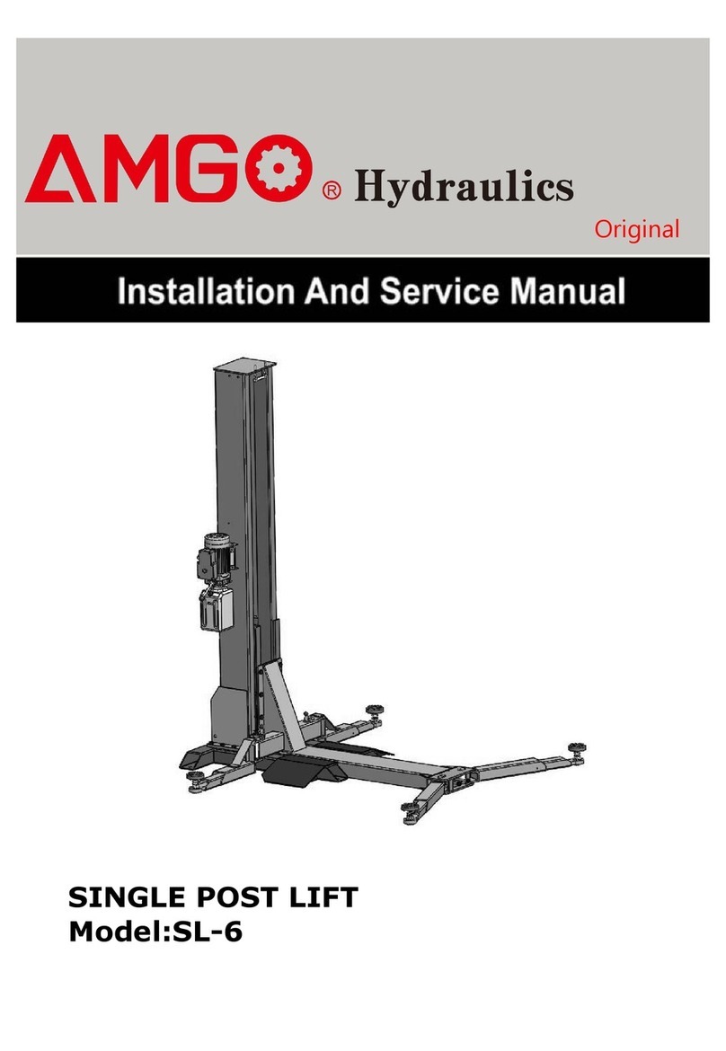
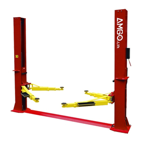
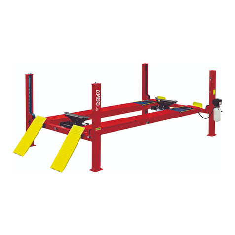
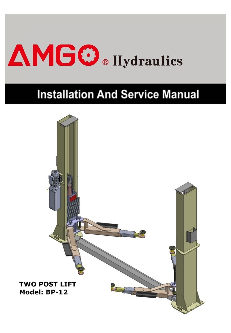
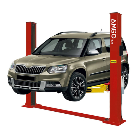
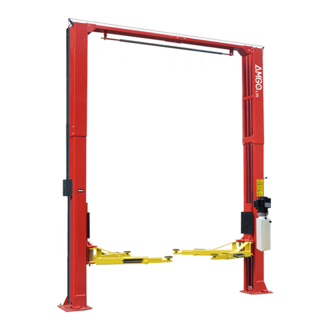
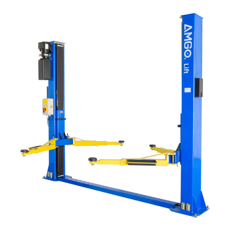
AMGO A240 Manual

TWO-POST LIFT
Model:A240
All manuals and user guides at all-guides.com
all-guides.com

CONTENTS
Product Features and Specifications ............................................1
Installation Requirement ...........................................................3
Steps of Installation………………………………………………………………………………4
Exploded View .........................................................................24
Test Run..................................................................................28
Operation Instruction ...............................................................30
Maintenance ...........................................................................30
Trouble Shooting .....................................................................31
Parts List ................................................................................32
All manuals and user guides at all-guides.com

1
I. PRODUCT FEATURES AND SPECIFICATIONS
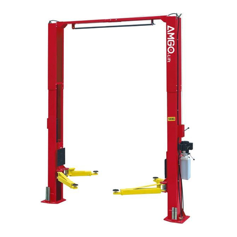
FLOORPLATE CHAIN-DRIVED TWO POST LIFT Model A240 (See Fig.1)
· Compact design
· Dual hydraulic cylinders manufactured on ANSI standards, utilizing NOK seals
· Self- lubricating UHMW Polyethylene sliders and bronze bush
· Single-point safety release, and dual safety design
· Super symmetric arms design, combined adapter
SPECIFICATIONS
Model
Style
Lifting
Capacity
Lifting
Time
Lifting Height
Overall
Height
Overall
Width
Width
Between
Columns
Minimum
Pad
Height
Motor
A240
Floorplate
Chain-drived
4.0T
9,000 lbs
45S
1825~1960mm
71 7/8”-77 3/16”
2742mm
108”
3350mm
131 7/8”
2780mm
109 1/2”
100mm
4”
3.0 HP
Fig. 1
All manuals and user guides at all-guides.com

2
Arm Swings View
2513mm
1270mm
814mm
683mm
1159mm
Fig. 2
All manuals and user guides at all-guides.com

3
II. INSTALLATION REQUIREMENT
A. TOOLS REQUIRED
Rotary Hammer Drill (Φ19)
Hammer
Level Bar
English Spanner (12")
Wrench set
(10#, 13#, 14#, 15#, 17#, 19#, 24#, 27#)
Pliers
Carpenter’s Chalk
Screw Sets
Tape Measure (7.5m)
Socket Head Wrench
(4# 5# 6#)
Fig. 3
All manuals and user guides at all-guides.com

4
B. SPECIFICATIONS OF CONCRETE (See Fig. 4)
Specifications of concrete must be adhered to the specification as following.
Failure to do so may result in lift and/or vehicle falling.
1. Concrete must be thickness 100mm minimum and without reinforcing steel bars,
and must be dried totally before the installation.
2. Concrete must be in good condition and must be of test strength 3,000psi
(210kg/cm²) minimum.
3. Floors must be level and no cracks.
C. POWER SUPPLY
The electrical source must be 2.2Kw minimum. The source cable size must be
2.5mm² and in good condition of contacting with floor.
安装地基示意图
III. STEPS OF INSTALLATION
A. Location of Installation
Check and insure the installation location (concrete, layout, space size etc.) is
suitable for lift installation.
B. Use a carpenter’s chalk line to establish installation layout of baseplate (See Fig. 5).
Concrete intensity must be 3000psi
(210Kg/cm2 ) minimum
Fig. 4
Fig. 5
Chalk line
75
All manuals and user guides at all-guides.com
all-guides.com

5
C. Check the parts before assembly.
1. Packaged lift and hydraulic power unit (See Fig. 6).
2. Move the lift aside with fork lift or hoist, and open the outer packing carefully
(See Fig. 7).
3. Take off the parts from upper and inside the column, then take out the parts box (See
Fig. 8).
4. Loose the bolts of the upper package stand, take off the upper column and remove the
package stand.
Fig. 8
Fig. 6
Fig. 7
Shipment Parts list
Floor cover
Parts box
Aluminum
nameplates
Control box
All manuals and user guides at all-guides.com

6
5. Move aside the parts and check the parts according to the shipment parts list, and
parts box list(See Fig. 9 , Fig.10).
.
7. Check the parts of the parts bag according to parts bag list (See Fig. 11).
99
Fig. 9
Fig. 11
Fig. 10
Parts box(99)
All manuals and user guides at all-guides.com

7
D. Position powerside columns
Lay down two columns on the installation site parallelly, position the powerside
column according to the actual installation site. Usually, it is suggested to install
powerside column on the front-right side from which vehicles are driven to the
lift .Then install the top plates.
(See Fig. 12).
Offside column
Car-in direction
Powerside column
Assemble topplate using
M10*35 hex bolt with
nut and lock washer
Fig. 12
All manuals and user guides at all-guides.com

8
E. Connecting the cables
1.Connect the cables under step a to f (See Fig. 13).
d. Cable pass through
the small pulley in
another column
c. Pass through the
cable from the
small pulley
a. Cable passes through
the carriage
e. Pull the cable from
bottom to top and
pass through the
cable from big pulley
f. The fitting of cable pass
through the hole of the
carriages and be screwed
with two cable nuts
b. Push the carriages higher than
chain pulley, cable pass through
the top of the carriages and pass
through the hole of the bottom
steel plate of the carriages
Fig. 13
All manuals and user guides at all-guides.com

9
2.Install cables (See Fig. 14).
Fig. 14
All manuals and user guides at all-guides.com
all-guides.com

10
F. Assembly oil hose assy.
1. Install oil hose (See Fig. 15)
Fig. 15
81
85
81A
81
79A
80
81
81
79
All manuals and user guides at all-guides.com

11
2. Push the carriages to the bottom of columns (See Fig. 16).
G. Position columns (See Fig. 17)
Check the columns plumbness with level bar, and adjusting with the shims if the
columns are not vertical.
Push the carriages to
the bottom of columns
2780mm
Cable and oil hose can not cross
Check the columns plumbness
with level bar on front and side
column
Fig. 16
Fig. 17
76
3350mm
All manuals and user guides at all-guides.com

12
H. Fix anchor bolts
1. Prepare anchor bolts (See Fig. 18).
2. Using the prescribed rotary hammer drill, and drill all the anchor holes and install the
anchor bolts. Then tighten the anchor bolts (See Fig. 19).
Note: Torque of Anchors is 117N.m.Minimum embedment of anchors is 90mm.
I. Lift the carriages up by hand and make them be locked at the same level
(See Fig. 20).
75
Fig. 18
Fig. 19
Fig. 20
90mm
All manuals and user guides at all-guides.com

13
J. Install safety device and safety cable (See Fig. 21).
NOTE: 1. Assemble safety cable from offside safety assy.
2. Pay attention to the connecting direction of safety cable.
Fig. 21
View A
View B
Safety cable
direction
All manuals and user guides at all-guides.com

14
K. Install hydraulic power unit and oil hose assy. (See Fig. 22).
Tighten all the hydraulic fittings, and fill the reservoir with hydraulic oil.
Note: In consideration of Power Unit’s durability and keep the equipment running
in the perfect condition, please use Hydraulic Oil 46#
Fig. 22
Locking the nut using 19#
ratchet spanner
3
4
2
28
200
44
84
83
All manuals and user guides at all-guides.com
all-guides.com

15
Chain cover pass
from the gap
between
carriage and
carriage
reinforce plate
Carriage reinforce plate
90
Carriage
Connecting 11# & 12#
(NC) of limit switch to
terminals 3# & 5# of
control box
L. Install control box , limit switch and chain cover . (See Fig. 23).
Fig. 23
6
90B
91
92
93
7
90A
Wire connection of limit switch
92
Note: Adjustable screw
with hook can adjust
the tauts degree of the
chain cover.
87
89
88
3#
5#
15º
64
All manuals and user guides at all-guides.com

16
96
97
95
94
M. Install electrical system
1. Connecting wire with control box (See Fig. 24).
Note: 1) Specification of wire of limit switch and hydraulic solenoid valve is 2×12
2) Wire cable for power source and motor are 4×2.52
3) Using white bobbin to wind around wire
2. Adjusting the current rating of thermal relay in control box according to the different
configurations of hydraulic power unit. In general, the electric current of thermal relay
should equal or larger than that of motor. The following table shows rated current
regulation of thermal relay in case of different hydraulic power unit.
Hydraulic power
unit
PEAK
SPX
220V
3HP
380V
3HP
415V
3HP
220V
3HP
380V
3HP
Rated current of
thermal relay
16A
12A
12A
18A
12A
Fig. 24
Connecting wire of
hydraulic solenoid valve
Connecting wire of limit
switch
Connecting wire of
motor
Connecting wire of
power
All manuals and user guides at all-guides.com

17
3. 380V Wire connection and circuit diagram
3.1 Wire connection diagram in the control box (See Fig. 26).
3.2 380V Wire connection diagram of hydraulic motor (See Fig. 27).
Motor wire (M1、M2、M3) are connected to the three wires in the motor.
Turn on the power, push UP button, if motor run but lift does not work, please
change the wires connection.
This point shows
the present rated
current value
Using cross screwdriver
to adjust rated current
value of thermal relay
Fig. 25
Power
wire
Wire of hydraulic
solenoid valve
Wire of limit switch
Wire of motor
Fig. 26
Earth wire
All manuals and user guides at all-guides.com

18
3.3 380V Circuit diagram (See Fig. 28).
Circuit diagram component list For 380V Power
Item
Name
Code
Specification
Item
Name
Code
Specification
1
Power Switch
QS
380V AC
7
Alarm Lamp
R
220V (White)
2
Fuse
FU1
25A
8
Push Button
Down
Single
3
Fuse
FU2
3A
9
Motor
M
Three phase
4
AC Contactor
KM
24V AC
10
Transformer
TC
24V AC
5
Hydraulic
Solenoid Valve
Y
24V AC
11
Limit Switch
SQ
10A
6
Push Button
UP
Single
Earth wire
M3
M2
M1
Fig. 27
Fig. 28
3 phases
All manuals and user guides at all-guides.com
Other manuals for A240
1
Table of contents
Other AMGO Lifting System manuals
Popular Lifting System manuals by other brands

Kernel
Kernel TP11KAC-D3 Operation manual

Braun
Braun NL502 Series Service manual

Genie
Genie GS-2632 operators manual with maintenance information

Manitowoc
Manitowoc 14000 Product guide

rav
rav RAV241XL Translation of the original instructions

Joerns Healthcare
Joerns Healthcare Hoyer HPL402 User instruction manual & warranty