TRAPP TR 1500 User manual
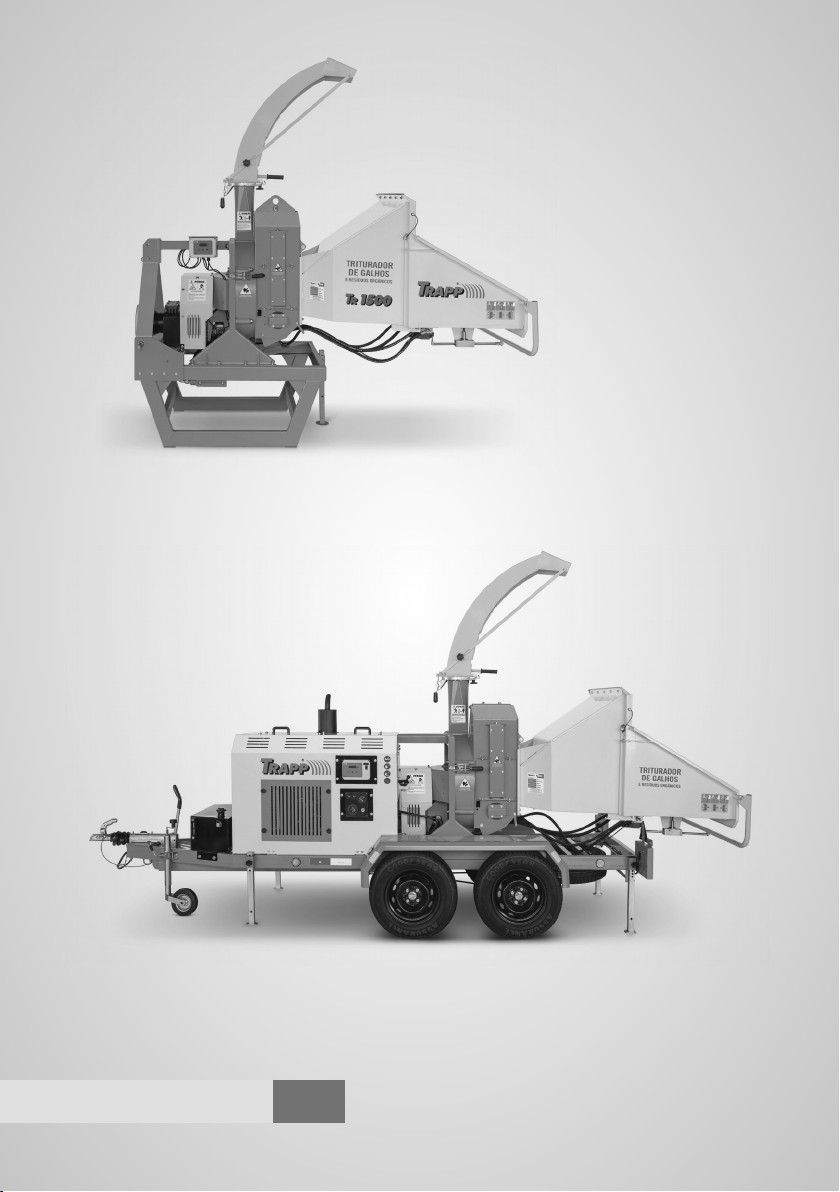
TR 1500
TR 2000
Organic Residue
Shredder
Organic Residue
Shredder
Models
TR 1500
TR 2000
Instructions Manual
TRP 1500
TRP 2000
TRP 1500
TRP 2000
3English

ENGLISH
3
www.trapp.com.br
Congratulations!
You have just acquired a quality product developed with the highest TRAPP
technology. This product will provide quickness and efciency on the jobs, with
savings and complete safety. For this, some precautions are necessary. The critical
safety measures contained in this Instructions Manual do not cover all possible
situations that may occur. The operator must understand that common sense,
attention, and precautions are not factors that can be incorporated into the product;
they must be supplied by the people that operate it and perform its due maintenance.
Important Recommendations
Caution!
Read all the instructions contained
in this manual before operating the
equipment, always observing the
safety indications and following the
instructions to prevent accidents and/
or injuries.
Read and keep these instructions.
1 - Work area
Do not operate the equipment near an
explosive atmosphere, nor wherever there are
flammable liquids, gases, and/or suspended
dust. The electrical installation of the equipment
produces sparks that may ignite flammable
liquids, gases, or suspended dust.
Keep children and spectators distant. When
the equipment is in use, all persons, especially
children, must remain at a safe distance from
the work area. The operator/user is
responsible for possible accidents that may
occur.
2 - Electrical safety
Do not expose the equipment to rain or
moisture. Install the equipment in a dry
location and protected from inclement
weather. Water inside the equipment may
damage the engine’s electrical circuits,
besides increasing the risk of electric shock
and cause the oxidation of the machine’s
structure.
3 - Personal safety
Caution!
Whenever you perform any cleaning
or maintenance operation, rst assure
that the equipment is turned off and the
blades are stationary, because the blades
continue in motion for some instants
after the equipment is shut down.
Most accidents occur while the
operator is using the machine or
during its maintenance, and are
caused by the lack of attention to the
basic safety precautions. Therefore,
it is necessary to be aware of the
potential risks of an action, paying
attention to your own actions and
their effects.

ENGLISH
4
www.trapp.com.br
Do not hold or lean yourself on the machine
during its transport; keep away at a safe
distance.
Keep alert. Remain aware of what is
happening and use common sense when you
are operating. Do not operate the equipment
when you are tired, distracted, or under the
influence of drugs, alcoholic beverages, or
medication. A moment of inattention may
result in serious injury risk.
Use safety gear such as gloves, goggles,
respiratory mask, and hearing protector,
according to the operation performed. Observe
the labels on the machine indicating the type for
safety gear required to use the shredder and
check, on page 6 of this manual, what each label
represents.
Dress appropriately. Do not wear loose clothing
or jewelry, because it may get caught on moving
parts of the equipment. If you have long hair,
keep it tied up during the job.
Prevent accidental operation.
Assure that the equipment is
disconnected from the power plug
of the tractor or, if started by a
diesel engine, turn off the key at the
starting dashboard and remove the
battery cable before performing any
maintenance on the shredder.
At no time insert any part of your
body inside the machine’s cutting
system to avoid personal damages.
Remove any object before turning on the
equipment. A tool or any other object stuck
on the moving parts of the equipment may
result in injuries.
4 - Use and precautions
Caution!
Check often if all the bolts are well
attached, especially those on the
knives and counter-knife. Always keep
the measure of the knife and counter-
knife regulated to ensure proper
performance of the shredder.
Support the machine on the ground and
lower the stabilization shoes of the machine
before turning on the shredder.
To perform the job safely, position the
machine at a site that is flat and suitable, free
from obstacles that may cause the operator to
trip upon introducing the material in the
shredder.
Do not force the equipment. Use it correctly
and for the applications described in this
manual, thus obtaining better performance
and safety in your job. Follow the indications
of use and applications on page 6 of this
manual to achieve better performance of the
shredder.
Do not use the equipment if
the “NO STRESS” system is not
operating. The equipment cannot
be controlled if this is damaged.
In this case, it must be repaired
immediately.

ENGLISH
5
www.trapp.com.br
Disconnect the battery cable,
remove the fuses, or disconnect the
power plug before performing any
adjustments or changing cutting
blades and accessories. Before
accessing the cutting system, wait
for the complete stop of the disk to
open the machine body and have
access to the shredder’s cutting
system. Such preventive measures
reduce the risk of accidental
operation of the equipment.
Carefully observe the way of introducing
the materials into the shredder; irregular
materials may hit the operator when pulled
by the feeder roll. Insert the material in the
input funnel and, when the feeding roll pulls
it, step away from the shredder.
Do not allow unacquainted persons to use
the equipment. The equipment may become
dangerous at the hands of users unacquainted
with its operation.
Check the site where you intend to release
the shredded material and regulate the
material outlet nozzle before turning on the
shredder. It is recommended that the nozzle
work in parallel to the disk so to avoid
clogging on the exit of material.
Do not use the shredder in sites that are moist
and poorly illuminated.
As soon as the disk reaches the ideal rotation,
start the feeding rolls through the drive bar
located in the feeding funnel and insert the
material you wish to shred.
Before introducing the material you wish to
shred, check the information in this manual
to see the indicated work rotation.
Be acquainted with all the triggering
commands of the shredder to know how to
act in a possible emergency stop.
Conserve your equipment. Check often if the
moving parts are fixed, if any component is
damaged or any other condition that may
affect its proper functioning. If there is a
problem, make the repair before using the
equipment. Many accidents are caused by a
lack of adequate maintenance.
Keep the cutting disk clean and with the
cutting blades clean and sharp, with the
knife and counter-knife measurement
between 3 and 4 mm.
Keep the feeding rolls clean after using the
shredder and remove the leftover material
from the protection of the smooth roll. The
accumulation of material on the feeding
rolls hampers the operation of the hydraulic
engines that trigger the feeding rolls. Keep
the machine on for a few minutes after
finishing the job; this helps in the cleaning of
the shredder.
The cutting blade keeps moving after the
equipment is shut off. Therefore, be aware
of this when performing any maintenance
or cleaning.
Never use a pressurized water jet to clean the
machine, so to not damage the electrical
components. Also do not use chemical
cleaning products, avoiding the corrosion of
the material; only use neutral detergent and
moist cloth or compressed air.
Use the equipment and accessories
according to the instructions contained in
this manual, taking into account the work
conditions and the service to be performed.
The use of the equipment for operations not
included in this manual may result in
hazardous situations.
Turn the shredder off immediately if the
nozzle is clogged, if the cutting disk is locked,
or if you notice excessive vibration of the
machine. With the machine turned off and
the disk stopped, assess the situation and
unblock the outlet nozzle or the disk and
resume the work. If the problem persists,
contact a TRAPP Assistant.

ENGLISH
6
www.trapp.com.br
Do not shred material that is not indicated for
this shredder; this results in loss of equipment
warranty. Besides these products, for any
other type of material that is not specified in
the manual, the factory must be consulted
before shredding it.
In TR 2000, watch out for the output of the
exhaust during the machine’s operation; it
produces wind and toxic smoke, and may
also cause burns due to the working
temperature.
Do not transit around the machine while it is
operating, especially in the direction in which
the outlet nozzle is releasing the material.
The material released by the nozzle may
cause serious physical damages to the
operator.
Repairs to the equipment must only be
performed by qualied professionals
and with original TRAPP parts. Always
use the services of the Authorized
TRAPP Technical Assistants. TRAPP
does not take responsibility for possible
accidents or damages that occurred due
to the use of non-original parts.
Note: Some materials contain resin, in which case the
cleaning of the machine must be performed more
often during the job to avoid the clogging of the
shredder. The recommendation is not to shred this
material when it is green since this reduces the
amount of resin.
Uses and Applications
TRAPP shredders were developed with an
efficient cutting system. The electronically-
monitored cutting disk model, cutting blades,
feeding rolls, and feeding control allow a
wide variety of materials to be shredded, with
this being a differential among other shredder
models. The list of materials that may be
shredded is presented next:
Wood trunks1) from tree pruning with
diameters up to 20 cm;
Branches with leaves and bushes;
Leaves2) and trunks of palm trees and coconut
trees;
Bamboo2);
Food-derived organic material2);
Wooden pallets and construction wood
without nails or cement residues.
Notes: 1) Wood that is very dry and of hard quality
must be fed with greater caution not to
lock or damage the cutting system.
2) These materials require some precautions
upon feeding to avoid clogging the outlet
nozzle and accumulating material in the
cutting system. Moist material may cause
clogging, while very dry material may
accumulate in the cutting system, which
needs to be cleaned more often.
Materials such as glass, metal, plastic, paper,
cardboard, styrofoam, and cement or clay
artifacts cannot be shredded. For any unspecified
materials of vegetable origin, TRAPP must be
contacted to assess the application before
shredding; damages caused by the use of non-
recommended materials lead to loss of
warranty.
Through the various types of materials that may
be shredded in TRAPP shredders, it is possible
to achieve an excellent composting result for
the enrichment of soil nutrients, cover material
for soil, use in seedbeds of gardens and
vegetable gardens, or as fuel for boilers.
Important: Certify that the result
obtained from the shredded material is
appropriate for use in composting, soil
coverage, or boiler fuel.

ENGLISH
7
www.trapp.com.br
Technical Characteristics
Model TR 1500 TR 2000
Upper hydraulic engine 622 Nm
Lower hydraulic engine 311 Nm
Disk rotation Rotation 1,600-1,150 (rpm) Maximum/Minimum
Minimum power 65 HP (tractor) 54 cv/40 kW (engine)
Minimum power for power
take-off 50 HP (with 540 rpm) Not applicable
Hydraulic system pressure 160 bar of work and a maximum of 170 bar
No Stress system Powered by 12 V - with a 10 A fuse
Activation Manual/mechanical with 3 stages
Disk diameter Ø680 mm
Number of knives 3 pieces
Total length 2,800 mm 4,850 mm
Total width 1,350 mm 1,550 mm
Total height with the nozzle 2,900 mm 2,900 mm
Cutting capacity Ø180 mm hard and dry wood, Ø200 mm green wood
Productivity 2 to 18 m3
Transmission type B-belt B39 (box/disk)
A36 (disk/pump)
V-belt BSX 35 (box/disk)
A36 (disk/pump)
Counter-knife adjustment 4 mm ±1 mm
Shredder weight 940 kg 1,450 kg
Oil in the hydraulic tank 18 liters (ISO VG68)
Oil in the gearbox 4 liters (W140)
Oil in the diesel engine
crankcase 5.5 liters with oil lter SAE 15W40
Noise 89 db(A)
ENGLISH
8
www.trapp.com.br
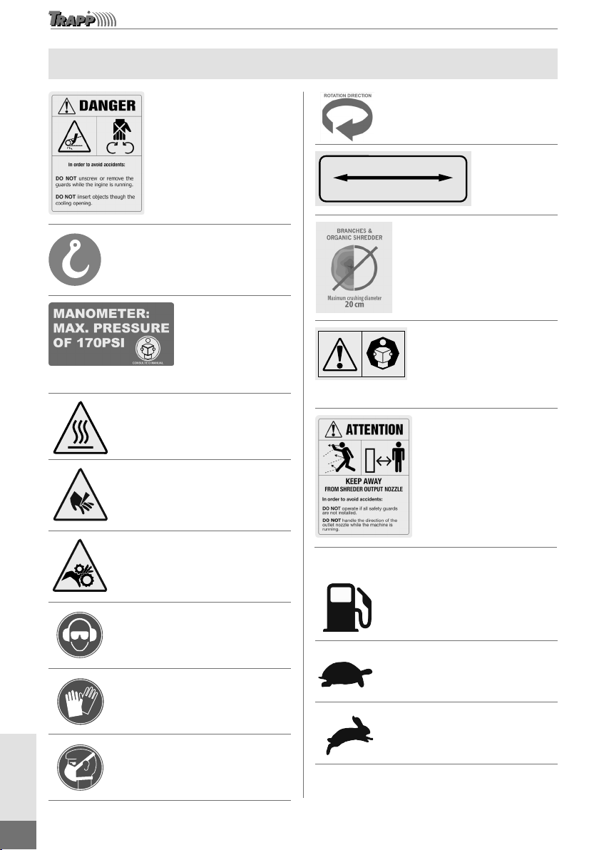
Safety Stickers
Danger of hand injuries:
Do not open or remove
the safety protections
while the machine is
operating.
Lifting point of the machine.
Manometer: maximum pressure of 170 PSI.
Superfície quente
Hot surface.
Lâminas de corte,
não introduza as mãos
Cutting blades, do not insert
hands.
Cuidado rolos de alimentação
com facas, não introduza
nenhuma parte do corpo.
Caution: feeding rolls with
knives, do not insert any body
part.
Utilizar óculos de proteção
e protetor auricular adequados
Use proper protection goggles
and hearing protector.
Utilizar luvas de
proteção adequadas
Use proper protection gloves.
Utilizar máscara de
proteção adequadas
Use proper protection mask.
Rotation direction.
Desembrear
Embreagem / Embrague / Clutch
Embrear
Embragar
Engage
Desembragar
Disengage
Clutch.
Maximum shreddable
diameter.
Caution:
Carefully read all the
instructions and safety
norms before using the
machine.
Keep away:
To avoid severe or fatal
injuries, only trigger the
shredder if there are no
people or animals close
to the machine.
Only for TR 2000
Combustível
Fuel.
Lento
Slow.
Fast.
ENGLISH
9
www.trapp.com.br
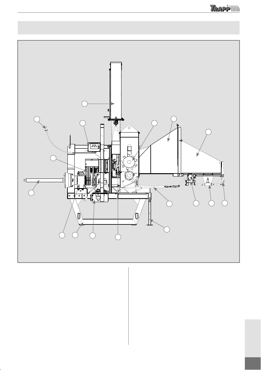
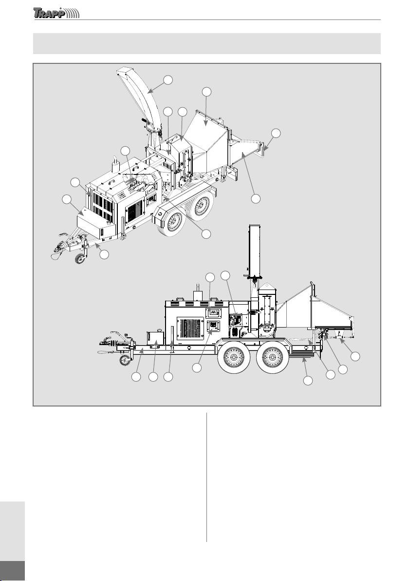
Main Components - TR 1500
11
15
16
7
5
91
10
17
14 13 12 4
86
2
3
Image merely illustrative
1. Machine base.
2. Feeding funnel lid.
3. Feeding funnel.
4. Drive bar of the feeding rolls.
5. Feeding rolls.
6. Cutting disk.
7. Set of pulleys and belts for operation.
8. Hydraulic tank.
9. Gearbox.
10. Cardan shaft.
11. Outlet nozzle.
12. Drive block of the feeding rolls.
13. Hydraulic block.
14. Hydraulic system hoses.
15. Control panel of the “NO STRESS” system.
16. Electrical outlet: 12 V.
17. Stabilizing shoe.
ENGLISH
10
www.trapp.com.br
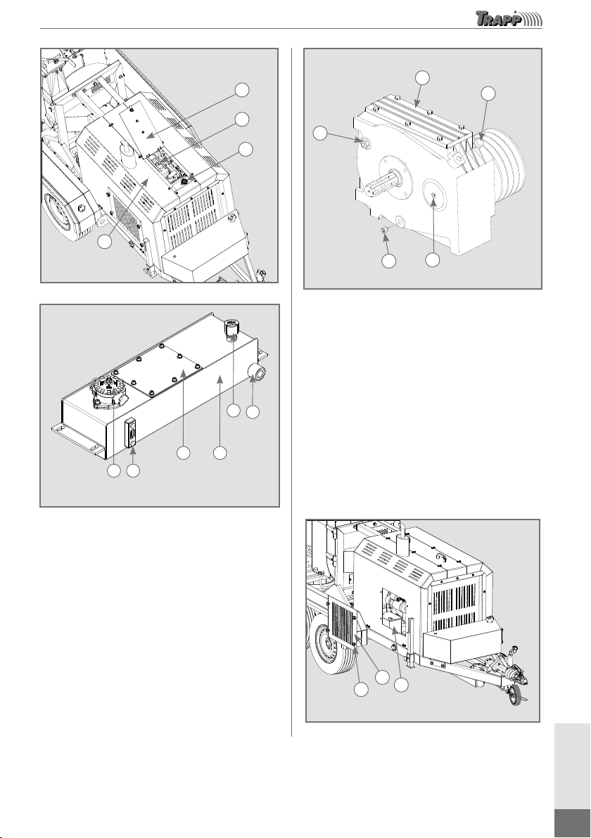
Main Components – TR 2000
6
3
2
10
1
9
8
13
4
5
7
11
1 9 17
16 15
14
12
Image merely illustrative
18
19
1. Tow.
2. Feeding funnel lid.
3. Feeding funnel.
4. Machine body where the feeding rolls are
located.
5. Machine body where the cutting disk is
located.
6. Outlet nozzle.
7. Set of pulleys and belts.
8. 54 hp engine
9. Diesel fuel tank.
10. Hydraulic tank. Control panel of the “NO
STRESS” system.
11. On/off panel and indicators of the diesel
engine.
12. Drive bar of the feeding rolls.
13. Drive block of the feeding rolls.
14. Hydraulic block.
15. Hydraulic system hoses.
16. Spare tire.
17. Stabilizing shoe.
18. Battery (located inside the fairing).
ENGLISH
11
www.trapp.com.br
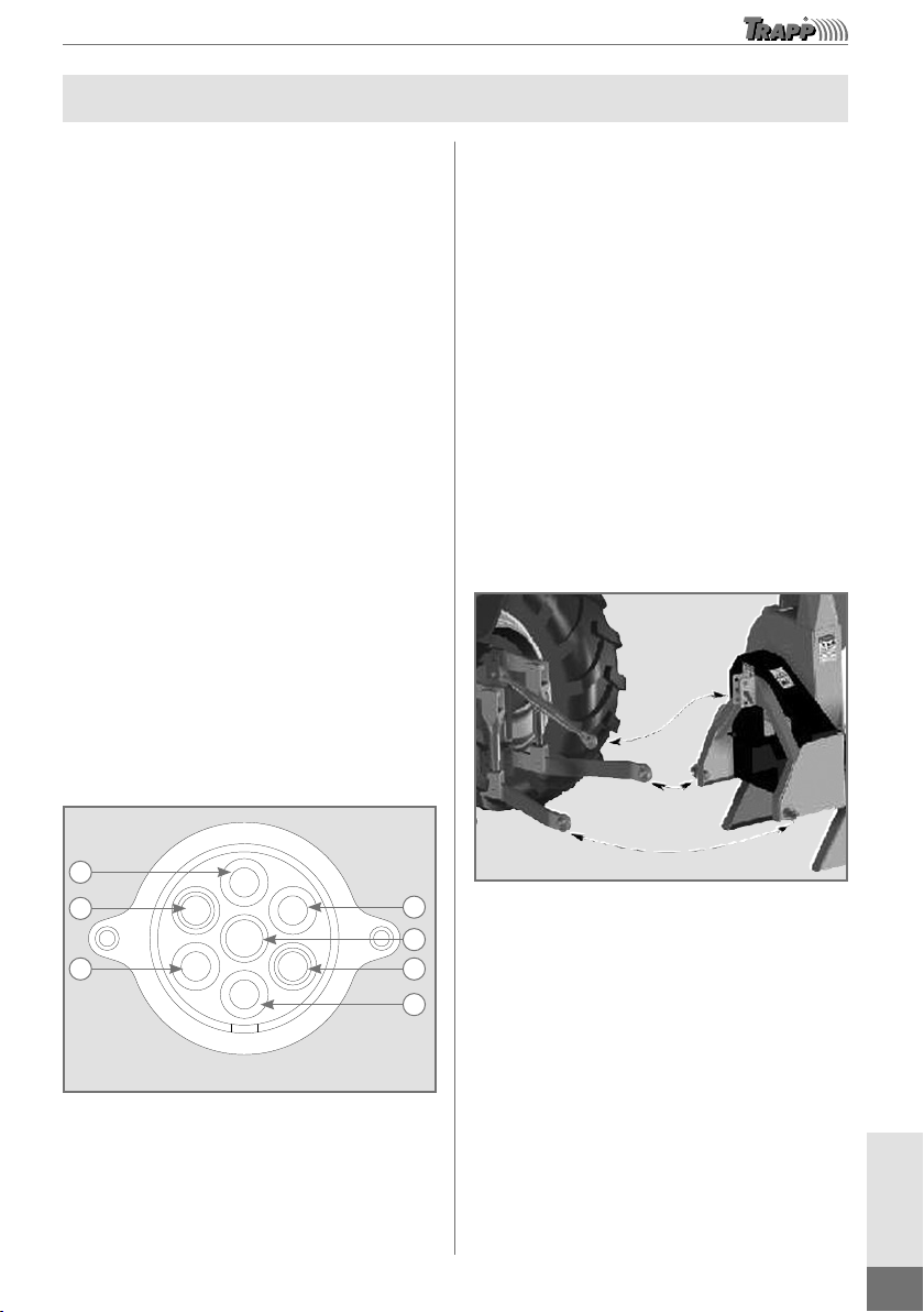
Initial Assembly and Operation Instructions
TR 1500
1. Positive.
2. Negative.
TR 200D
1. Tail light.
2. Break.
3. Left blinker.
4. Reverse light.
5. Ground.
6. Right blinker.
7. Auxiliary.
After concluding the connection of the
electrical part, check if all the functions are
correct and, then, complete the remaining
procedures for using the shredder.
1
2
3
4
13
Image merely illustrative
Figure 2
Before connecting the equipment to the
tractor, position both on flat terrain, keeping
observers and children at a distance.
Slowly approximate the shredder to the
hydraulic arms; first, connect the lower arms,
then hook it up to the upper point. The
shredder is equipped with fixing pins for
Category-II tractors.
Certify the fixation of the pins with the
corresponding safety lock; then, suspend the
shredder and lock it, lifting the stabilizing
shoe of the base of the shredder, indicated on
page 9 of this manual.
Carefully read the instructions and seek to
familiarize yourself with the controls and
proper use of the equipment.
Remember that the operator or user is
responsible for any accident or damage
involving third parties or their properties.
After removing the shredder from the
packaging, perform the assembly of the
unassembled parts to give start to the use of
the equipment.
TR 1500
For using the TR 1500, check the 12 V
electrical outlet connection with the tractor
battery, for the correct connection scheme, as
per Figure 1.
Check the oil in the gearbox and that in the
hydraulic tank. Consult the table on page 7 of
this manual. The TR 1500 shredder was
designed to be attached to a tractor equipped
with a 3-point hydraulic arm with universal
coupling, as shown in Figure 2.
Note: The warranty does not cover the burning of
electronic components, lamps, or fuses due to
incorrect installation. In doubt, contact a
professional qualified for the job.
1
2
3
4
7
6
5
Image merely illustrative
Figure 1
Note: This indication is the connection of the outlet of
the tractor or automobile.

ENGLISH
12
www.trapp.com.br
Position and lock the hydraulic arms of the
tractor with the anti-vibration lock current or
tensioners, after hitching the shredder at the
three points of the tractor. The tractor needs
to have the fixing locks to transport the
machine safely; the warranty does not cover
machine falling due to incorrect fixation.
After attaching the shredder to the tractor,
slowly lift the lifting arms with the tractor’s
hydraulic system and observe if the weight of
the machine will suspend the front wheels of
the tractor; if necessary, mount the ballasts on
the front of the tractor to balance the weight.
Cardan shaft: the Cardan shaft is a
fundamental component in the transmission
of force from the tractor to the shredder; it
must meet the mounting specifications so not
to damage the shredder during the operation
and cause excessive vibration. For the TR
1500, a 6-ridge Cardan shaft is recommended.
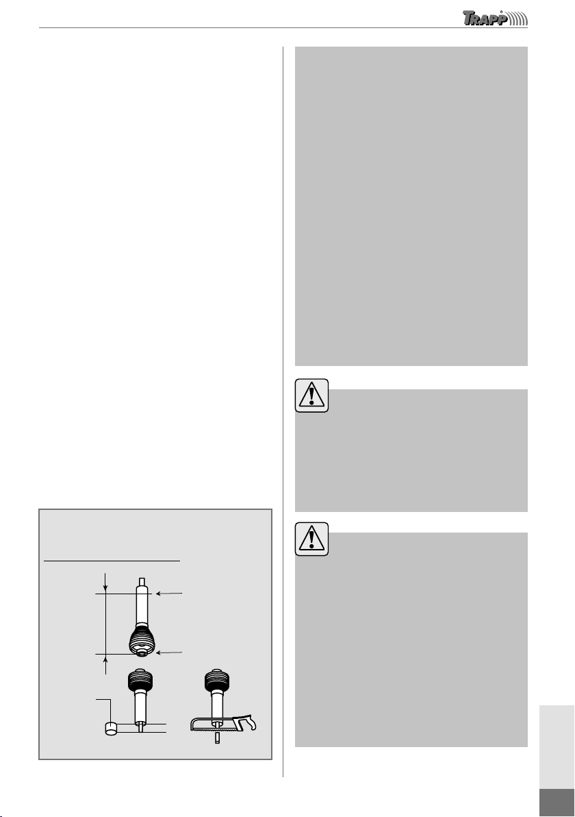
Assembly of the Cardan Shaft
Observe the indication of load capacity upon
suspending the TR 1500 on the hydraulic
system of the tractor; check the weight of the
machine on page 7 and consult the tractor
manufacturer.
To obtain a proper assembly between the
tractor’s power take-off and the machine, the
Cardan shaft must have a superposition of at
least 1/3 of its length to meet the safety norms.
The recommendation for the working
inclination of the Cardan shaft is of at least
15°; adjust the inclination angle by regulating
the tractor’s hydraulic system. If the tractor
model allows and the angle is compatible,
keep the TR 1500 supported on the ground
during the job to achieve better access to the
feeding funnel. If the height of the machine
gets uncomfortable to feed the funnel due to
the inclination, position the tractor in terrain
with elevations to facilitate the access to the
feeding funnel and maintain the equipment
supported on the ground.
Note: When suspending the TR 1500
with the tractor’s hydraulic system,
check the maximum inclination allowed
of the Cardan shaft assembled on the
machine and the power take-off of the
tractor.
Exceeding the inclination may damage
the equipment and produce excessive
vibration on the operating shredder.
To perform maneuvers with TR 1500
assembled onto the tractor, disconnect
the Cardan shaft from the machine.
Upon positioning the machine on the
ideal working site, mount the Cardan
shaft again and check its inclination,
adjusting if necessary.
To assemble the Cardan shaft, remove it from the
package and separate the male from the female.
To obtain the measure to cut the Cardan shaft,
mount the machine at the 3 points of the tractor,
align the axes of the power take-off of the tractor
and of the machine, and check the distance bet-
ween the ends of the axes.
The measure found between the axes of the
power take-off must be divided by 1.3. The
value of this division will indicate
measurement A; mark the Cardan shaft with
measurement A and cut the surplus, as shown
in Figure 3. At the marked position, cut the
excess of the male and female Cardan with a
saw bow with a 24-tooth steel-cutting blade
or with a cutting disk, using protective gear.
After concluding the complete cut, mark the
plastic protection of the male and female
Cardan and remove 3 centimeters of the
plastic protection only, cutting with a saw,
leaving the Cardan shaft with the tip exposed,
as indicated in Figure 3.
After performing the cutting procedure,
remove the burr from the cut pieces, discard
the cut material, and mount the Cardan shaft
on the machine. If necessary, release the
machine that is attached to the tractor so you
will have room to assemble the Cardan shaft.
Fit the male and female parts of the Cardan
shaft and mount the female side on the axis of
the power take-off of the TR 1500, then fit the
male Cardan shaft on the axis of the power
ENGLISH
13
www.trapp.com.br
take-off of the tractor until you hear a click,
showing that it is in the correct fitting position
on both sides.
After the assembly and adjustment of the
protection chains, move the inclination of the
tractor’s hydraulic system and check if there is
slack between the male and female Cardan,
positioning the machine at the recommended
tilt of at most 15°.
Fix the retention chains of the protection. The
ideal functioning condition is obtained with the
chain positioned radially relative to the
transmission. Regulate the length of the chains to
allow the articulation of the transmission in any
condition of work, transport, and maneuver.
Certify that the chains do not wrap around the
transmission due to excessive size. Before
starting the job, check the rotation of the power
take-off; it must not exceed 540 rpm. Check also
the inclination and if the machine is supported
on the ground to avoid damages to the shredder
and cause the warranty loss.
Observe, as the machine moves, if the male
and female Cardan shafts get close enough to
the point of touching; if this occurs, turn off the
power take-off immediately. Dismantle the
male and female Cardan shafts and perform the
cutting again so to leave slack of at least 1 to 2
centimeters between the ends of the Cardan
shaft to initiate the functioning of the shredder
following the operating instructions.
Image merely illustrative
Cut out
3 cm of
the plastic
protection
Measure A
The measure of the cut.
Dividing the measurement found between axes by 1.3 will
supply the measure to cut the Cardan shaft.
Measure from the
extremity of the
cardan shaft
Cutting line
The measure between Cardan shafts
1.3 = Measure A
Figure 3
Note: The cut pieces of the massive
and tubular parts of the Cardan must
have the same length.
Do not stop the rotation of the power
take-off of the tractor suddenly unless
for safety purposes. The abrupt
stop may damage the transmission
system of the equipment.
Do not use the chains to transport
or support the Cardan transmission.
It is not recommended to work
with the male and female Cardan
shafts without slack since this may
damage the power take-off axes of
the tractor and shredder. To perform
maneuvers, remove one of the parts
of the cardan shaft.
Caution!
These operations must only be
performed on appropriate terrain
and only after having stopped the
tractor, turned off the power take-
off, and pulled the parking brake.
Caution!
If necessary, lift the machine from
the ground. However, for the safety
of all, put it over support, avoiding
any accident that may be caused by
a possible sudden fall.
Before removing the shredder from
the 3-point hitch of the tractor,
position the stabilizer shoe of the
base as indicated on page 9 of this
manual.
ENGLISH
14
www.trapp.com.br
TR 2000
The TR 2000 shredder was designed to be
triggered by a diesel engine and with a utility
trailer homologated by the Department of
Transportation (Detran) to transport the
equipment in urban roads, according to each
city’s legislation.
Before hooking up the utility trailer with the
TR 2000 to any automobile, check the
indication of load capacity of the automobile’s
support and compare if it is compatible with
the weight of the machine. Before connecting
the trailer to an automobile, position both on
flat terrain, keeping observers and children
away. Before turning on the 12 V outlet of the
carriage to an automobile, check the electrical
outlet connection and the wiring scheme;
consult Figure 1 on page 11 for the correct
wiring scheme. Damages caused by incorrect
connections are not covered by warranty.
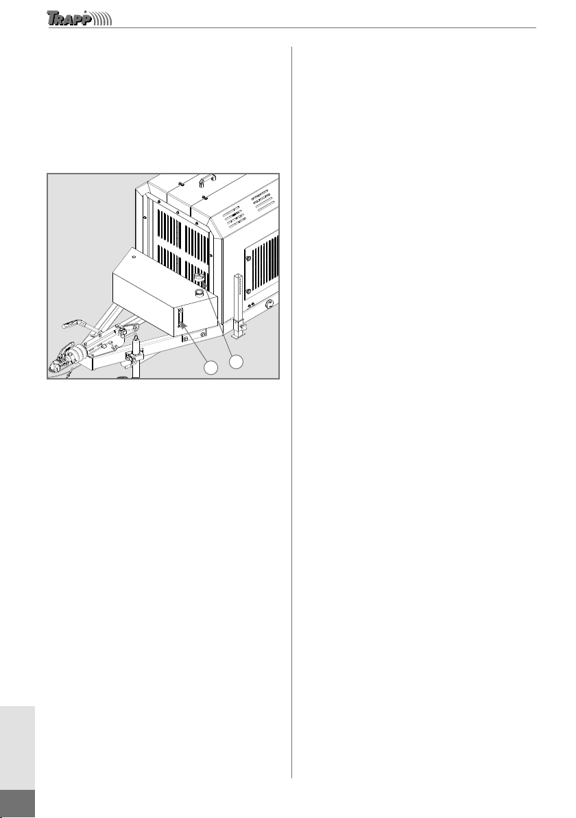
After hooking up the utility trailer to the
automobile and securing the safety cables
and chains, suspend the support wheel (1) by
turning the upper gauntlet; to lift the entire
set, release the side gauntlet and lift at most
for transport, then secure it again. Then,
suspend the stabilizer shoes (2) and retighten
its screws; release the stationary brake (3) as
indicated in Figure 4 and test the brake light
and blinkers.
Before transporting the equipment, close the
material input funnel lid (4) using the lock (5)
to secure it, and remove the material outlet
nozzle (6) by loosening the screws (7),
washers (8), and the lock (9) as indicated in
Figure 4; check if the protections and
accessories of the TR 2000 are well fixed.
After transporting the TR 2000 at the worksite,
place it on a flat position and, if you wish to
work with the utility trailer disconnected
from the automobile, adjust the support
wheel and the stabilizer shoes leaving the
machine aligned, then trigger the stationary
brake and disengage the trailer from the
automobile.
Assemble the material outlet nozzle and
direct it towards the desired position; check
if, with the transport of the machine, all its
parts are well fixed before operating the
shredder.
Image merely illustrative
2
1
3
2
4
5
7
9
8
6
Figure 4
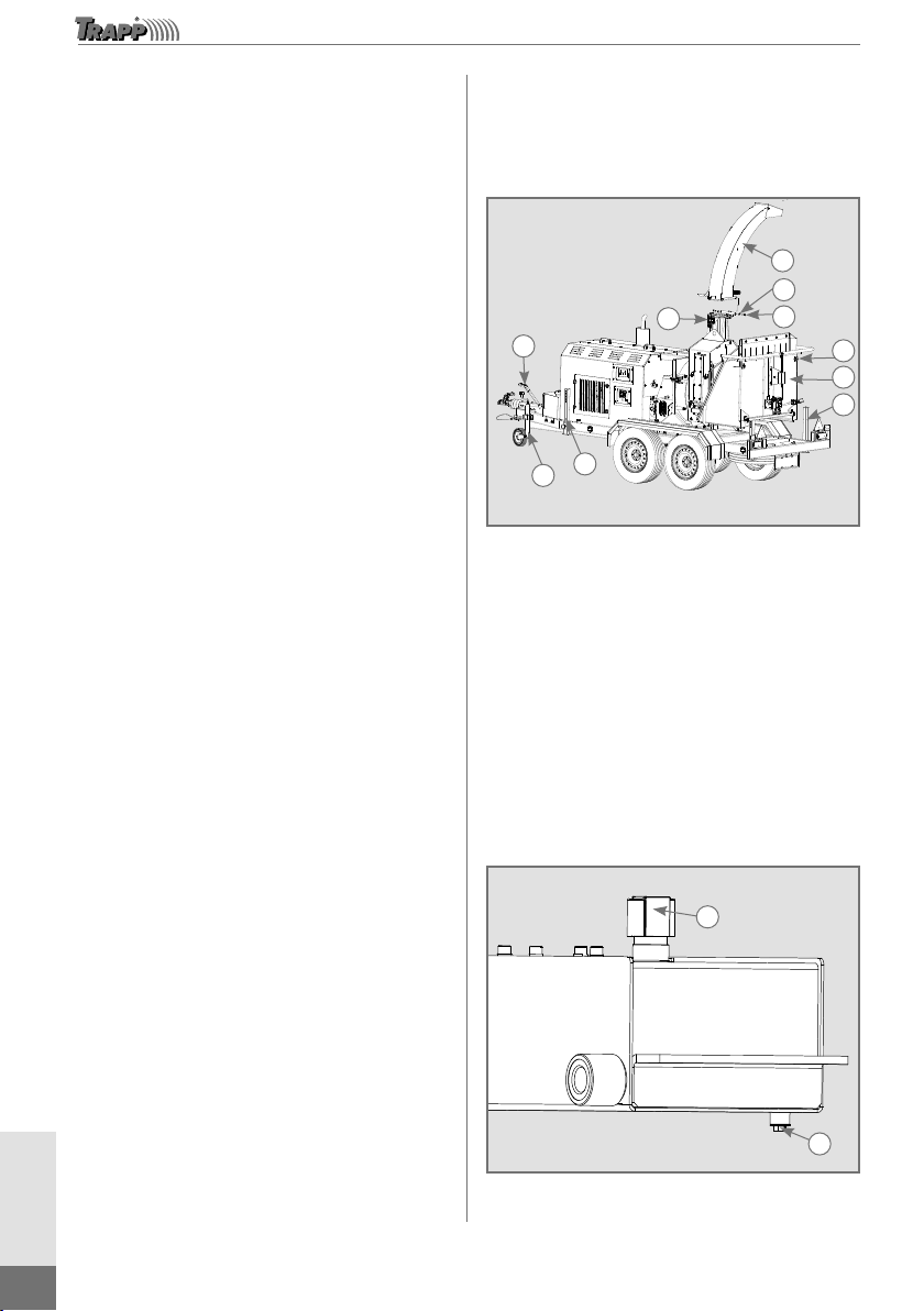
Hydraulic Reservoir Oil Change
To change the hydraulic reservoir oil, remove
the oil input lid (1), position a container with
capacity to support the amount of oil in the
reservoir below the drain plug with the drain
screw (2), remove the drain screw (2) located on
the lower part of the tank and wait for all the oil
to drain. After all the oil has been drained, fix the
drain screw again (2) and complete with 18
liters of VG68 oil; check the level and then
close the oil input lid (1).
Image merely illustrative 2
1

ENGLISH
15
www.trapp.com.br
Operation Instructions
Operator requisites:
Every operator that uses the equipment
must be competent and necessarily
meet the following characteristics:
O Physical: Have good eyesight,
coordination, and capacity to perform
all the necessary functions for using
the machine.
O Mental: Have the capacity of
understanding and applying the safety
norms and precautions established
in this instruction manual. The user
must be alert for their own safety and
that of other persons, as well as to
avoid damage to the equipment.
O Training: The user must have read,
studied, and understood this manual,
graphics, and schemes. They must
be qualied and trained for use or
maintenance of the equipment,
signing the back of the manual after
becoming acquainted with all the
instructions of operation and safety of
the machine.
Checklist
Before putting the shredder into operation,
one must check:
O The use of adequate apparel and footwear,
as well as safety gear such as protective
goggles, respiratory mask, hearing
protector, and gloves.
O If there is nothing locking the cutting disk.
O If there are no tools or objects inside or on
top of the equipment, especially inside the
feeding funnel.
O If the rotation direction is correct.
O If there are no people or objects near the
pulleys and belts or around the machine.
Spectators must be at a radius of 30 m
away from the machine.
O If the Cardan shaft is duly fitted both on
the shredder as the tractor’s power take-off
(TR 1500).
O If the hydraulic hoses are all duly fixed
and with no leakages.
O If the outlet nozzle is duly fixed and
directed towards a safe location.
O If the hydraulic tank and gearbox are duly
filled up with the indicated amount of oil
(TR 1500).
O If the hydraulic tank, fuel tank, radiator,
and diesel engine crankcase are filled up
with the amounts of fluid indicated in the
manual (TR 2000).
O Only shred woods and plants in the
dimensions of the machine’s capacity.
O Certify that there is enough fuel in the
tractor and in the fuel tank of TR 2000 to
avoid a forced stop. Only fuel TR 2000
with standard Diesel.
O Only use the shredder in safe conditions
and ventilated and well-lit places.

ENGLISH
16
www.trapp.com.br
Note: After checking the items above
and with the equipment being duly
prepared for the job, start the engine
(connecting the tractor to TR 1500 or
turning on the diesel engine for TR
2000). Wait until the maximum rotation
is reached, then wait approximately 5
minutes for the hydraulic oil to reach
the working temperature. Never start
or leave running a diesel or gasoline
combustion engine in closed or
unventilated environments. The gas
expelled by the exhaust contains
carbon monoxide, an odorless and
lethal gas.
O Avoid exposing the shredder to a location
with much sun intensity to not heat the
machine in some parts which already
reach high temperatures. To protect your
hands, use gloves, and protect other body
parts to prevent burns.
O Avoid inadequate work postures or effort
during the use of the shredder, following
the use instructions of the shredder.
8. .
Shredder Utilization
Caution!
Read all the instructions contained
in this manual before operating the
equipment, always observing the
safety indications and following the
instructions to prevent accidents and/
or injuries.
Check if all the fluids of the shredder, as per
the model table on page 7, have been
supplied and are in accordance with the
following specifications:
TR 1500
O The oil in the transmission box;
O The oil in the hydraulic tank.
TR 2000
O The oil in the hydraulic tank;
O The oil in the engine crankcase;
O The water in the engine’s radiator;
O The diesel in the fuel tank.
For the instructions for filling the diesel
engine fluids, open the upper protection (1)
of the cowl (2) that gives access to the radiator
lid (3) and the crankcase oil lid (4); add water
to the radiator, if necessary, and oil to the
crankcase, following the recommendations
in the engine manual; then, close the upper
protection again and certify that you have
closed the radiator and oil input lids, see
Figure 5.
To insert oil in the hydraulic tank (1) in TR
2000 and TR 1500, proceed as follows:
O Remove the oil input lid (6) and, with the
aid of a funnel, supply 18 liters of VG68
oil. Check the oil level through the
viewfinder (5) and, after filling up, check if
there are leaks at the hose outlet (4). If you
need to clean, open the lid (2) by
loosening the screws, noting that, after
opening the lid, it must be glued with
gasket glue to avoid leakages. On the
return filter (3), there is a saturation
indicator that turns red when it must be
changed, as per figure 6; for changing,
consult a TRAPP assistant.
ENGLISH
17
www.trapp.com.br
Image merely
illustrative
4
2
1
3
Figure 5
4
6
12
3 5
Image merely illustrative
Figure 6
In TR 1500, to insert oil in the gearbox,
proceed as follows:
O Open the lid (4) and add 4 liters of W140
oil, checking the level through the
viewfinder (1). If maintenance or cleaning
is necessary, open the lid (4) and, if you
need to remove the oil, open the drain
plug (3). The screw (5) may be removed
when necessary for maintenance; the
gearbox has a pressure relief valve (2), as
per Figure 7.
Image merely illustrative
35
2
4
1
Figure 7
Note:
The radiator of the TR 2000 is supplied with
water; just check the water level and complete, if
necessary.
For TR 2000, to connect the battery (1),
proceed as follows:
O Open the lid (2) for accessing the engine,
loosening the fixing knobs (3) and connect
the negative and positive cables at their
respective places. After fixing the cables,
certify that the battery is well set, assemble
the lid (2) again using the knobs (3), which
must be quite tight, as per Figure 8.
Image merely illustrative
3
21
Figure 8
ENGLISH
18
www.trapp.com.br
For TR 2000, to supply the fuel tank, proceed
as follows:
O Open the lid (1) using the key and check
the amount through the viewfinder (2), as
per Figure 9. Fuel only with standard
diesel. After fueling, close the lid and check
if there is no fuel leak or spillage before
starting the engine. Capacity: 45 liters.
Image merely
illustrative
21
Figure 9
For TR 1500, the electrical part of the
machine is fed by the tractor’s battery. In this
case, after checking the connection between
the cables, connect the plug of the “NO
STRESS” panel to the power outlet of the
tractor, 12 V tension.
For TR 2000, the diesel engine has a manual
pump to eject fuel and requires “bleeding the
diesel” when turning on for the first time. For
this, consult the engine’s manual.
In TR 2000, as soon as the engine runs, let it
warm up for about 5 minutes, turn on the
“NO STRESS” panel, then engage the clutch
to tension the disk belt. As soon as it is
tensioned, accelerate the engine until the
panel indicates the rotation of 1,500 rpm.
For TR 1500, as soon as the tractor is turned
on, engage its power take-off at low rotation.
As soon as the Cardan shaft begins rotating,
turn on the “NO STRESS” panel and
accelerate the tractor until reaching the
rotation of 1,450 rpm on the machine’s panel
or 540 rpm on the tractor.
When the equipment is in use, all persons,
especially children, must remain at a safe
distance from the work area. The operator/
user is responsible for possible accidents that
may occur.
Never let anyone touch the machine while it
is being used or transported.
When using the equipment, only one person
must give instructions and perform signals
related to the movement of the load.
Tips for good operation
The opening of the input funnel next to the
feeding roll is of 20 cm; if the material to be
shredded exceeds this measure, it may lock
the material input. Woods with irregular
measures must be selected and have their
size adjusted before being inserted into the
feeding funnel.
Organic materials derived from food leftovers
must be inserted into the machine
accompanied by branches and leaves to
facilitate the shredding and the entry into the
feeding roll.
Do not hold the introduced material after the
feeding roll pulls it. When the material begins
being pulled, back away from the feeding
funnel since irregular woods or branches
might produce unexpected movements
striking the operator and causing severe
accidents.
Do not introduce material with over 2 m of
length into the feeding funnel, since it may
damage the shredder or cause physical
damages to the operator. If necessary, cut the
material into parts before inserting it into the
feeding funnel.
Material with length lower than 40 cm must
be inserted into the feeding roll right after
more lengthy material to ease the entry of the
material into the feeding roll.

ENGLISH
19
www.trapp.com.br
Materials with diameters above 15 cm must
be inserted in the feeding roll right after
materials with smaller diameters that are
already being shredded to facilitate the
opening of the feeding roll. If necessary, the
feeding roll’s input opening may be adjusted
to aid the entry of materials with varying
measures.
To achieve proper operation of the cutting
system and not lock the cutting disk or clog
the material outlet nozzle, regulate the speed
of the feeding rolls by adjusting the knob (1)
in the input funnel, monitoring the system
pressure with the manometer (2) as per Figure
10, and proceed with the following
recommendations:
O Assess and separate the material to be
shredded. Set aside materials with
diameters over 16 cm, which require a
differentiated adjustment to obtain better
shredder performance and avoid constant
stops due to clogging or locked disk. For
this purpose, turn the knob to the negative
sign (-) to reduce the feeding roll speed;
O Materials with diameters smaller than 16
cm and with more leaves may be shredded
with a higher feeding speed, thus
achieving better productivity. For this
purpose, turn the knob to the positive sign
(+) to increase the feeding roll speed;
O Fibrous materials such as palm and
coconut tree leaves, as well as eucalypts
bark, tend to accumulate easily on the
disk, so mix them with drier woods, and
this will help the self-cleaning of the
cutting set;
O Change the programming of the “NO
STRESS” panel to shred wood with
diameters over 16 cm; regulate the
stopping rotation to 1,250 rpm, as per the
programming instruction in this manual;
O Woods with diameters smaller than 16 cm
may be shredded with the regulation of
the rotation on the panel at 1,150 rpm, as
when it left the factory.
Image merely illustrative
2
1
Figure 10
Image merely illustrative
Figure 11
The knob located at the entry of the feeding
funnel has the function of altering the rotation
of the feeding rolls.
To obtain a reference and be able to regulate
the rotation of the feeding rolls, observe the
pressure indication on the manometer
positioned on the outside of the funnel.
When the pressure on the manometer
indicates 170 psi, this means that the rotation
of the feeding rolls is already at the smallest
rotation possible; this adjustment applies to
wood with diameters larger than 16 cm.

ENGLISH
20
www.trapp.com.br
When the pressure indicates 50 psi, the
rotation of the feeding rolls is at the ideal
rotation for wood or branches with leaves
with diameters smaller than 16 cm and other
materials.
The panel with the “NO STRESS” system
monitors the worked hours and the rotation
of the cutting disk, and releases or blocks the
rotation of the feeding rolls; the feeding rolls
do not run if the panel is not on.
The panel has quite sensitive buttons for
programming; the programming of the
rotation may be changed to ensure the
control on the feeding of the material to the
disk, ensure the safety of the cutting set, and
improve the efficiency of the shredder for
various applications.
Assess the type of material to be shredded;
some materials need to be shredded
separately, and others may be mixed for
better performance;
Wood with diameters below or above 16 cm
must be shredded with differentiated
programming. For this, proceed as follows:
1. Simultaneously press the 3 keys
(F ▼▲), try multiple times until the panel
shows the programmed rotations of 1,650
(maximum) and 1,150 (minimum);
2. When the light starts blinking, keep pressing
the F key and release the two other keys
(▼▲) the panel will show the programmed
rotation; never alter the rotation without
consulting the manual;
3. Adjust the first rotation (minimum) to 1,250
rpm by pressing the keys (▼▲) of the panel
to increase or decrease the numbering; this
programming is for wood with diameters
above 16 cm. Do the same for wood with
diameters below 16 cm, programming the
rotation to 1,150 rpm. When finished, release
the F key;
4. To change the information on the panel
display and show the hours worked, press
the F key. Observe Figure 11, which shows
the panel and the programming buttons;
The maximum rotation of 1,600 rpm must
not be changed; in case you have difficulty
performing the programming, contact a
TRAPP Assistant.
Remove foreign bodies such as pieces of
metal, glass, or rocks before turning the
machine on.
Turn on the shredder and wait for it to reach
the maximum rotation to insert materials to
be shredded.
Assess the pressure of the hydraulic system
through the manometer located at the feeding
funnel. The pressure indicated when the rolls
are running must not exceed 170 psi; if the
pressure exceeds this value and the roll is not
turning, consult the closest TRAPP Technical
Assistance.
In case the shredder has been idle
for a long time, some adjustments
may be necessary to the hydraulic
system or the diesel engine, such as
the bleeding of the injector nozzles;
if necessary, consult the closest
TRAPP Technical Assistance.
TRAPP does not take responsibility for
occurrences and damages caused by the lack
of compliance with the instructions contained
in this manual.
After defining the programming of the ideal
work rotation, move the drive bar of the
feeding rolls, located at the feeding funnel, to
test the three stages: advance, still, and retreat,
as per Figure 12.
This manual suits for next models
1
Table of contents
Other TRAPP Farm Equipment manuals


Popular Farm Equipment manuals by other brands

Schaffert
Schaffert Rebounder Mounting instructions

Stocks AG
Stocks AG Fan Jet Pro Plus 65 Original Operating Manual and parts list

Cumberland
Cumberland Integra Feed-Link Installation and operation manual

BROWN
BROWN BDHP-1250 Owner's/operator's manual

Molon
Molon BCS operating instructions

Vaderstad
Vaderstad Rapid Series instructions


