Trelawny TFP260 User manual

www.trelawny.co.ukwww.trelawny.co.uk
TFP260 Floor Scarier
operations and maintenance manual

PAGE 2
TFP260 FLOOR PLANER
CONTENTS
Introduction ................................................................................................................................................................ 3
Declaration of Conformity..................................................................................................................................... 4
Foreword ...................................................................................................................................................................... 7
General Information ................................................................................................................................................ 7
Safety ............................................................................................................................................................................. 7
Risk of Hand Arm Vibration .................................................................................................................................. 8
Cutter Types & Applications................................................................................................................................. 8
Pre Start Checks (Daily) ......................................................................................................................................... 9
Starting - Petrol Engines ....................................................................................................................................... 9
Starting - Electric Motors ..................................................................................................................................... 10
Machine Operation ................................................................................................................................................... 10
Shut Down ................................................................................................................................................................... 10
Belt Removal & Installation.................................................................................................................................. 11
Servicing ....................................................................................................................................................................... 11
Exploded Diagrams & Parts List ....................................................................................................................... 12
Technical Specications ....................................................................................................................................... 15
Trouble Shooting ...................................................................................................................................................... 16

www.trelawny.co.uk
INTRODUCTION
Your new Trelawny SPT power tool will more than satisfy your expectations. It has been manufactured under
stringent Trelawny SPT Quality Standards to meet superior performance criteria. You will nd your new tool easy
and safe to operate, and, with proper care, it will give you many years of dependable service.
WARNING
Carefully read through these original instructions before using your new TRELAWNY power
tool. Take special care to read the warnings. Your TRELAWNY power tool has many features
that will make your job faster and easier. Safety, performance, and dependability have been
given top priority in the development of this tool, making it easy to maintain and operate.
ENVIRONMENTAL PROTECTION
The machine, accessories and packaging should be sorted for environmentally friendly
recycling. The plastic components are labelled for categorised recycling.
DISPOSAL
Waste products should not be disposed of with household waste. Please recycle where
facilities exist. Check with your local authority or retailer for recycling advice.

PAGE 4
TFP260 FLOOR PLANER
www.trelawny.co.uk

PAGE 6
TFP260 FLOOR PLANER
www.trelawny.co.uk 5
TFP200
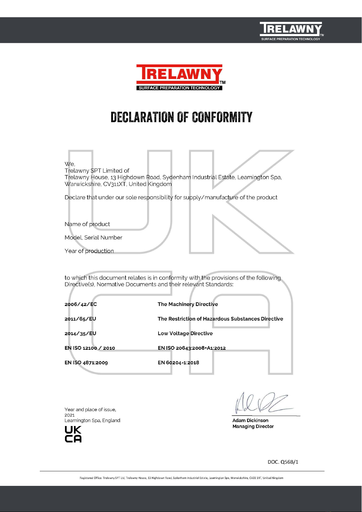
DECLARATION OF CONFORMITY
CZ Prohlášenl o přizpüsobení
My, společnost Trelawny SPT Limited
podajemy daňové přiznáni. že výrobek a dodávka výrobku
název výrobku
Model, výrobni čislo
Rok výroby
Pro které se průkaz týkajici, je přizpůsobeni s zásoby od následujici přikazov a jejich pohotovostni:
98/37/EC Přikaz soustroji
73/23/EC Přikaz nizkého napéti (upotřebitelne jediné do výrobku použiti elektnckej energie)
LT ATITIKTIES DEKLARACIJA’
Mes, Trelawny SPT Limite
Prisiimdami visą atsakomybę deklaruojame, kad tiekiamas / gaminamas produktas
Produkto pavadinimas
Modelis, serijos numeris
Pagaminimo
Kuriam taikoma ši deklaracija, atitinka šių direktyvų, norminių aktų ir su jais susijusių. standartų reikalavimus:
98/37/EC ļtrangos direktyva
73/23/EC Zemos įtampos direktyva (taikoma tik elektriniams įrengimams)
DE Ubereinstimmungserklarung
Wir, Trelawny SPT Limited
erklaren, dass unter unserer alleinigen Verantwortung fur die Lieferung und Herstellung des Produktes
Name des Produktes
Model, Seriennummer
Jahr der Herstellung
auf welches sich dieses Dokument bezieht. stimmt mit den Vorgaben der folgenden Direktive, normativen Dokumente und deren
jeweiligen Masstabe ein:
98/71/EC Maschineriedirektive
73/23/EC Niederspannungsdirektive (nur zutreffend auf Produkte, die Strom benutzen)
MT DIKJARAZZJONI TA KONFORMITA
Aħna, Trelawny SPT Limited
Niddikjaraw li aħna responsabbli kompletament għal provista / manifattura tal-prodott hawn 1msemmi:
lsem ll-Prodott
Mudell, Serial number
Sena Ia 'produzzjoni
Dan id-dokument magħmul għal prodott imsemmi hawn fuq, li huwa skond il-provizjonijiet imsemmija d-dokumenti tal-klassi tax-
xogħol:
98/37/EC Machinery Directive
73/23/EC Low Voltage Directive (tapplika biss għal prodotti li jaħdmu bl-eletrkiu)
DK Erklæring om overensstemmelse
Vi, Trelawny SPT Limited
Erklærer hermed at under vores ene forhandling ansvar for vores forhandling/produktion af produktet
Produkt navn
Model, serie nummer
Produktionsár
For hvilket delle dokument referer, at deler i overensstemmelse med bestemmelser af følgende direktiver, normative dokumenter
og deres relevante standart:
98/37/EC Machinery directive
73/23/EC Low voltage directive
NL EENVORMIGHEIDSVERKLARING
Wij. Trelawny SPT Limited
Verklaren dat wij de volledige verantwoordelijkheid dragen voor het leveren/fabriceren van het volgende product:
Naam van het product
Type, Serienummer
Productiejaar
En verklaren dat het product waarnaar dit document verwijst eenvormig is met de voorzieningen van de volgende Richtlijn(en),
Normatieve Documenten en hun relevante Standaarden:
98/37/CE MACHINERICHTLIJN
73/23/CE LAAGSPANNINGSRICHTLIJN (uitsluitend van toepassing bij producten die elektrische stroom gebruiken)
EE TOOTE VASTAVUSE DEKLARATSIOON
Meie, Trelawny SPT Limited
Deklareerime, et vastutame jägmise varustuse/toote müügi eest
Toote nimetus
Mudel, Seeria number
Aasta toodangu
Antud dokument töendab toote vastavust järgmistele direktiivi(de)le, normatiivaktidele ja nendega samaväärsetele standarditele:
98/37/EC MASINA DIREKTIIVID
73/23/EC MADALPINGE DIREKTIIVID (Kohandatakse vaid toodetele, mis kasutavad elektrivoolu
PL Deklaracja Zgodnosci
My, Firma Trelawny SPT Limited.
oświadczamy w naszej odpowiedzialności, ze produkcja i dostawa urzctdzenia
Nazwa produkta
Model, numer seryjny
Rok produkcji
do którego ten dokument należy, jest zgodne z klauzulami nastąpujacych zarządzen i ich istotnych standartów:
98/37/EC Zarządzenie mechaniczne
73/23/EC Zarządzenie niskiego napięcia elektrycznego (Zastosowanie tylko przy urządzeniach elektrycznoych)
ES Declaración de Conformidad
Nosotros, Trelawny SPT Limited
Declaramos que bajo nuestra completa responsabilidad de Ia fabricación/suministro del producto
Nombre del Producto
Modelo, No de Serie
Año de producción
A quién este documento se refiere, está de acuerdo con lo relacionado en Ia Directriz, Normativa Documentada y sus relevantes
standards:
98/37/EC Directorio de Maquinaria
73/23/EC Directorio de Bajo Voltaje (Aplicable solamente a productos que funcionen con electricidad)
PT DECLARAÇÄO DE CONFORMIDADE CE
A empresa TRELAWNY SPT LIMITED
Declara, sob sua inteira responsabilidade, que o fornecimento/fabrico do seguinte produto:
Designaçáo do produto
Modelo, Nümero de Série
Ano de produçáo
a que esta declaraçáo se refere. está em conformidade com o preceituado nas Directivas e Normas Comunitárias abaixo indicadas:
98/37/EC DIRECTIVA DE MÁQUINAS
73/23/EC DIRECTIVA DE BAIXA VOLTAGEM (Aplicável apenas a produtos que utilzi am energia eléctrica)
FI ILMOITUSVAHVISTUS
Me. Trelawny SPT Limited
Vahvistamme tuotteiden toimittamisesta/valmistamisesta
Tuotenimi
Malli, sarjanumero
Valmisttusvuosi
Tällä todistuksella vahvistamme säädökset seuraviin ohje/ohjesiin, Yleisiin papereihin ja niihin liittyvät vaatimukset:
98/37/EC KONEISTON OHJEET
73/23/EC PIENJÄNNITE OHJEET (tarvitaan ainoastaan tuotteille jotka käyttävät sähkovoimaa)
RU CBИдETEПЬCTBO O COOTBETCTBИИ
Mьι, Trelawny SPT Limited
3aявляем, что несем полную ответственость эа поставκу/производство нижеукаэанной
продуκцим
Hаименоване изделия
Mодель, серийньιй номер
Год вьιлуска
на котоеую вьιдано настящее Cвидетельство, и которая соответствует положениям слдующей(иx) директив(ьι),
нормативньιм доκументам и относящимся к ним стандартам:
98/37/EC ДИРЕКТИВА ПО MEXAHИ3MAM
73/23/EC ДИРЕКТИВА ПО HИ3KOBOЛЬTHOMУ OЪOPУДOBAHИЮ (распространяется только на изделия с
злектропитанием)
FR DÉCLARATION DE CONFORMITÉ
Nous, soussignés Trelawny SPT Limited
déclarons que le produit sous-nommé
Nom du produit
Modèle et Numéro de Serié
Année de production
et pour lequelnous prenons entière responsabilité pour sa fourniture et manufacture, est conforme aux clauses des directives
suivantes documents norminatifs et normes qui s'y appliquent:
98/37/EC DIRECTIVE POUR LA MACHINERIE
73/23/EC DIRECTIVE POUR BAS VOLTAGE (n'est applicable qu'aux produits utilisant l'énergie électrique)
SE FÖRSÄKRAN OM ÖVERENSSTÄMMELSE
VI, TRELAWNY SPT LIMITED
FÖRKLARAR ATT VI MED ENSAMT ANSVAR ANSKAFFAT / TILLVERKAT PRODUKTEN PRODUKTNAMN
MODELL och SERlE NUMMER
Tillverkningsár
TILL VILKEN DETTA DOKUMENT HÄNVISAR ÄR I ÖVERENSSTÄMMELSE MED FÖLJANDE DIREKTIV, NORMATIVA
DOKUMENT OCH DERAS RELEVANTA STANDARDER
98/37/EC MASKINDIREKTIV
73/23/EC LÄGSTRÖMSDIREKTIV (TILLÄMPLIG PÄ ELEKTRISK DRIVNA PRODUKTER)
GR ΔΗΛΩΣΗ ΠΙΣΤΟΤΗΤΑΣ
Η εταιρεια Trelawny Spt Limited
Δηλωνει ότι έχει τη μονδικη ευθυνη ως κατασκευαστρια / προμηθευτρια του παρακατω προιοντος περιγραφη προιοντος
μοντελο, αριθμος σειρας
έτος παραγωγής
και στο οποιο αναφερεται αυτη η δηλωση, ειναι συμβατο με τις προδιαγαφες που οριϚονται στιϚ ακολουθεϚ Koινοτικες
OδηγιεϚ EλεγκτικεϚ ΔιαταξειϚ κι αλλεϚ σχετικες προδιαγραφεϚ
98/37/EC OΔHΓΙΑ ΠΕΡΙ ΜΗΧANHMATΩN
73/23/EC OΔHΓΙΑ ΠΕΡΙ XAMHΛHΣ TAΣHΣ (αφορα μονον προιοντα που λειτουργουν με ηλεκτρικο ρευμα)
SI IZJAVA O SKLADNOSTI
Trelawny SPT Limited
pod polno odgovornostjo izjavljamo, da so spodaj navedeni proizvodi, ki jih dobavljamolproizvajamo:
lme proizvoda
Model. serijska številka
Leto proizvodnje
na katere se ta dokument nanaša. proizvedeni v skladu z določili naslednjih direktiv, normativnih dokumentov in njihovih relevant-
nih standardov:
98/37/EC DIREKTIVA O STROJIH
73/23/EC DIREKTIVA O STROJIH Z NIZKO VOLTAŽO (nanaša se samo na proizvode na električni pogon)
HU MEGFELELŐSÉGI NYILATKOZAT
Mi. A "Trelawny SPT Limited" cég
Felelösségünk tudatában kijelentjük, hogy mint a termék szállitója/gyartója
Termék neve
Tipus, Sorozatszáma
Gyártási év
amelyre jelen dokumentum vonatkozik, megfelel az alábbi lrányelv(ek), lrányadó Dokumentumok elöirásainak, és az azokat
meghatározó szabvanyoknak:
98/37/EC GÉPÉSZETI IRÁNYELVEK
73/23/EC KISFESZÜLTSÉGÜ IRÁNYELVEK (Csak az elektromos meghajtásů gepeknél)
TR UYGUNLUK BEYANI
Trelawny SPT Limited
AÞaöýdaki, üretim ve tedarikinden tek baÞýna sorumlu olduöu ürünün
Ürün ady
Modei/Seri no
Üretim yili
bu belgenin ilgili olduöu apaöýdaki yönetmeliklerin, norm belgelerinin ve ilgili standartlarýnýn koÞullarýna uygun olduöunu beyan
eder:
98/37/EC MAKŶNALAR YÖNETMELŶDŶ
73/23/EC DÜÞÜK GERŶLŶM YÖNETMELŶDŶ (Yalnýýz elektrikle çalyÞan ürünlerde geçerlidir)
IT DICHIARAZIONE Dl CONFORMITA
La Società Trelawny SPT Limited
Dichiara, sotto Ia propria responsabilità, che Ia fornitura / produzione del prodotto
Nome prodotto
Modello, codice
Anno di produzione
a cui si riferisce tale documento è conforme aile seguenti Direttive, ai documenti della Normativa ed ai relativi standard:
98/37/EC DIRETTIVA SULLE APPARECCHIATURE
73/23/EC DIRETTIVA SUL BASSO VOLTAGGIO (applicabile esclusivamente peri prodotti che utilizzano energia elettrica)
DECLARATION OF CONFORMITY
www.trelawny.co.uk
FOREWORD
GENERAL INFORMation
SAFETY
Thank you for your purchase of the TRELAWNY TFP260 Floor
Planer.
This manual contains the necessary maintenance information
for you to ensure proper operation and care for this machine.
See also the manual that is supplied by the engine
manufacturer.
It is essential for you to read through these manuals
thoroughly.
In the unlikely event that you experience problems with
your TFP260, please do not hesitate to contact your local
Trelawny dealer or agent. We always welcome feedback and
comments from our valued customers.
Before operating, performing maintenance or repairing the
TRELAWNY TFP260 Floor Planer this manual must be read
and understood by the operator, if in any doubt, ask your
supervisor before using this equipment.
Local safety regulations must be followed at all times. Failure
to follow these instructions could result in damage to the
TFP260 and/or personal injury.
Trelawny SPT Limited disclaims all responsibility for damage
to persons or objects arising as a consequence of incorrect
handling of the machine, failure to inspect the machine for
damage or other faults that may inuence the operation prior
to starting work, or failure to follow the safety regulations listed
or applicable to the job site.
This machine is primarily designed for the removal of paint,
heavy rust, scale and for the removal of laitance from concrete
oor areas. It can be used both indoors and out. Electric
models are more suitable for indoor use because of the toxic
gases that are produced by petrol engines.
This machine must not be used in a xture.
WEAR SAFETY BOOTS, FACE MASK, SHATTERPROOF
GLASSES, HELMET, GLOVES and any other personal
protective equipment required for the working conditions.
Avoid loose clothing; this may become trapped in moving
parts and cause serious injury.
TO AVOID NUISANCE DUST, connect an industrial vacuum
cleaner (minimum 3000watts or equivalent) to the 50mm (2”)
vacuum port situated at the rear of the machine.
ENSURE THAT THE WORK PLACE IS WELL VENTILATED.
Avoid operating engine-powered machines in an enclosed
area, since engine exhaust gases are poisonous.
BE VERY CAREFUL WITH HOT COMPONENTS. Exhausts and
other parts of the engine are hot during operation and can
remain hot for some time after shutdown.
DO NOT REFUEL THE ENGINE WHILE THE ENGINE IS HOT
OR RUNNING, there is a very real danger from explosion –
always refuel when the engine is cold, and in the open air.
During transportation fasten fuel cap tightly and close
fuel cock.
DO NOT OPERATE ELECTRIC VERSIONS IN WET
CONDITIONS.
CAUTION THIS MACHINE IS HEAVY. It weighs around
(Wt 122 kg (269 lbs)) dependent on power unit. Do not lift
this machine manually.
IMPORTANT:
When tted with the petrol engine, AVOID TIPPING THE
TFP260 BACKWARDS, especially when hot; the engine oil can
run past the piston and into the combustion chamber causing
the piston to “hydraulic lock” when next attempting to start
the engine.
Never attempt to forcibly turn the engine over if this has taken
place, severe damage to the engine can be caused, resulting
in a costly major strip down and possible injury to the operator.
To remove the oil from the cylinder, rst remove the spark
plug and place a lint-free cloth over the plughole to capture
the jettisoned oil. Turn the engine over with the ignition switch
and fuel cock in the o position and expel as much of the
oil as possible. Clean the spark plug to remove oil from the
electrodes and replace. The plug may have to be removed
and cleaned several times before the engine will start. Upon
starting, the engine may produce smoke for a while from the
exhaust, but this should soon clear.
Finally stop the engine and recheck the engine oil level.
(Ensure that the engine is level prior to carrying out this check).
If the engine oil level is low, rell with the recommended motor
oil - see engine manufacturers operating instructions.
WARNING! Before operating, performing maintenance
or repairing the TFP260 this manual must be read and
understood. If in any doubt, ask your supervisor before
using this equipment.
WARNING! Always observe safe-working practices at
all times.

PAGE 8
TFP260 FLOOR PLANER
RISK OF HAND-ARM VIBRATION INJURY
Cutter types & Applications
These tools may cause Hand-Arm Vibration Syndrome injury if
their use is not adequately managed.
We advise you to carry out a risk assessment and to
implement measures such as; limiting exposure time [i.e.
actual trigger time, not total time at work], job rotation,
ensuring the tools are used correctly, ensuring the tools are
maintained according to our recommendations, and ensuring
that the operators wear personal protective equipment [PPE]
particularly gloves and clothing to keep them warm and dry.
Employers should consider setting up a programme of health
surveillance to establish a benchmark for each operator and to
detect early symptoms of vibration injury.
We are not aware of any PPE that provides protection against
vibration injury by attenuating vibration emissions.
See ‘Specications’ section for vibration emission data.
Further advice is available from our Technical Department.
We strongly advise you to visit the Health & Safety Executive
website http://www.hse.gov.uk/vibration - this site provides
excellent advice and information on HAV and currently,
includes a Hand-Arm Vibration Exposure Calculator that is
easy to use to work out the daily vibration exposure for each of
your operators.
T.C.T
Hardened steel cutter with tungsten carbide inserts.
For all general cleaning applications, including concrete
texturing, scabbling, the grooving of concrete, removal of
embedded roof chippings, brittle coatings from steel work.
Use TCT Cutters on heavy applications, for longer life and
higher output. Produces “tramlines” on concrete and small
indentations on steelwork.
STAR
Heat-treated steel cutters used for the aggressive removal of
paint and coatings from oor areas, but with a shorter life span
than beam cutters. They can be used for the general removal
of dirt and ice deposits, and to produce a texture on concrete
surfaces. Produces roughened surface on concrete and some
marking on steelwork.
BEAM
Heat-treated steel cutters used for the removal of paint and
coatings from oor areas, but with a shorter life span that TCT
cutters, not as aggressive as star cutters. They can be used for
the general removal of dirt and ice deposits. Produces a ne
texture on concrete surfaces and slight marking on steelwork.
MILLING
Flat tungsten carbide cutters for the removal of thermo-plastic
road and runway markings. Very ecient and cost-eective
with none of the problems associated with burning o. These
can also be used for the removal of bituminous and rubber
deposits. Very eective for the removal of two part epoxy oor
paint, may require nishing with beam cutters or the Trelawny
oor grinder to achieve the required nish.
Note: Care must be taken with milling cutters to ensure that
the drum and its cutters are tted the correct way round, the
tungsten carbide tips must face towards the vacuum port
at the bottom as the drum rotates, otherwise the tips will be
damaged in use. Produces a “strip” on concrete and tarmac, is
not recommended on steelwork unless used for “braking up”
coatings.
NB: Increasing or decreasing the number of spacers used
can alter the performance and nish characteristics of each
cutter type. Ensure that the same type and quantity of spacers
and cutters are tted to the opposite cutter shaft to maintain
the drums balance. An out of balance drum can be very
dangerous and will also dramatically increase the
vibration emissions.

www.trelawny.co.uk
pre start check (daily)
Check all bolts and screws for tightness. Ensure that all ttings
are secure.
Check the drive belt for correct tightness. There should
normally be approximately 13mm (1/2”) of free play when one
side of the belt is depressed in the middle position between
the two pulleys. To set the belt tension, refer to the Belt
installation & Setting section.
For Petrol Engines
Check engine oil level. If the engine oil level is low, rell
with the relevant motor oil recommended in the engine
manufacturers operating and maintenance manual.
IMPORTANT: Do not lean the machine backwards onto its
handle to inspect the cutters or drum. It is possible for engine
oil to seep into the cylinder bore, especially if the engine is
hot. If this has occurred,
DO NOT ATTEMPT TO START THE ENGINE,
the oil can cause the piston to lock hydraulically, which may
cause severe damage to the engine and injure the operator.
With ignition turned o, very slowly pull the starter cord, if
the engine cannot be turned over, the above may have taken
place.
Rectication will necessitate the spark plug being removed
and the engine turned over by pulling the starter cord (with
ignition turned o) to “eject” the oil. Use a lint-free clean cloth
over the plughole to capture the ejected oil. The spark plug
will require removing and cleaning, possibly several times until
the engine restarts.
415v Motors
The TFP260 is supplied with a specially commissioned
electric motor and starter switch assembly. Each unit is fully
tested and the overload relays have been calibrated and set
according to the manufactures specications. In the event
of malfunction on a new machine, the owner should rst
check that the power supply on site is suitable and adequate.
All cables should be fully uncoiled and never left wrapped
around cable reels or tied in loops. The starter box is tted with
a safety feature to protect the motor and relays from damage.
The starter boxes are preset and under no circumstances
should they be tampered with, stripped down or adjusted,
otherwise it will invalidate the warranty.
Take particular care when using 415v machines; ensure that
the electrical supply is earthed and that breakers and fuses
are correct for the loading. The switches are preset and under
no circumstances should they be tampered with, stripped
down or adjusted, otherwise it will invalidate the warranty.
The 415v motor requires the minimum of a 10amp, 380v power
supply.
To avoid voltage drop the cable must be a minimum of 2.5mm.
Maximum length of cable 30 meters.
starting - petrol models
Check that there is sucient fuel in the fuel tank. (See
manufactures handbook for type)
Check that the engine oil level is correct. (See pre-start check).
Ensure that the machine cutting depth adjustment hand
wheel (55) is in the fully raised position. (Cut engagement
lever (58) must be in the down/forward position to make any
adjustment) Depress the hand wheel (55) to disengage the
locking pin and rotate anti clockwise until the cut engagement
(58) lever is nearly vertical.
Open the engine fuel cock. Set the throttle lever on the engine
to approximately a halfway open position. For cold engine
starting, move the carburettor choke lever to the choke
“full on” position. Set the engine switch to the “on” position.
Where tted, pull the Hold to run lever towards the handle bar.
Pull the recoil starter cord handle.
After the engine starts, open the choke approximately halfway,
or until the engine runs smoothly. Warm the engine up for
2~3 minutes at half engine speed before opening the choke
fully. The warm up procedure is particularly important during
cold weather.
IMPORTANT! Do not pull the recoil starter cord to the end of
its travel as it may cause damage to the engine or injury to
the operator. When the engine starts, recoil the cord slowly.
Do not allow the cord to snap back to its start position.

PAGE 10
TFP260 FLOOR PLANER
starting - Electric models
Follow the ‘Starting’ instructions, then pull the hold to run
lever towards the handle bar, press start button on control
box. Continue instructions with item 2,3 and 4 in Machine
Operation.
IMPORTANT! 415v 3 phase versions only: Ensure the supply
cable is of a 5 core construction and that all contacts within
the plug and socket are wired in accordance with regulations.
The control electronics require the neutral circuit to be
functional. If 4 core cable is used, where no functioning
neutral is present, the machine will not start or run.
machine operation
shut down
Ensure that the depth of cut adjustment hand wheel is in the
fully raised position and the cut engagement lever is up.
On Petrol engines set the throttle lever on the engine to fully
“open/run” position.
Continue holding the handle bar and deadman’s handle in the
“on” position.
Place the cut engagement lever in the forward engaged
position and slowly rotate clockwise the depth of cut hand
wheel (55). The cut engagement lever (58) will move forward/
down while adjustment is made, if it does not, ensure that
the cut engagement lever has been pushed to the forward
position. Adjust the depth of cut hand wheel until the cutters
are in contact with the surface, slowly adding more cut until
sucient material is being removed. Be aware that several
lighter cuts is more ecient than one heavy cut. Heavy cuts
will only increase wear of drum components and operator
fatigue.
The TFP260 may move forward during the cutting operation,
due to the action of the cutter drum. Control this by holding
the handle bar. When working on rough surfaces the machine
may jerk forwards if too heavy a cut is made. Reduce the
amount of cut by raising the cutters via the cutting depth
adjustment hand wheel (55).
When the end of the run has been completed, end the cut by
raising the cutter engagement/disengagement lever (58).
Position the machine for the next run, and then slowly lower
the cutter engagement lever again.
Short period storage: up to 3months.
Clean outside of machine, remove drum and inspect for wear,
replace any worn parts as required.
Remove any build up of material from inside of drum housing
area; spray drum with a light coating of suitable anti rust agent.
See also engine manufactures operation and maintenance
instruction book.
Cover the machine to protect it: Store the TFP260 in a dry
place.
Long period storage: over 3months
Clean outside of machine, remove drum and inspect for wear,
replace any worn parts as required.
Remove any build up of material from inside of drum housing
area; spray drum with a light coating of suitable anti rust agent.
When engine is cold, remove the fuel from the fuel tank and
carburettor oat chamber; see engine manufactures operation
and maintenance instruction book for method.
Electric motors only: protect plug and motor against corrosion
and moisture.
Cover the machine to protect it: Store the TFP260 in a dry
place.
CAUTION! Engine versions beware of POISONOUS FUMES.
Start and operate only in well-ventilated areas.
Be careful with HOT COMPONENTS.
Exhausts and other engine parts are hot during and for
some time after operation. Do not touch them.

www.trelawny.co.uk
Belt Removal & Installation
Remove the belt guard by unscrewing the 8mm and 10mm
securing bolts. Slacken o the engine/motor mounting
plate bolts and loosen both belt adjusting bolts locking nuts.
Unscrew the adjuster bolts (39) to loosen the drive belt, and
then slide the toothed belt (34) o the drive pulley (28).
Fit a new belt onto the pulleys as described above.
Adjust the belt tension using the belt adjusting bolts (39) and
then tighten the locknut against the engine mounting plate,
ensure the belt tension is correct. (Do not over tighten)
Tighten all engine mounting plate bolts and locknuts.
Ret the belt guard (36) and tighten the retaining bolts.
IMPORTANT. Normal slack should be approximately 13mm
(1/2”) when the belts are depressed in the middle position
between the engine/motor pulley and drum pulley.
SERVICING
Belt Removal & Installation
Remove the belt guard by unscrewing the 8mm and 10mm
securing bolts. Slacken o the engine/motor mounting
plate bolts and loosen both belt adjusting bolts locking nuts.
Unscrew the adjuster bolts (39) to loosen the drive belt, and
then slide the toothed belt (34) o the drive pulley (28).
Fit a new belt onto the pulleys as described above.
Adjust the belt tension using the belt adjusting bolts (39) and
then tighten the locknut against the engine mounting plate,
ensure the belt tension is correct. (Do not over tighten).
Tighten all engine mounting plate bolts and locknuts.
Ret the belt guard (36) and tighten the retaining bolts.
Greasing points
There are three greasing points (67) on this machine, two at
the lift lever and one on the side plate bearing housing (16) at
the front of the machine. The latter provides lubrication and
protection to the drive shaft/side plate bearing spigot which
could seize together if used in damp conditions and then left.
Lubricate these regularly if in constant use.
There is no lubrication required for the drive side bearings,
these a sealed for life.
Grease the screw thread of the lift rod shaft(20) occasionally to
ensure smooth action of lift mechanism.
IMPORTANT! Normal slack should be approximately 13mm
(1/2”) when the belts are depressed in the middle position
between the engine/motor pulley and drum pulley.

PAGE 12
TFP260 FLOOR PLANER
MAIN ASSEMBLY
Prior to March 2017 (Serial no. T40014)

www.trelawny.co.uk
PARTS LIST
SPARE PARTS
ITEM NO. PART NO. DESCRIPTION ITEM NO. PART NO. DESCRIPTION
1 320.7009 TCT Cutters (123 req) 37 326.9140 Drive Shaft
Star Cutters (Not Shown) (342 req) 38 326.9140A Drive Shaft Bush
326.5120 Beam Cutters (Not Shown) (332 req) 39 326.9143 Belt adjuster bolt
320.5680 Milling Cutters (Not shown) (60 req) 40 326.9144 12mm Clevis Pin
2 320.4151 Spacers (12mm shafts prior to Nov12) 45 326.9150 Front Wheel Spacer
320.4160 Spacers (16mm shafts Nov12 onwards) (154req) 50 350.9121 Rear Wheel 150mm dia
3 325.9131 Lift Lever 51 326.9161 Front Wheel 82mm dia
4 325.9170 Lift Lever Ball Knob 52 326.9163 Electric Motor Clamping Plate
5 326.9100 Cutter Drum Box 53 326.9164 Electric Motor Mounting Plate
6 326.9101 Side Plate 54 326.9165 Large Bearing (Side Plate Side)
7 326.9103 Handle Bar 55 326.9166 Small Bearing x 2 (Drive Plate Side)
8 326.9105 Handle Assembly 57 326.9168 Electric Pulley Retaining Washer
9 326.9106 Dust Skirt Retainer 325.9167 Engine Pulley Retaining Washer
10 326.9107 Dust Skirt 58 814.3205 Circlip x 2 (Drive Side Bearing)
11 326.9110 Swing Arm 59 814.3210 Circlip x 2 (Side Plate Bearing)
12 326.9111 Axle Mounting Bracket 60 814.3215 Circlip external (Drive Bush)
13 326.9112 Lift Rod Assembly 65 822.2000 Rubber Grip
14 326.9113 Lever Quadrant 66 835.9120 Alloy Clamp
15 326.9114 Lift Nut 67 858.1006 Grease Nipple
16 326.9115 Side Plate Bearing Housing 70 326.06DW Double Web Drum (16mm shafts) (standard t)
17 326.9116 Drive Side Bearing Housing 326.060G Grooving drum (16mm shafts)
18 326.9117 Outer Bearing Spacer (2 x required) 326.1016DT Drum D/Web Beam (16mm shafts)
19 326.9118 Inner Bearing Spacer 326.1016DS Drum D/Web Star (16mm shafts)
20 326.9119 Lift Rod Shaft 326.1016GT Grooving drum TCT (16mm shafts)
25 326.9121 Block (Engine/Motor Mounting Plate) 71 26.00EP End Plate (2 x required)
26 326.9125 Engine/Motor Mounting Plate 72 326.0010 6 x Cutter Shaft (12mm shafts prior to 26.11.12)
27 326.9126A Electric Motor Pulley 326.0016 6 x Cutter Shaft (16mm shafts 26.11.12 onwards)
326.9126 Petrol Engine Pulley 75 855.1008 Drive shaft pulley key
27A 326.9127 Petrol Engine Pulley Spacer 76 855.4414 Hand wheel key
28 326.9128 Drive Pulley 77 326.9109 Axle Spacer
29 326.9129 Taper Lock Bush 80 345.9805 Deadmans switch
30 326.9130 Starter Box Mounting Plate 85 326.9134 Rear Guard (Petrol engine only)
32 326.9135 Locking Wheel Not shown in exploded diagram
33 326.9136 Hand Wheel
34 326.9137 Drive Belt (Electric) 325.9141 8hp Honda Engine
326.9137A Drive Belt (Petrol) 325.9185 415v 3ph 50/60hz Electric Motor
35 326.9138 Thrust Bearing 325.9186 Starter Control Box 380/420v 50/60hz
36 326.9139 Belt Guard 853.1725 Honda engine pulley retaining countersunk screw

PAGE 14
TFP260 FLOOR PLANER
PARTS LIST
SPARE PARTS
ITEM NO. PART NO. DESCRIPTION ITEM NO. PART NO. DESCRIPTION
1 320.7009 TCT Cutters (123 req) 35 326.9138 Thrust Bearing
326.3658 Star Cutters (Not Shown) (342 req) 36 326.9139 Belt Guard
326.5120 Beam Cutters (Not Shown) (332 req) 37 326.9140R Drive Shaft
320.5680 Milling Cutters (Not shown) (60 req) 38 326.9140AR Drive Shaft Bush
2 320.4160 Spacers (154req) 39 326.9115SR Grease Seal
3 320.4160 Lift Lever 40 326.9101AR Side Plate Cover
4 325.9170 Lift Lever Ball Knob 41 809.6115 O’Ring Seal
5 326.9100 Cutter Drum Box (includes Side Plate) 45 326.9150 Front Wheel Spacer
6 326.9100 See item 5 50 350.9121 Rear Wheel 150mm dia
7 326.9103 Handle Bar 51 326.9161 Front Wheel 82mm dia
8 326.9105 Handle Assembly 52 326.9163 Electric Motor Clamping Plate
8A 326.9175 Vacuum Take-o 53 326.9164 Electric Motor Mounting Plate
9 326.9106 Dust Skirt Retainer 54 326.9165R Large R/Bearing (Side Plate Side)
10 326.9107 Dust Skirt 55 326.9166 Small Bearing x 2 (Drive Side)
11 326.9110 Swing Arm 57 326.9168 Electric Pulley Retaining Washer
12 326.9111 Axle Mounting Bracket 325.9167 Electric Pulley Retaining Washer
13 326.9112 Lift Rod Assembly 58 814.3205 Circlip x 2 (Drive Side Bearing)
13a 326.9100L Lower Lift Rod Mounting Bracket 65 822.2000 Rubber Grip
3b 326.9110M Lower Lift Rod Mounting Threaded 66 835.9120 Grease Nipple (3 x required)
14 326.9113 Lever Quadrant 67 858.1006 Grease Nipple (3 x required)
15 326.9114 Lift Nut 70 326.06DW Double Web Drum
16 326.9115R Side Plate Bearing Housing 326.060G Grooving drum
17 326.9116 Drive Side Bearing Housing 326.1016DB Drum Complete D/Web Beam
18 326.9117 Outer Bearing Spacer (2 x required) 326.1016DM Drum Complete D/Web Milling
19 326.9118 Inner Bearing Spacer 326.1016GT Grooving Drum Complete TCT
20 326.9119 Lift Rod Shaft 326.1016SB Drum Complete S/Web Beam
25 326.9121 Block (Engine/Motor Mounting Plate) 326.1016ST Drum D/Web TCT
26 326.9125 Engine/Motor Mounting Plate 71 326.00EP End Plate (2 x required)
27 326.9126A Electric Motor Pulley 72 326.0016 6x Cutter Shaft
326.9126 Petrol Engine Pulley 75 855.1006 Drive shaft Key 10x8x30
27a 326.9127 Petrol Engine Pulley Spacer 76 855.4414 Hand Wheel Key
28 326.9128 Drive Pulley 77 326.9109 Axle Spacer
29 326.9129 Taper Lock Bush 80 320.9828 Deadmans Complete Switch Assembly
30 326.9130 Starter Box Mounting Plate 320.9826 Deadmans Upper Switch (inc lever)
31 326.9143 Belt Adjuster Screw (2 x required) 345.9800 Deadmans Switch Box (No lever)
32 326.9135 Locking Wheel 85 26.9134 Rear Guard (Petrol engine only)
33 326.9136 Hand Wheel Not shown in exploded diagram
34 326.9137 Drive Belt (Electric) 325.9141 Honda engine pulley retaining countersunk screw
326.9137A Drive Belt (Petrol) 853.1725 Engine Pulley Retaining Countersunk Screw
325.9185 415v 3ph 50/60hz Electric Motor
325.9186 415v 11amp Starter Box

www.trelawny.co.uk
TECHNICAL SPECIFICATIONS
Height 1080mm 42.5”
Width 480mm 19”
Length 1010mm 40”
Cutting width 240 mm 9.4 inch
Average depth of cut (concrete with no aggregate) 6mm 0.25 inch
Drum rpm approximately 1850 rpm petrol, 1750 rpm electric
Working distance from wall 75mm 3.0”
Weight 140 kg 308.5lbs
Power unit 8 hp Honda 5.96 kilowatt
Approximate fuel consumption 2.0 litre per hour 0.43 Gallon per hour
Power unit 7.5 hp Electric 415v 3ph 5.5kw
Noise LWA -
Declared noise emissions in accordance with BS
ISO03744:2010 And BS EN ISO 15744:2008
102.5dB (A)
Vibration (AEQ) - at the handle bar Petrol engine version 8.8 m/s2 (K= +40% -0%
Vacuum take o dia. Electric motor version 2.4 m/s2 (K= +40% -0%
(k) ** Equals the factor of uncertainty, which allows for
variations in measurement and production. Vibration data
gures are tri-axial, which gives the total vibration emission.
Because of various factors, the range of vibration emission
during intended use can vary.
The vibration is dependent on the task, the operators grip, and
feed force employed etc.
NOTE: The above vibration levels were obtained from
tri-axial measurements to comply with the requirements of
“The Control of Vibration at Work Regulations 2005*” and the
revisions to the (8662) now EN ISO 28927:2012 and EN ISO
20643:2005 series of standards. These values are at least
1.4 times larger than the values obtained from single axis
measurements.
Based on European Union Council Directive 2002/44/EC
(Physical Agents (Vibration) Directive)
This tool has been designed and produced in accordance
with the following directive: 2006/42/EC Machinery
Directive

PAGE 16
TFP260 FLOOR PLANER
TROUBLESHOOTING
FAULT CAUSE ACTION
Engine stops suddenly or does
not run correctly
No fuel in the fuel tank Refuel fuel tank (see safety section)
Spark plug faulty Replace spark plug
Fuel blockage Check fuel line and strainer
Air cleaner blocked Replace air cleaner element
Low oil level (A low oil cut out is tted) Rectify leaks and replenish oil
Electric motor stops
suddenly
Blown electrical supply fuse Replace fuse
Motor overload protection activated Disconnect electricity supply at mains and reset button inside
starter box
Electric motor will not start Deadmans handle not engaged Pull Deadmans lever against handle bar and press start button.
Planer is slow or erratic
Drive belt slack or failed Replace belts or adjust tension
Worn cutter drums Replace cutters
Loose or a failed drive belt Replace belts and adjust tension
Surface too rough Use Trelawny TFP260 surface Planer to increase production
Low air supply or air pressure Requires a minimum of 160cfm @ 90psi
Engine will not start
No fuel in the fuel tank Refuel fuel tank, see safety precautions
Water in fuel/wrong fuel type Rectify leaks, replenish oil
Low oil level Drain fuel tank, oat chamber, and refuel with correct fuel type.
Spark plug faulty Replace spark plug
Engine will not turn over Oil in Cylinder See page 6 - Safety Precautions
Use above information in conjunction with the engine manufacturers Operation and Maintenance Manual.
If problem has not been cured by above actions, contact your local Trelawny agent or engine manufacturer for advice or rectication.
If your company has any problem with our products or would like to discuss the possibility of an improvement being made to
them, then please do not hesitate to contact us.
Your comments are both important and appreciated.

www.trelawny.co.uk
notes

PAGE 18
TFP260 FLOOR PLANER
notes

www.trelawny.co.uk
notes

PAGE 20
TFP260 FLOOR PLANER
www.trelawny.co.uk
32
Trelawny SPT Limited
Trelawny House, 13 Highdown Road, Sydenham Industrial Estate,
Leamington Spa, Warwickshire, CV31 1XT, United Kingdom
Telephone: +44 (0)1926 883781 Fax: +44 (0)1926 450352 Email: sales@trelawny.co.uk
Website: www.trelawny.co.uk
Dealer Stamp:
Manual Part Number:
735.5200
DEALER STAMP:
need to contact us?
Trelawny SPT Limited
Trelawny House, 13 Highdown Road, Sydenham Industrial Estate,
Leamington Spa, Warwickshire, CV31 1XT, United Kingdom
Manual Part Number:
735.5200
Telephone: +44 (0)1926 883781 Fax: +44 (0)1926 450352
Email: sales@trelawny.co.uk
Website: www.trelawny.co.uk
www.trelawny.co.uk
32
Trelawny SPT Limited
Trelawny House, 13 Highdown Road, Sydenham Industrial Estate,
Leamington Spa, Warwickshire, CV31 1XT, United Kingdom
Telephone: +44 (0)1926 883781 Fax: +44 (0)1926 450352 Email: sales@trelawny.co.uk
Website: www.trelawny.co.uk
Dealer Stamp:
Manual Part Number:
735.5200
Other manuals for TFP260
1
Table of contents


