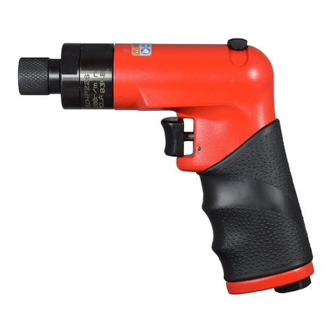
Trelawny LPS55 User manual

LPS55 Scabbler / Tamper
Operation and Maintenance Manual
www.trelawnyspt.co.uk


OPERATION
Foreword
Thank you for purchasing the LPS 55.
This manual contains the necessary
maintenance information for you to ensure
proper operation and care for your machine.
It is essential for you to read through these
manuals thoroughly.
In the unlikely event that you experience
problems with your LPS 55, please do not
hesitate to contact your local dealer or agent.
We always welcome feedback and comments
from our valued customers.
General Information
Before operating the LPS 55 Scabbler/
Tamper, this manual must be read and
understood by the operator, if in any doubt
ask your supervisor before using this
equipment. Failure to follow these instructions
could result in damage to the LPS 55
Scabbler / Tamper and/or personal injury.
Trelawny SPT Ltd disclaims all responsibility
for damage to persons or objects arising as a
consequence of incorrect handling of the tool,
failure to inspect the tool prior to starting work
for damage, or other faults that may influence
the operation or safe working of the tool, or
failure to follow the safety regulations listed or
applicable to the job site.
The tool is primarily designed for concrete
reduction and for the removal of laitance from
concrete.
The LPS 55 is also available as a Tamper and
can subsequently be fitted with a Tamper
head for the compaction of soil, tarmac or
aggregate.
This tool must not be used in a fixture.
A VL LRS 55 is also available as a vibration
reduced Compactor or Scabbler version.
All versions can be used both indoors and out.
Safety
Always, read through these instructions first
before use.
We advise you to carry out a risk assessment
and to implement measures such as; limiting
exposure time [i.e. actual trigger time, not total
time at work], job rotation, ensuring the tools
are used correctly, ensuring the tools are
maintained according to our
recommendations, and ensuring that the
operators wear personal protective equipment
[PPE] particularly gloves and clothing to keep
them warm and dry. Employers should
consider setting up a programme of health
surveillance to establish a benchmark for
each operator and to detect any early
symptoms of vibration injury.
We are not aware of any PPE that provides
protection against vibration injury by
attenuating vibration emissions.
See ‘Specifications’ section for vibration
emission data.
Further advice is available from our Technical
Department.
Starting Work
Prior to operating the tool check: -
That all fittings are secure, free from air leaks
and that air hoses are in good condition.
That all parts of the tool are fully screwed
together and secure, if you are in any doubt
ask your supervisor before using this
equipment.
That the air pressure is correct for this tool
6.2 bar (90 psi.).
That a liberal amount of lubricant has been
put into the air inlet of the tool. (See
recommended lubricants)
Before operating the tool ensure that the tool
is not near your chin or face.
Safe use of this tool requires a solid stance
and secure foothold; the operator must adopt
a firm and stable position at all times.
On start up, the tool will rise two to three
inches (75mm).
To operate the tool pull the lever towards the
handle grip.
Let the tool do the work; allow a period of time
to become accustomed to the tool. The tool
does not require any down force to operate;
excessive pressure will prevent the tool from
working effectively. Maintain contact with the
work surface with sufficient pressure only to
keep the tool under control.
Bush Hammer style headed pistons are best
suited to concrete reduction and for laitance
removal; these may reduce the likelihood of
damage to the aggregate, ensuring that a
stronger bond is created with the next layer.
Cruciform headed pistons are suited to the
reduction of concrete or where a smoother
finish is required; these will reduce the
aggregate as well as the concrete surface.
To switch off, simply release the throttle
lever.
Do not press down on the tool, excessive
pressure will prevent the tool from working to
its full capacity and will increase the vibration
emissions.
IMPORTANT
Before operating this equipment, the
operator should read this manual.
Whenever possible, he/she should be
trained how to operate the machine by an
experienced person.
Trial and error is not the safe way to
become familiar with this piece of
equipment.
Always observe safe working practices
and local safety regulations at all times.
Do not allow the tool to run unattended.
Do not allow the tool to run continuously
whilst not in contact with the surface being
prepared.
Do not modify this tool in any way, as
this will invalidate the warranty and could
lead to serious injury.
Do not use this tool in potentially
explosive environments.
Do not drag this tool by the air hose.
Do not use petrol (gasoline), thinners or
any other high flash point solvent to clean
the tool.
Air Supply
The compressed air supply must be free
from water and dirt. The installation of a
filter/regulator/lubricator air preparation set
(with moisture trap) adjacent to the tool is
strongly recommended.
Always clear the air hose before connection
to the tool. Ensure that no moisture
(condensation) is present in the air hose.
Ensure that a minimum 19mm (3/4”) bore
air hose is used and that all couplings are
secure; leak free and in good condition.
Limit the length of air hose to 15M (50ft).
Where extra length is necessary, for each
additional 15M (50ft) of air hose used, the
pressure drop is approximately 0.16bar
(3psi).
Correct operating pressure is 6.2bar (90
psi).
Do not let the operating pressure fall below
5.5bar (80p.s.i.) or rise above 6.9bar (100
psi) absolute maximum.
Preferably, the compressor should be able
to supply a minimum of 18.9 L/s (40cfm)
free air.
In particularly cold weather it is
recommended that a proprietary anti-freeze
lubricating oil be used.
Recommended Lubricants
Oil the tool daily before use. Put a liberal
quantity of one of the following zinc free air
tool lubricants through the air inlet. It is
recommended that an inline lubricator be
installed in the air hose adjacent to the tool.
SHELL Naturelle HF
CASTROL Carelube HTG 22
Cleaning
At intervals of no more than 100 hours use,
or if operation becomes unproductive, or if
the piston shows signs of sticking,
dismantle and clean with highly refined
paraffin. Replace any worn components as
necessary.
Immediately after cleaning, thoroughly oil
the tool with one of the recommended
lubricants.
Risk of Hand-Arm
Vibration Injury
These tools may cause Hand-arm Vibration
Syndrome injury if their use is not
managed.
Do wear Personal Protective Equipment
including safety goggles, footwear, ear
defenders and gloves.
In some environments it will be necessary to
wear facemasks or breathing apparatus.
Do be aware that this tool is not
electrically insulated.
Do ensure that this tool is lubricated daily.
Do be aware that this tool can create dust
and flying debris.
Do be aware of others working around
you.
Do keep hands and clothing away from
moving parts.
Do store this tool in a secure and dry
environment.

OPERATION / MAINTENANCE
Handled correctly the LPS 55 Scabbler/
Tamper will work quickly and efficiently.
Gloves and personal protective equipment
must be worn when using this tool.
Care must be taken to avoid damaging or
tripping over the air hose.
Maintenance
Only a competent person, in a suitably
equipped workshop, must carry out
maintenance. Disconnect the tool from the
air supply before carrying out any of the
following operations.
Dismantling
Clean all debris from the exterior of the tool.
Handle/Valve Body servicing
Hold main shaft in a vice, about three
inches (75mm) away from the cylinder
assembly, slacken off the locknut (10)
using a 38mm (1½) wrench on the spanner
flats. Retain the sealing washer (10a). Then
unscrew the valve body assembly from the
main shaft.
Secure the valve body assembly (14) in a
vice, holding on the main body casing.
Using a suitable spanner unscrew the
adapter (19) from the valve body, remove
the spring (21) and spring seat (20),
retrieve the valve stem (24) with its
O’Rings. Using a 6mm punch, drive out the
throttle lever pivot pin (25) and withdraw the
throttle lever (12).
Piston and Cylinder removal
(Threaded Piston)
Hold the Scabbler head (7) or Tamper foot
securely in a vice, then using a 1¼” (32mm)
spanner on the piston flats, unscrew the
Scabbler head or Tamper foot. Using a
suitable wrench on the spanner flats on the
cylinder remove the cylinder and then the
piston (6) from the cylinder (2). Remove the
piston O' Ring (not shown in the exploded
diagram) and remove cylinder wiper seal
(5) and O' Rings (3) and (4).
(Pin fit Piston)
Hold the Scabbler head (7) or Tamper foot
securely in a vice, then using a 12mm
punch drive out the retaining spiral pin (8)
and remove the Scabbler head or Tamper
foot. Using a suitable wrench on the
spanner flats on the cylinder remove the
cylinder and then the piston (6) from the
cylinder (2). Remove cylinder wiper seal (5)
and O' Rings (3) and (4).
Assembly
Before any assembly takes place, ensure
all parts are clean and have a film of air tool
oil lubrication unless otherwise stated.
Avoid lubricating oil contaminating the
threads of the cylinder (2), the main shaft
(9) and the valve body (14). These will
require securing with a thread-locking
adhesive. It is good practice to renew all the
O'Rings. Replace any parts showing signs
of wear; paying particular attention to the
small bore of the cylinder.
Handle/Valve Body Assembly
Apply general-purpose bearing grease to
the valve stem, insert valve stem (24) with
its O'Rings (22) and (23) into valve guide
followed by the spring (21). Screw in
adaptor (19) by hand and using a
32mm (1¼) spanner fully tighten. Using a
6mm punch align the hole in the throttle
lever (12) with the holes in the valve body
(14). Using a small hammer fit the throttle
lever pin (25).
Piston and Cylinder Assembly.
(Threaded Piston)
Fit a new wiper seal (5) and O' rings (3)
and (4) to the appropriate small and large
grooves on the cylinder (2). Fit a new
O' ring on to the piston (6) and insert into
the cylinder. Screw on the Scabbler head
(7) or Tamper foot until it butts up against
shoulder of piston. Hold in a vice, gripping
on the Scabbler head or Tamper foot using
the spanner flats. Fully secure using a
suitable wrench on the piston’s spanner
flats to a torque of 500lbs/ft (678Nm).
Ensure that the threads of the cylinder and
casing assembly are clean and free of oil;
apply a bead of Loctite 243 or similar to the
first few threads of the cylinder. Hold the
casing assembly in a vice using the flats
provided and screw in the cylinder
assembly by hand, using a suitable wrench
on the spanner flats on the cylinder tighten
to a recommended torque of
135Nm (100 lbs/ft).
Piston and Cylinder Assembly.
(Pin fit Piston)
Fit a new wiper seal (5) and both O' rings
(3) and (4) to the appropriate small and
large grooves on the cylinder (2). Insert the
piston (6) into the cylinder. Fit the Scabbler
head (7) or Tamper foot until it butts up
against the front face of the piston (6). Align
the holes in the piston and Scabbler head
or Tamper foot. A ” Allen Key is a good
fit for this purpose or use a suitable piece of
wooden dowelling. Hold the spiral pin (8)
with a pair of pliers to avoid hitting the
fingers, and then using a hammer, drive in
the spiral pin centrally to secure the
Scabbler head or Tamper foot.
Ensure that the threads of the cylinder and
casing are clean and free of oil; apply a bead
of Loctite 243 or similar to the first few threads
of the cylinder. Hold the casing assembly in a
vice on the flats provided and screw in the
cylinder assembly by hand. Using a suitable
wrench on the spanner flats on the cylinder
tighten to a recommended torque of 135Nm
(100 lbs/ft).
Body Assembly
Hold main shaft in a vice, about three inches
(75mm) away from the valve assembly.
Ensure sealing washer (10a) is in place and
that the threads of the valve body (14) and
main shaft (9) are clean and free of oil; apply
a bead of Loctite 243 or a similar product to
the first few threads of the Handle and screw
on the valve body until hand tight.
Tighten the locknut (10) using a 38mm (1 ”)
wrench on the spanner flats.
Machine Storage
Storage: over 3 months.
Clean the outside of the machine and inspect
the piston and cutterhead for wear, replace
any worn parts as required. Put a liberal
amount of lubricant into the air inlet of the tool
and run the tool for a few seconds to disperse
the oil around the tools internal components.
Lubricate the exposed part of the piston and
cylinder. (See recommended lubricants)
Cover the machine to protect it:
Store the machine in a dry place.
When next used, continue as per “Starting
work section”.
Disposal
When the tool and its accessories are taken
out of service for disposal, it is recommended
that: - It is dismantled into component form,
segregated according to material composition
and disposed of using waste recycling
processes specified by local regulations.
Machinery Directive
Information
This tool has been designed and produced in
accordance with the following directives:
2006/42/EC Machinery Directive
and applicable harmonised standard:
EN ISO 1 1148-4:2012
If your company has any problem with our
products or would like to discuss the possibility
of an improvement being made to them, then
please do not hesitate to contact us. Your
comments are both important and appreciated.
SCABBLER/TAMPER
Length 1300mm (51)”
Weight 13.45kg (29.6lbs)
Blows per minute 1300
Air Pressure 6.2 bar (90psi) - (1/2” BSP Air inlet)
Air Consumption 11.61 lps (25cfm)
Sound pressure level 98.0db(A)
Vibration Level (H1)* 38.6m/s2 (k= 2.92m/s²)**
Vibration Level (H2)* 37.5m/s2 (k= 21.36m/s²)**
H1* Indicates test taken from the primary handgrip location at the trigger.
H2* Indicates test taken from the secondary handgrip location.
(K)** Equals the factor of uncertainty, which allows for variations in measurement and production.
Vibration data figures are tri-axial, which gives total vibration emission.
Risk of Hand Arm Injury
Because of various factors, the range of vibration emission during intended use can vary.
The vibration is dependent on the task, the operators grip, and feed force employed etc.
Noise level measured in accordance with: EN ISO 15744: 2008
Vibration measured in accordance with: EN ISO 28927:2012 and EN ISO 20643:2005

EXPLODED VIEW
EXPLODED VIEW

PART NUMBERS
All rights reserved. Any unauthorised use or copying of the contents or part thereof is prohibited.
This applies to trademarks, model denominations, part numbers and drawings.
Use only genuine Trelawny spares.
The use of non-Trelawny spare parts invalidates the warranty.
TROUBLE SHOOTING
Low air pressure. Ensure that the air pressure is correct at 90psi, max 100psi.Poor performance or lack of
power If tool has been left for some time without use, the
oil may dry out slightly causing a sticky residue.
Strip tool down and re-oil.
Tool worn out, can you feel excessive side ways
movement between the piston and cylinder bore.
Replace the piston and cylinder, along with a new scraper seal.
Cutterhead worn out. Replace cutterhead
Applying to much down force. Only apply sufficient down force to stop the tool from bouncing.
Tool continues to run with
trigger released
Valve seal may have become dislodged through the
tool being disconnected with the trigger in the open
position.
Ensure that the trigger has not been taped or wired in the open
position.
Do not use quick release couplings to switch tool off.
Cutterhead seized on piston If the tool has been laid up or used with water
present, rust may have built up between the piston
and cutter.
In extreme cases it may be necessary to apply heat to release
the cutter head, otherwise a releasing agent may be sufficient.
Item
No
Part No Description Item
No
Part No Description
1411.5011 Body 17 843.0765 3/4” Claw coupling
2613.5001 Cylinder 18 819.5020 90° Adapter
3809.6599 Cylinder O’Ring (Small) 19 627.5011 Adaptor (Spring seat)
4809.6619 Cylinder O’Ring (Large) 20 627.5012 Spring Seat
5829.5001 Wiper Seal 21 712.5001 Valve Spring
6612.5005 Piston (Pin Fit) 22 809.5599 Valve Stem Seat O’Ring
612.5001 Piston (Screw Fit) 23 809.0069 Valve Stem Seal O’Ring
7441.5359 TCT tip 5 point Scabbler Head (Pin fit) - inc pin 24 618.5025 Valve Stem
441.5360 TCT tip Cruciform Scabbler Head (Pin fit) i- nc pin 448.5025 Valve Stem - including O’Rings
441.5369 TCT tip 9 point Scabbler Head (Pin fit) - inc pin 25 813.0636 Roll Pin
426.5051 TCT tip 5 point Scabbler Head (Screw fit)
426.5052 TCT tip Cruciform Scabbler Head (Screw fit) Not shown in exploded view
809.6499 Piston O’Ring (Screw fit)
8813.1050 Spirol Pin (Pin fit heads) 450.5001 100 x 100 Compactor Foot (Screw fit)
450.5011 100 x 100 Compactor Foot (Pin fit)
9624.5011 Main Shaft 450.5003 127 x 152mm Compactor Foot (Screw fit)
10 625.5012 Locknut (Main shaft) 450.5013 127 x 152mm Compactor Foot (Pin fit)
10a 810.9003 Sealing Washer 450.5006 100 x 200mm Compactor Foot (Screw foot)
11 665.5011 Trigger Guard 450.5016 100 x 200mm Compactor Foot (Pin foot)
12 649.5011 Throttle Lever 450.5007 127 Diameter Compactor Foot (Screw fit)
13 822.2000 Rubber Grip 450.5017 127 Diameter Compactor Foot (Pin fit)
14 422.5005 Valve Body 852.0812 Trigger Guard Screw
15 634.5015 Blanking Cap
16 625.5011 Locknut (Valve body handle)

Trelawny SPT Ltd
13 Highdown Road, Sydenham Industrial Estate, Leamington Spa,
Warwickshire, CV31 1XT, United Kingdom
Telephone: +44 (0)1926 883781 - Fax: +44 (0)1926 450352
Email: sales@trelawny.co.uk
© TSPT UK 2009 Part No: 735.5005 issue 4.11.16 www.trelawnyspt.co.uk
Table of contents
Other Trelawny Tools manuals
Trelawny
Trelawny VLSF1EX User manual
Trelawny
Trelawny VL203Ex Troubleshooting guide
Trelawny
Trelawny Trident Neptune User manual

Trelawny
Trelawny Vibro Lo Troubleshooting guide
Trelawny
Trelawny VL223EX Series User manual
Trelawny
Trelawny SF3EX User manual
Trelawny
Trelawny SF11EX User manual

Trelawny
Trelawny Single Scaler Standard Duty User manual
Popular Tools manuals by other brands
FUCHS LUBRITECH
FUCHS LUBRITECH Single-handed How to use
Framers Corner
Framers Corner M3 Operator's manual

Milwaukee
Milwaukee M12 2435-20 Operator's manual
HAZET-WERK
HAZET-WERK 772-2/16 operating instructions
Johnson
Johnson LEVEL UP 1920-0800D Operator's manual

Berner
Berner GEDORE 1.06 operating instructions
