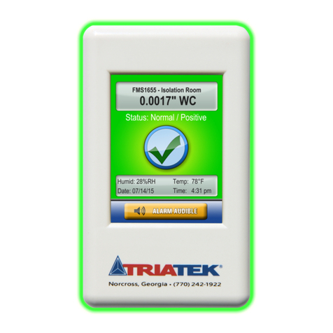
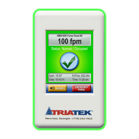
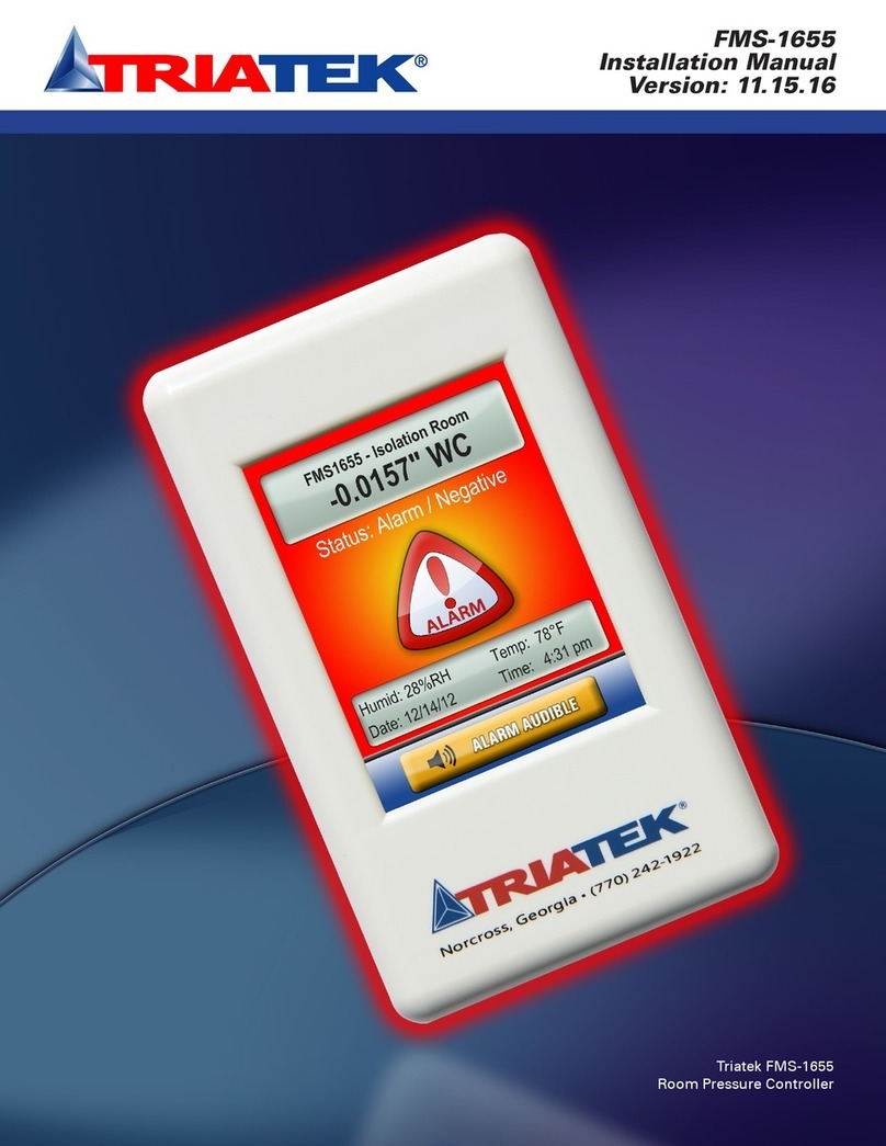
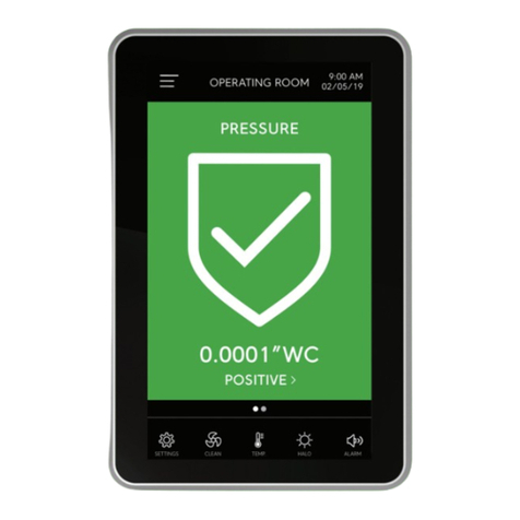
TRIATEK FMS-1650 Manual

FMS-1650
Programmer’s Guide
Version: 5.16.13
TRIATEK FMS-1650
The Next Generation in Critical Airflow Controls

FMS-1650
Due to continuous improvement, TRIATEK reserves the right to change product specifications without notice.
GENERAL ……………………………………………………………………………………………………………………………………………… 1 - 2
Specifications …………………………………………………………………………………………………………………………………… 1 - 2
Part Number Guide …………………………………………………………………………………………………………………………………… 2
OVERVIEW ………………………………………………………………………………………………………………………………………………… 4
MAIN SETUP MENU …………………………………………………………………………………………………………………………… 5 - 19
Introduction …………………………………………………………………………………………………………………………………… 5 - 14
Configuring Controller Settings ………………………………………………………………………………………………………………… 6
Setting up the Main Sensor Input …………………………………………………………………………………………………… 7 - 8
Setting up the Damper Control Output …………………………………………………………………………………………… 8 - 9
Setting up the Door Switch …………………………………………………………………………………………………………… 10
Setting up the Alarm Relay ……………………………………………………………………………………………………… 10 - 11
Adjusting the PID Loop Settings ………………………………………………………………………………………………… 11 - 12
Configuring the Alarm Parameters …………………………………………………………………………………………………… 12
Setting up the Alarm Buzzer ……………………………………………………………………………………………………… 12 - 13
Selecting Engineering Units ………………………………………………………………………………………………………… 14
Configuration Isolation Room Settings ………………………………………………………………………………………………… 15 - 16
Selecting the Mode(s) of Isolation …………………………………………………………………………………………………… 15
Setting the State(s) of Occupancy …………………………………………………………………………………………………… 16
Modifying the Room Name(s) ………………………………………………………………………………………………………… 16
Configuring Network Settings …………………………………………………………………………………………………………… 17 - 19
Setting up BACnet Parameters ………………………………………………………………………………………………… 17 - 18
Choosing the Baud Rate ………………………………………………………………………………………………………… 18 - 19
Setting the Network or MAC Address ………………………………………………………………………………………………… 19
SYSTEM SETUP ………………………………………………………………………………………………………………………………… 20 - 39
Configuring Secondary Analog Inputs ………………………………………………………………………………………………… 20 - 26
Setting up Analog Inputs for Pressure…………………………………………………………………………………………… 21 - 22
Setting up Analog Inputs for Flow ……………………………………………………………………………………………… 22 - 23
Setting up Analog Inputs for Humidty ……………………………………………………………………………………………23 - 24
Setting up Analog Inputs for Temperature Setpoint Adjust …………………………………………………………………… 24 - 25
Setting up Thermistor Inputs …………………………………………………………………………………………………… 25 - 26
Configuring Secondary Analog Outputs ……………………………………………………………………………………………………… 27
Remapping the Secondary Analog Outputs ………………………………………………………………………………………………… 28
Configuring Secondary Digital Inputs ………………………………………………………………………………………………………… 29
Configuring Secondary Relay Outputs ……………………………………………………………………………………………………… 30
Configuring Secondary PID Loops …………………………………………………………………………………………………………… 32
Configuring Universal Alarm Settings …………………………………………………………………………………………………… 33 - 36
Enabling Individual Visual Alarms ……………………………………………………………………………………………… 33 - 35
Enabling Individual Audible Alarms ……………………………………………………………………………………………… 35 - 36
Configuring Engineering Units for Secondary Inputs ……………………………………………………………………………………… 37
Managing System Passwords ……………………………………………………………………………………………………………… 38 -39
Adding a New Password ……………………………………………………………………………………………………………… 38
Editing an Existing Password …………………………………………………………………………………………………… 38 - 39
Deleting an Existing Password
………………………………………………………………………………………………………… 39
Purging All Passwords ………………………………………………………………………………………………………………… 39
DISPLAY SETUP ………………………………………………………………………………………………………………………………… 40 - 49
Selecting the Display Options …………………………………………………………………………………………………………… 40 - 43
Using Single Sensor Mode ……………………………………………………………………………………………………… 40 - 41
Using Dual Sensor Mode ………………………………………………………………………………………………………… 41 - 42
PROGRAMMER’S GUIDE
Table of Contents
TRIATEK reserves the right to change product specifications without notice.

FMS-1650
Due to continuous improvement, TRIATEK reserves the right to change product specifications without notice.
PROGAMMER’S GUIDE
Table of Contents
Using the Triple Sensor Mode ………………………………………………………………………………………………………… 42
Using the Quad Sensor Mode ………………………………………………………………………………………………………… 42
Customizing the FMS-1650 Display …………………………………………………………………………………………………… 43
Selecting the Display Options ……………………………………………………………………………………………………………… 44 - 45
Modifying Input Names ………………………………………………………………………………………………………………………… 46
Setting System Time & Date …………………………………………………………………………………………………………………… 47
Selecting an Alternate Language ……………………………………………………………………………………………………………… 48
Additional Display Options ……………………………………………………………………………………………………………………… 49
Enabling the Screensaver Option ……………………………………………………………………………………………………………… 49
DIAGNOSTICS …………………………………………………………………………………………………………………………………… 50 - 57
Getting System Information ……………………………………………………………………………………………………………………… 50
Using Override Capabilities ……………………………………………………………………………………………………………………… 52
Zero Calibrating the FMS-1650 …………………………………………………………………………………………………………… 53 - 54
Using the Real-Time View Option ………………………………………………………………………………………………………… 55 - 56
Testing/Resetting/Restoring the FMS-1650 …………………………………………………………………………………………………… 57
TYPICAL APPLICATIONS FOR THE FMS-1650
……………………………………………………………………………… 59 - 63
Wiring & Configuring External Devices ………………………………………………………………………………………………… 59 - 63
Wiring ……………………………………………………………………………………………………………………………………… 59
Configuring Hardware Resources ……………………………………………………………………………………………………… 59
Confirm Internal Pressure Sensor Settings ……………………………………………………………………………………… 59 - 60
Configure Remote Pressure Sensor ………………………………………………………………………………………………… 60
Configure Humidity Sensor …………………………………………………………………………………………………………… 60
Configure Flow Sensor ………………………………………………………………………………………………………………… 60
Configure Temperature Sensor …………………………………………………………………………………………………… 60 - 61
Configuring Analog Outputs …………………………………………………………………………………………………………… 61
Configure Primary Exhaust Damper Control ………………………………………………………………………………………… 61
Configure Secondary Exhaust Damper Control ……………………………………………………………………………………… 61
Configuring Door Switch Input …………………………………………………………………………………………………… 61 - 62
Configuring Alarm Relay ………………………………………………………………………………………………………………… 62
Complete Room Controller Example ………………………………………………………………………………………………… 63
PID TUTORIAL …………………………………………………………………………………………………………………………………… 64 - 65
Control Loop Basics ……………………………………………………………………………………………………………………………… 64
PID Controller Theory …………………………………………………………………………………………………………………………… 64
Proportional Term …………………………………………………………………………………………………………………………… 64 - 65
Integral Term ……………………………………………………………………………………………………………………………………… 65
Derivative Term …………………………………………………………………………………………………………………………………… 65
MODULE SETTINGS
…………………………………………………………………………………………………………………………… 66 - 71
Configure main Controller Settings …………………………………………………………………………………………………………… 66
Configurations & Settings ………………………………………………………………………………………………………………………… 67
BACnet Objects ……………………………………………………………………………………………………………………………… 68 - 69
Metasys N2 Ojects …………………………………………………………………………………………………………………………… 70 - 71
FLOW DIAGRAMS ……………………………………………………………………………………………………………………………… 72 - 77
Unit Setup Tree …………………………………………………………………………………………………………………………………… 72
System Setup Tree …………………………………………………………………………………………………………………………… 73 - 75
Display Setup Tree ………………………………………………………………………………………………………………………………… 76
Diagnostics Tree …………………………………………………………………………………………………………………………………… 77
TRIATEK reserves the right to change product specifications without notice.

- 1 -
FMS-1650
Due to continuous improvement, TRIATEK reserves the right to change product specifications without notice.
Electrical
Optional External Remote Sensor Distance ……………………………………………………………………………………………………up to 4,000 feet
Optional External Remote Sensor ………………………………………………………………………………Wiring 18-22 AWG, shielded twisted pair
Power Supply …………………………………………………………………………………………………………………………………24 Vac ±10%, 30Va
Accuracy of Measurement ……………………………………………………………………………………………………………………………±0.5%FS
Pressure Range ……………………………………………………………………………………………………………………………………±0.2500 “WC
*NIST Traceable / Individual certification available as option
Pressure/Flow ……………………………………………………………………………………………………………………………………up to 0.25 ”WC
4 Analog Inputs …………………………………………………………………………………………………………………4-20mAdc, 0-5Vdc or 0-10Vdc
4 Analog Outputs ………………………………………………………………………………………………………………4-20mAdc, 0-5Vdc or 0-10Vdc
2 Thermistor Inputs …………………………………………………………………………………………………………NTC Type 2 or 3, 10kΩ@ 25°C
4 Digital Inputs ………………………………………………………………………………………………0-5Vdc or 0-24Vdc, Active-High or Active-Low
4 Relay Outputs ………………………………………………………………………………………………………………………………………1A@24Vdc
Control Signal Wire Size ……………………………………………………………………………………………………………………18 AWG minimum
Power Supply ……………………………………………Class 2, 24Vac ±10%, 30VA 110 to 24Vac, 60 Hz, step-down isolation transformer provided
Communications
BACnet® MS/TP network …………………………………………………………………………………………Two-Wire Twisted Pair, RS-485 signaling
Metasys® N2 network ………………………………………………………………………………………………Two-Wire Twisted Pair, RS-485 signaling
LonWorks® FTT-10A peer-to-peer network ………………………………………………………………………Two-Wire Twisted Pair, FTT-10A signaling
Recommended Cable Type ……………………………………………………………………………………………………………………… Belden 1325A
GENERAL
Specifications
TRIATEK reserves the right to change product specifications without notice.

- 2-
FMS-1650
GENERAL
Specifications
Touch Screen User Interface
LCD Size ……………………………………………………………………………………………………………………………………………3.2” diagonal
LCD Type ……………………………………………………………………………………………………………………………………………Transmissive
Resolution ………………………………………………………………………………………………………………………………………240 x 320 portrait
Viewing Area ……………………………………………………………………………………………………………………………50.60 mm x 66.80 mm
Color Depth …………………………………………………………………………………………………………………………………18-bit or 262K colors
Backlight Color ………………………………………………………………………………………………………………………………………………White
Luminous Intensity ………………………………………………………………………………………………………………………………min 2500 cd/m2
Mechanical
FMS-1650 Internal Sensor Flush Mount Housing (Brushed Stainless Steel) Housing ……………………………………………5.6”W x 8.5”H x 1.9”D
FMS-1650 Display Module Housing ………………………………………………………………………………………………………3”W x 5”H x 0.75”D
Optional External Remote Sensor Housing …………………………………………………………………………………………………2”W x 3”H x 2.7”D
Stainless Steel Cover Plate for Flow Tube ……………………………………………………………………………………………2.7”W x 4.5”H x 0.2”D
Stainless Steel Cover Plate for Remote Sensor ………………………………………………………………………………………2.7”W x 4.5”H x 0.2”D
FMS-1650 w/ Flow Tube Cover Plate ……………………………………………………………………………………………………………approx. 3.5 lb
FMS-1650 w/ Optional External Remote Sensor ………………………………………………………………………………………………approx. 4.0 lb
FMS-1650 Mounting Options ……………………………………………………………………………………………………………………Surface, Flush
Flow Tube Cover Plate Mounting ……………………………………………………………………………………………………………………………Flush
Optional External Remote Pressure Sensor Mounting ……………………………………………………………………………………………………Flush
Environmental
Operating Temperature …………………………………………………………………………………………………………………32° to 125° F Operating
Operating Humidity ……………………………………………………………………………………………………………10% - 95% RH, Non-condensing
TRIATEK reserves the right to change product specifications without notice.
Part Number Guide FMS1650 ---
Case Style Internal Sensor 1# Remote Sensors # Optional Sensors 2
S = surface 0 = no internal sensor 0 = no remote sensors (demo) Blank = no optional sensors
F = flush 1 = standard internal sensor 1 = one standard remote sensor 1 = one optional remote sensor
T = thin R = optional remote display 32 = two standard remote sensors 2 = two optional remote sensors
3 = three standard remote sensors 3= three optional remote sensors
4 = four standard remote sensors 4 = four optional remote sensors
A = optional no-flow internal sensor L = legacy standard remote sensor(s)
B = custom remote sensor
N = no remote sensors
1Internal sensor option only available on flush-mount model FMS1650-F-x-x
2This digit only applies to optional sensors specified in preceding digit or when ordering legacy 2-wire remote sensors
3Optional remote display does not include internal sensor

PROGRAMMER’S GUIDE
FMS-1650
TRIATEK reserves the right to change product specifications without notice.
- 3-
CAUTION
FAST ACTING
ELECTRONIC ACTUATOR
Controller Actuator
120/24VAC, 30Va Transformer
Supplied by Triatek
120/24VAC, 20Va Third Party
Transformer
CORRECT
Failure to follow the wiring diagrams could result in damage to
your equipment and could void your warranty. Wiring diagrams
can also be found at www.triatek.com.
Under no circumstances should a single transformer be split
between actuator and controller. Doing so will damage the
actuator, the transformer, the controller or all units. A single
120/24V 30Va transformer is required for the controller and a
separate 120/24V 20Va transformer is required for the actuator.
CORRECT

OVERVIEW
FMS-1650 Overview
FMS-1650
TRIATEK reserves the right to change product specifications without notice.
- 4 -
The touch-screen user interface of the FMS-1650 room pressure
controller is designed to facilitate the initial setup and configuration,
diagnosis, and troubleshooting during the installation process. Each
menu screen is limited to four options, thereby simplifying navigation
through the menu system. Context-sensitive help (Figure 2) is
available at most menu screens and is accessed simply by touching
the menu title on that screen. To exit from any help screen, simply
touch the display anywhere on the popup. Multi-page menu screens
have navigation buttons at the bottom of each screen that allow the
user to move forward or backward, and include a convenient exit
button on the last screen (Figure 1) to quickly exit the menu system to
return to the main display.
To preserve the security of the configuration settings, up to ten (10)
multilevel passwords may be programmed to prevent unauthorized
access to the system configuration settings. To further prevent
unauthorized access, the FMS-1650 user menu system incorporates
display timeout periods based on the screen currently displayed. Menu
screens timeout after 90 seconds of inactivity, while popup screens
automatically timeout after 60 seconds. This prevents unauthorized
access to the menus should a unit be inadvertently left unattended at
one of the user menus or configuration screens.
Figure 2. Context-
sensitive help is
available at most menu
screens simply by
touching the menu title
at any screen.
Figure 1. Navigation
buttons appear at each
menu screen which
facilitates moving
through the user menu
system.

MAIN SETUP MENU
Introduction
FMS-1650
TRIATEK reserves the right to change product specifications without notice.
- 5-
The Main Setup menu provides four options for 1) configuring
the settings specific to the unit as a room pressure controller, 2)
configuring the settings associated with the additional hardware
resources, as well as managing the system security passwords, 3)
configuring the display-specific settings, and 4) using the diagnostics
and troubleshooting resources (Figure 3).
If this FMS-1650 is being used primarily as a room pressure controller
monitoring a single room, then the majority of the configuration settings
will be available through the Unit Setup option on the Main Setup
Menu. The options for configuring the additional hardware resources
available on the FMS-1650 may be accessed through the System
Setup options. These additional hardware resources include universal
analog inputs 2 through 4, dedicated thermistor inputs 1 and 2, analog
outputs 2 through 4, digital inputs 2 through 4, and relay outputs 2
through 4. Other additional resources available through the System
Setup options include the secondary PID control loops associated with
analog outputs 2 through 4, the comprehensive alarm facility, and the
security password management facility.
The Display Setup option has six options available for configuring all
of the display-specific settings integrated in the FMS-1650. These
options include setting the primary display mode, selecting the
individual display options, defining the names associated with each
analog input, setting the system time and date, selecting the language
for the user interface, and adjusting the brightness of the touch screen
display. The FMS-1650 can simultaneously display the differential
pressure, ambient temperature, relative humidity, and air change rate
for the monitored room in real-time. The sources for each of these
displayed parameters may easily be specified using Display Options
on the Display Setup menus.
The Diagnostics options provide information specific to this particular
FMS-1650 unit, assistance with the troubleshooting of the unit, and
real-time confirmation of the signals connected to the backplane.
The Overrides option on the Diagnostics menus allows the analog
outputs and relay outputs to be manually overridden independently
to assist with verifying the correct operation and/or allocation of the
controller resources. There are two options that provide support for
zero-calibrating the FMS-1650 once it has been installed, to ensure
maximum accuracy of the displayed differential pressure readings. To
further assist with troubleshooting the FMS-1650 during the installation
phase, the Real-Time View option on the Diagnostics menus allows the
user to view the real-time conditions of each of the resources attached
to the FMS-1650 controller.
More information on each of the four options on the Main Setup Menu
is available in subsequent sections of this guide. The next section
covers the options available on the Unit Setup menu.
Figure 3. Main Setup
menu provides access
to configuration of all
FMS-1650 settings.

UNIT SETUP
Configuring Controller Settings
FMS-1650
TRIATEK reserves the right to change product specifications without notice.
- 6 -
(For overview, see FLOW DIAGRAMS - Page 72)
Configuring Controller Settings
The Unit Setup menu shown in Figure 4 provides support for:
1. Configuring the controller settings
2. Configuring the settings associated with the room being monitored
and/or controlled
3. Configuring the network-specific settings of the controller module
4. Using options for sharing configuration data between this
controller and another controller on the same network
The Controller Setup options provide access to facilities for configuring
all of the settings associated with the FMS-1650 when primarily being
used as a room pressure controller. This includes setting up the
analog input and output, door switch, alarm relay, PID control loop,
alarm setpoints, audible alert settings, and the engineering units for
the differential pressure reading. If the FMS-1650 is being used with
multiple differential pressure sensors, the Controller Setup options
allow the primary sensor to be configured, while the System Setup
options must be used to configure the secondary sensor(s).
If the FMS-1650 is being used primarily as a room pressure controller,
the Room Setup option provides access to the settings associated with
the spaces being monitored and/or controlled. Options available on
the Isolation Room Setup menu include selecting the mode of isolation,
the state of occupancy of the monitored space, and defining the name
associated with each space or room being monitored and/or controlled.
The Network Setup option provides support for configuring the settings
associated with the networking capability of the FMS-1650. These
options include selecting the baud rate for the network interface (if
the current protocol is BACnet MS/TP), setting the network or MAC
address for the unit, and setting several parameters specific to the
BACnet® protocol such as the device ID offset and the Max_Master
parameter. The available options on the Network Setup menu strictly
depend on the protocol selected at the controller module via hardware
configuration switch settings. More information on the two different
sets of menu options is given in the Configuring Network Settings
section later in this document.
To share configuration data with other controllers on the same
RS-485 network, the Share Configuration option provides support for
accomplishing this task. These options include specifying the address
to which configuration data should be sent, putting the unit into receive
mode waiting for configuration data from another unit on the same
network, and displaying the configuration data associated with this
specific unit. Currently, these options have been reserved for factory-
use only, but are expected to be made available to end users in a
future release of the FMS-1650 firmware. Consult the factory for more
information on this feature.
The next section details the options available on the Controller Setup
menus.
Figure 4. Unit Setup
menu provides options
for configuring the
controller settings,
room settings, network
settings, and sharing
configuration data.

UNIT SETUP
Configuring Controller Settings
FMS-1650
TRIATEK reserves the right to change product specifications without notice.
- 7 -
The Controller Setup menus shown below in Figure 5 and Figure 6
provide access to facilities for configuring all of the settings associated
with the FMS-1650 when it has been set up as a room pressure
controller, including setting up the analog input and output, configuring
the door switch input, setting up the alarm relay, configuring the PID
loop settings, alarm setpoints, audible alert settings, and selecting the
engineering units for the differential pressure reading.
Setting up the Main Sensor Input
The Analog Input option on the Controller Setup menus allows
the primary differential pressure sensor input to be configured as
required by the specific application. Selecting this option invokes
the Sensor Input Settings configuration screen shown in Figure 8. At
this configuration screen, the user may specify whether or not the
linearization of the sensor input should be enabled, and whether or
not to invert the analog input signal. The Inverted Mode option is very
useful if the actual remote sensor connected to the FMS-1650 was
installed backwards inadvertently, such that the reference and monitor
ports of the pressure sensor are reversed. Selecting the Inverted
Mode is equivalent to manually reversing the tubing at the remote
sensor ports.
Figure 7. Engineering
units and input signal
range may be selected
during configuration.
Figure 6. The
Controller Setup menu
(1 of 2) allows all of the
hardware resources
for the primary room
controller to be
configured.
Figure 5. The
Controller Setup
menu (2 of 2) allows
the capabilities of the
primary room controller
to be configured.

UNIT SETUP
Configuring Controller Settings
FMS-1650
TRIATEK reserves the right to change product specifications without notice.
- 8 -
Clicking the Next button invokes the Sensor Input Settings
configuration screen shown in Figure 7, where the engineering units
may be selected, as well as the voltage or current range for the sensor
input. For internal sensor models (FMS1650-F-1-x), the sensor input
defaults to the 0-5V range, and clicking the Next button invokes the
Enter XX-ISO Setpoint configuration screen. For remote sensor
models (FMS1650-x-0-1), the sensor input defaults to the 4-20mA
range.
Clicking the Next button invokes the AI-1 Sensor Range configuration
screen as shown in Figure 9, where the pressure range associated
with the remote sensor may be specified. The default pressure range
for all standard FMS-1650 models is ±0.25 “WC, although existing
remote sensor units may have pressure ranges that match one of the
other choices on this setup screen. Once the pressure range has been
specified, the user is prompted to enter the setpoint for the current
isolation mode.
Setting up the Damper Control Output
The Analog Output option on the Controller Setup menus allows the
primary control output to be configured as required by the specific
application. Selecting this option invokes the Analog Output Settings
configuration screen (Figure 10). Each of the four (4) analog outputs
of the FMS-1650 may be configured for one of two operating modes:
Direct Analog Output or PID Analog Output.
The direct analog output or proportional mode allows the output to
track the mapped analog input directly or inversely. The PID mode
employs the proportional-integral-derivative scheme for closed-loop
control of the analog output. Independent of the mode for which the
analog output is configured, the range of the output may or may not
include an offset.
Selecting the 0-5V,0-10V,0-20mA range allows the analog output to
swing from zero to the maximum specified by the hardware dipswitch
selection, while the 1-5V,2-10V,4-20mA range includes an offset from
zero.
Figure 9. Multiple
differential pressure
ranges are supported
by the FMS-1650.
Figure 8. Sensor
Input Settings popup
screen allows the input
signal to be inverted
if the sensor was
inadvertently installed
backwards.

UNIT SETUP
Configuring Controller Settings
FMS-1650
TRIATEK reserves the right to change product specifications without notice.
- 9-
Once the operating mode and output range have been specified, the
next Analog Output Setup configuration screen prompts the user to
specify the minimum and maximum limits for the analog output in
percentage (Figure 11). The default minimum and maximum are zero
and 100 percent, respectively. This allows the analog output to not
exceed or go below a predetermined voltage or current output.
Clicking the Next button invokes the last Analog Output Settings
configuration screen (Figure 12), where the user can specify the
analog input to which this analog output should be mapped, and
select the action mode for the analog output. The default setting uses
AI-1 as the analog input channel for the analog output. The action
mode determines the direction in which the output is driven based on
the sensor input (AI-1). The default action mode is Direct Acting for
positive isolation and Reverse Acting for negative isolation. Neutral
isolation mode defaults to Direct Acting mode for the primary analog
output.
Figure 11. Upper and
lower limits for each
analog output may be
specified, independent
of offset from zero.
Figure 12. Input
channel used by the
main analog output
may be selected
independently for each,
as well as the action
mode.
Figure 10. Proportional
(direct) and PID analog
output modes are
supported.

UNIT SETUP
Configuring Controller Settings
FMS-1650
TRIATEK reserves the right to change product specifications without notice.
- 10 -
Setting up the Door Switch
The FMS-1650 uses digital input 1 (DI-1) as the door switch input for
the primary isolation room. This capability allows the FMS-1650 to
monitor the door to the monitored room and use the status of the door
to delay the sounding of alarms and/or hold the analog output fixed
until the door returns to the closed position. The Door Switch option
on the Controller Setup menus allows the door switch input to be
configured as required by the specific application. Selecting this option
invokes the Door Switch Settings configuration screen shown below
(Figure 14).
The door switch input may be configured for one of two modes:
Normally-Open or Normally-Closed. While any suitable switch may
be used with the FMS-1650, the door switch provided by Triatek (part
no. SWD200-2) supports both normally-open (N.O.) and normally-
closed (N.C.) operating modes. After selecting N.O. or N.C. for the
door switch, set the delay as required by the specific installation. The
default value for the door delay is zero seconds, but can be as long as
180 seconds, or three minutes.
When the door to the monitored room opens, the door delay timer
begins counting down, and inhibits the alarm buzzer and alarm relay
from triggering until the timer expires. If the audible alert is configured
with a delay, the door delay counts down first, and then the audible
alert delay begins timing. Similarly, if the alarm relay has a delay
associated with it, it begins counting down after the door delay expires.
Setting up the Alarm Relay
The FMS-1650 uses relay output 1 (RL-1) as the alarm relay output
for the primary isolation room. This capability is typically used to allow
the FMS-1650 to trigger a remote alarm annunciator. The Relay Setup
option on the Controller Setup menus allows the alarm relay output to
be configured as required by the specific application. Selecting this
option invokes the Relay 1 Trigger Mode configuration screen shown in
Figure 13. The alarm relay output may be configured to be triggered
in one of three modes: Setpoints, Isolation Mode, or Occupancy Mode.
Setpoints Mode uses a pair of setpoints to determine when to activate
or deactivate the alarm relay. Isolation Mode allows the alarm relay
to be triggered based on the mode of isolation selected. Occupancy
Mode uses the state of occupancy to determine when the alarm relay
should be active or inactive.
Isolation Mode and Occupancy Mode are currently unavailable as
trigger modes for the FMS-1650, but may be enabled in a future
firmware release. When using Setpoints trigger mode, the unit must
be in either positive or negative isolation mode in order to enter the
high and low relay setpoints. If the unit is in neutral isolation mode,
then setpoint entry will not be available.
If Setpoints Mode is selected as the trigger mode for the alarm relay,
Figure 14. Door
switch may be set for
N.O. or N.C. contacts,
or disabled at the
configuration screen.
Figure 13. Relays
may be triggered by
one of three methods,
and may include an
activation delay.

UNIT SETUP
Configuring Controller Settings
FMS-1650
TRIATEK reserves the right to change product specifications without notice.
- 11 -
the user is next prompted for the Input Channel to use for analyzing
the relay setpoints. While relay output 1 uses Analog Input 1 by
default, it may be remapped to any one of the four universal analog
inputs (AI-2 through AI-4) or either of the two dedicated thermistor
inputs (TI-1 and TI-2). After selecting the desired input channel, the
user is next prompted for high and low relay setpoints for the current
isolation mode.
The high setpoint determines the threshold at which the alarm relay
gets activated if in direct acting mode, or gets deactivated if in reverse
acting mode. The low setpoint determines the threshold at which the
alarm relay gets deactivated if in direct acting mode, or gets activated
if in reverse acting mode. After specifying the high and low setpoints,
the user is prompted for the acting mode and delay associated
with the alarm relay. In direct acting mode, the alarm relay will be
activated when the sensor input exceeds the high setpoint, and will
be deactivated when the sensor input falls below the low setpoint. In
reverse acting mode, the alarm relay will be deactivated when the
sensor input exceeds the high setpoint, and will be activated when the
sensor input falls below the low setpoint. The alarm relay delay may
be up to 180 seconds, or three minutes, in duration.
If Isolation Mode is selected as the trigger mode for the alarm relay,
the user is next prompted to select whether the alarm relay should
activated or deactivated for each mode of isolation. Next, the user
is prompted for the acting mode and delay to be associated with the
alarm relay. If the FMS-1650 has been configured for a door switch
with a delay setting greater than zero, then the door switch delay will
count down before the alarm relay delay will begin counting down.
Otherwise, the alarm relay delay will begin counting down immediately
after the trigger condition is achieved, and the alarm relay will activate
or deactivate when the timer expires, depending on the acting mode
selected for the alarm relay. Isolation Mode is not available as a
selectable option, and will not be accepted if it is selected. This option
may be made available in a future firmware release. Contact the
factory for details.
If Occupancy Mode is selected as the trigger mode for the alarm relay,
the user is next prompted to select whether the alarm relay should
activated or deactivated for the two states of occupancy. Next, the
user is prompted for the acting mode and delay to be associated with
the alarm relay. If the FMS-1650 has been configured for a door switch
with a delay setting greater than zero, then the door switch delay will
count down before the alarm relay delay will begin counting down.
Otherwise, the alarm relay delay will begin counting down immediately
after the trigger condition is achieved, and the alarm relay will activate
or deactivate when the timer expires, depending on the acting mode
selected for the alarm relay. Occupancy Mode is not available as a
selectable option, and will not be accepted if it is selected. This option
may be made available in a future firmware release. Contact the
factory for details.”
Adjusting the PID Loop Settings
When the FMS-1650 is configured to use analog output 1 for closed-
loop control applications, the proportional, integral, and derivative
constants that determine the performance and characteristics of the
control scheme may be specified using the PID Loop Setup option on
the Controller Setup menus. Selecting this option invokes the PID
Loop Settings configuration screen as shown in Figure 16, where
the user can fine-tune the PID constants to be used by the closed-
loop control scheme for analog output 1. These three dimensionless
constants may vary from zero to 100 using the three sliders on the
configuration screen. See the PID Tutorial in the appendix at the end
of this document for more information on fine-tuning the PID constants
for a specific application.
Figure 15. High alarm
setpoint for positive
isolation mode may
be specified at this
configuration popup
screen.

Figure 16. PID loop
constants may be
fine-tuned to optimize
performance of the
closed-loop control
scheme.
UNIT SETUP
Configuring Controller Settings
FMS-1650
TRIATEK reserves the right to change product specifications without notice.
- 12 -
Configuring the Alarm Parameters
The FMS-1650 allows the user to specify multiple alarm setpoints for
each analog input. The Alarm Limits option on the Controller Setup
menus allows the high and low alarm setpoints to be configured as
required by the specific application. Selecting this option while the
unit is in positive isolation mode invokes the Pos ISO High Alarm SP
configuration screen shown in Figure 15. If the unit is in negative
isolation mode, selecting the Alarm Limits option invokes the Neg
ISO High Alarm SP configuration screen shown in Figure 18. If the
unit is in neutral isolation mode, then the alarm setpoints cannot be
configured, and the warning message shown in Figure 17 is displayed.
After entering the high alarm setpoint, the user is subsequently
prompted for the high warning setpoint, low warning setpoint, and
low alarm setpoint. These four setpoint values must be sequentially
decreasing or increasing in magnitude to be valid, depending on the
selected isolation mode.
Setting up the Alarm Buzzer
The FMS-1650 alarm resources provide support for both visual and
audible alerts. The Audible Alert option on the Controller Setup menus
allows the alarm buzzer settings to be configured. Selecting this
Figure 17. Positive
or negative isolation
mode must be
currently active to
enter alarm setpoints.
Otherwise, this
message is displayed.
Figure 18. High alarm
setpoint for negative
isolation mode may
be specified at this
configuration popup
screen.

UNIT SETUP
Configuring Controller Settings
FMS-1650
TRIATEK reserves the right to change product specifications without notice.
- 13 -
option invokes the Alarm Buzzer Settings configuration screen shown
in Figure 19. At this configuration screen, each analog input may be
individually enabled for audible alerts. Clicking the Next button invokes
the next Alarm Buzzer Settings configuration screen shown in Figure
20.
The alarm buzzer may be selected for one of two modes of operation:
Audible Mode or Silent Mode. If audible mode is selected, the user is
prompted to enter the desired delay in seconds or minutes. If silent
mode is selected, then the alarm buzzer will not sound whenever
the unit enters alarm status. If audible mode is selected, clicking the
Next button invokes the next Alarm Buzzer Settings configuration
screen shown in Figure 21, which allows the user to specify an Alarm
Quiet Period. This feature allows the audible alerts to be suppressed
between the specified hours every day, thereby eliminating the
potential for nuisance alarms.
In the example shown in Figure 21, the alarm buzzer will be muted
between the hours of 9:00 pm and 5:00 am every day. Hospitals may
take advantage of this feature to minimize nuisance alarms during non-
visiting hours in patient rooms.
Figure 19. Each
analog input may be
independently enabled
to trigger the alarm
buzzer.
Figure 20. The
alarm buzzer can be
configured for audible
or silent mode. In
audible mode, a buzzer
delay may be specified
in seconds or minutes.
Figure 21. An Alarm
Quiet Period may be
specified, during which
the alarm buzzer is
muted between the
starting hour and
ending hour.

Selecting Engineering Units
The FMS-1650 displays differential pressure readings in one of
two units: inches of water column (in WC) or Pascals (Pa). The
Engineering Units option on the Controller Setup menus allows
the units to be selected by the user. Selecting this option invokes
the Select Engineering Units configuration screen shown in Figure
22. If the engineering units selection is changed, the corresponding
alarm setpoints, PID loop setpoints, and alarm relay setpoints are all
automatically converted to the newly selected units.
The next section details the options available on the Isolation Room
Setup menu.
UNIT SETUP
Configuring Controller Settings
FMS-1650
TRIATEK reserves the right to change product specifications without notice.
- 14 -
Figure 22. Engineering
units for the differential
pressure displayed on
the main screen may
be expressed in “WC
or Pa.

UNIT SETUP
Configuring Isolation Room Settings
FMS-1650
TRIATEK reserves the right to change product specifications without notice.
- 15 -
The Isolation Room Setup menu shown in Figure 23 provides support
for configuring the settings associated with the primary and secondary
spaces being monitored. This includes selecting the mode of isolation,
setting the state of occupancy, and modifying the name associated with
the monitored space.
In a typical application, the FMS-1650 may be configured to monitor/
control the differential pressure in an isolation room as well as in
an adjoining anteroom. In this case, the isolation room would be
considered the primary monitored space, while the anteroom would
be the secondary monitored space. The primary sensor input (AI-1) is
used for the primary monitoring/control capability, while the secondary
sensor input (AI-2) is used for the secondary monitoring/control
capability.
The following sections discuss each of the options on the Isolation
Room Setup menu.
Selecting the Mode(s) of Isolation
The Isolation Mode option on the Isolation Room Setup menu allows
the primary isolation mode to be configured as required. If the FMS-
1650 has been configured for Single Sensor Mode, then selecting this
option invokes the Set Isolation Mode configuration screen shown
in Figure 24. If the FMS-1650 has been configured for Dual Sensor
Mode, then the room selection configuration screen shown in Figure 25
appears first, and then the Set Isolation Mode popup appears for the
selected room.
Figure 23. Settings
specific to the space
being monitored and/
or controlled may
be configured at this
menu.
Figure 24. Isolation
modes available may
be configured for
positive-negative-
neutral, or positive-
neutral, or negative-
neutral during the
initial installation and
configuration of the
FMS-1650.
Figure 25. If Dual
Sensor Mode is
enabled, then this
popup appears
prior to selecting a
new isolation mode,
occupancy state, and
editing the room name.

UNIT SETUP
Configuring Isolation Room Settings
FMS-1650
TRIATEK reserves the right to change product specifications without notice.
- 16 -
Setting the State(s) of Occupancy
The Set Occupancy option on the Isolation Room Setup menu allows
the occupancy mode to be configured as required. If the FMS-1650
has been configured for Single Sensor Mode, then selecting this
option invokes the Room Occupancy configuration screen shown
below in Figure 26. If the FMS-1650 has been configured for Dual
Sensor Mode, then the room selection configuration screen (Figure 25)
appears first, and then the Room Occupancy popup appears for the
selected room.
Modifying the Room Name(s)
The Edit Room Name option on the Isolation Room Setup menu
allows the name of the monitored space to be specified. This name
is displayed on the main screen while in either single- or dual-sensor
mode.
If the FMS-1650 has been configured for Single Sensor Mode, then
selecting this option invokes the alphanumeric popup keyboard shown
above (Figure 27). If the FMS-1650 has been configured for Dual
Sensor Mode, then the room selection configuration screen shown
above in Figure 25 appears first, and then the alphanumeric popup
keyboard appears allowing the name to be edited for the selected
room. With the uppercase characters displayed, clicking the orange
button next to the Save button will switch to the lowercase character
set. With the lowercase characters displayed, clicking the orange
button again will switch to the numeric character set. With the
numeric characters displayed, clicking the orange button returns to the
uppercase character set. Click the Save button to store the new name
to non-volatile memory.
The next section details the options available on the Network Setup
menu.
Figure 26. State of
occupancy for each
monitored space is
available as a network
variable.
Figure 27.
Alphanumeric popup
keyboard allows text
entries to be entered &
modified conveniently.

UNIT SETUP
Configuring Network Settings
FMS-1650
TRIATEK reserves the right to change product specifications without notice.
- 17 -
Configuring Network Settings
The Network Setup menu provides access to facilities for configuring
the settings associated with the networking capabilities of the FMS-
1650. This includes selecting the network address, specifying the
baud rate, and configuring any protocol-specific settings.
The options available on the Network Setup menu depend on the
protocol selected on the controller module.
• For those units configured for the BACnet® protocol, the Network
Setup menu shown below in Figure 29 is displayed.
• For those units configured for the Metasys® N2 Open protocol,
the Network Setup menu shown below in Figure 28 is displayed.
Setting up BACnet® Parameters
On units that have been configured for BACnet® protocol, Protocol
Options on the Network Setup menu allows the Device ID Offset and
Max_Master property to be configured as required. For units that have
been configured for Metasys® N2 Open protocol, this option is non-
functional at this time. In a future firmware release, this option may
allow users to configure specific settings associated with the N2 Open
protocol.
Figure 29. Network
Setup menu options
available for units
configured for BACnet
protocol.
Figure 28. Network
Setup menu options
available for units
configured for Metasys
N2 protocol.
Figure 30. BACnet-
specific settings may
be configured at this
menu.
Table of contents
Other TRIATEK Controllers manuals
Popular Controllers manuals by other brands
Emerson
Emerson Fisher FIELDVUE DVC6200 SIS quick start guide

Cisco
Cisco Webex Room CE9.15 Quick reference guide

Lauda
Lauda INTEGRAL XT operating instructions

Harmonic Drive
Harmonic Drive LAH-80 Series Operation manual
Aruba Networks
Aruba Networks 3000 Series manual
SEDONA
SEDONA iSMA CONTROLLI iSMA-B-AAC20 user manual
