Trico PE-60 Series User manual

1 - 25
Centralized Lubrication Systems
PE-60, 70, 80 Series
Automatic Lubricator
Operation Manual
Thank you for purchasing Trico Corporation centralized lubrication system. For proper operation, please
read the operation manual carefully to avoid incorrect operation and damage.

2 - 25
Contents
Safety Information...............................................................................................................................3
Transportation, Delivery and Storage ..................................................................................................4
Operation............................................................................................................................................6
Instruction.........................................................................................................................................20
Maintenance......................................................................................................................................20
Faults................................................................................................................................................21
Warranty...........................................................................................................................................22
Remarks............................................................................................................................................22
Technical Data ..................................................................................................................................23

3 - 25
1. Safety Information
Please read the operation manual carefully to avoid incorrect operation and damage.
1-1 Application
Trico Corporation centralized lubrication systems are designed for the mechanism lubrication
like, bearing, guide way, drum, gear, chain,….. and so on.
Trico Corporation be applied for lubrication on industrial machinery like, lathe, milling
machine, press machine, grinding machine,….. and so on.
PE-60,70,80 series have to cooperate with piston distributors and depressurization device.
Under the lubrication, the piston distributor lubricates at steady flow rate in every cycle.
1-2 Intended Use
Remark:
Trico Corporation centralized lubrication systems are must only be used for their
intended purpose and in accordance with the specification and installation instructions for the
product in question. Products of
Trico Corporation centralized lubrication systems must not be
used in conjunction with fluids, group I(hazardous fluids), according to the definition of
article 2 paragraph 2 of the Directive 67/548/EC dtd. 27thg June, 1967; and are not approved
for application with such fluids.
None of the products
of
Trico Corporation can be used with gases, liquefied gases, gases
dissolved under pressure, steams or fluids that will reach a stream pressure more than 0.5 bar
above the normal atmospheric pressure in the permissible application temperature range.
Unless otherwise noted, products of
Trico Corporation must not be used in conjunction with
explosive atmospheres according to the ATEX-Directive 94/9/EC.
1-3 Authorized personnel
The installation, operation, repair, and maintenance need to be done by qualified experts.
They have been trained and familiar with the end products into which the lubrication systems
are installed. Qualified experts should be able to carry out the required tasks and to
recognize and to avoid any danger might occur. A definition of what constitutes a qualified
person and who are unqualified persons are stipulated in DIN VDE 0105 and IEC 364.
1-4 Danger relating to electric current
The electrical connection for centralized lubrication systems need to be done by qualified
experts. All local electrical operating conditions such as DIN and VDE must be observed.
Damages to persons and property could be resulted by improperly connected installation.
DANGER! Working on products that have not been disconnected from the power supply
can cause serious injury or death to persons. Installation, maintenance, and repair work may

4 - 25
only be carried out by qualified experts on products that have been disconnected from the
power supply. The supply voltage must be turned off before any product components
are open.
1-5 Danger relating to system pressure
DANGER! Centralized lubrication systems are under pressure during operation. The
system should be depressurized before installation, repair, and maintenance.

5 - 25
2. Transportation, Delivery and Storage
2.1 Transportation
Our products must be transported with care. Products must be protected against impacts.
2.2 Receipt Inspection
The products must be inspected if any damage occurs. Keep the packaging material until
the inspector makes sure there is no discrepancy.
2.3 Storage
Storage conditions are listed as below,
Storage Environment is a dry, dust-free, and well ventilated area
Max. Storage time 12 months
Permitted Air Humidity is below 60%
Warehouse Temperature range is between 10°C to 40°C
Sun light and UV radiation need to be avoided.
General Storage Information
Well package to avoid dust, corrosion, and damage before storage
Well locate on racks or pallets
Permitted Air Humidity is below 60%
Transmission mechanism needs to avoid impacts

6 - 25
3. Operation
3.1 Safety Information
3.1.1 Before Installation
Ensure the wiring of cables and supplied power is correct before installation
Trico Corporation centralized lubrication systems are designed for the mechanism lubrication
ONLY.
3-1.2
Shutdown
□
ONLY qualified personnel is authorized to repair Trico Corporation centralized lubrication
systems by original Trico Corporation spare parts.
7 - 25
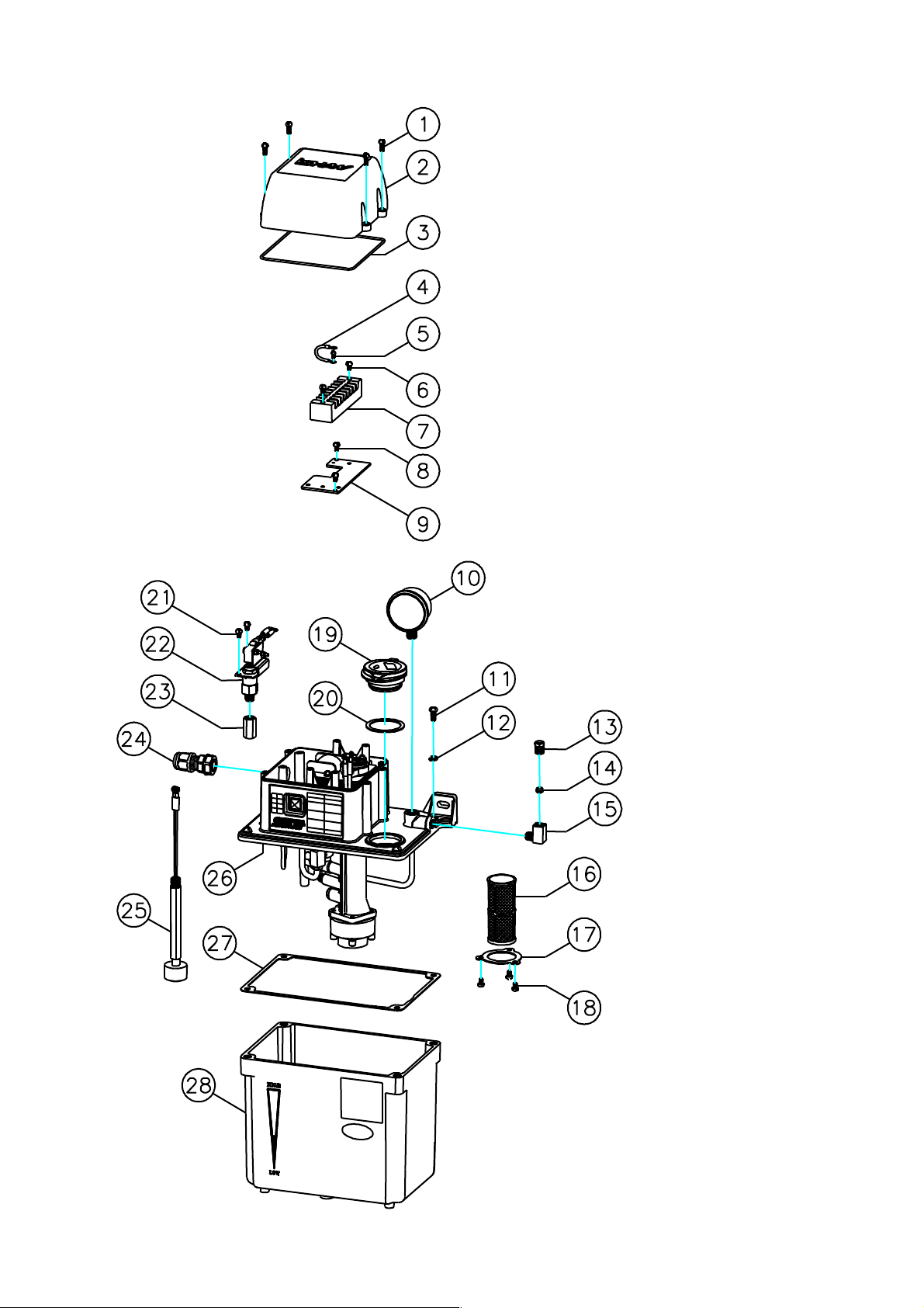
3-2 Parts of lubricator (PE-6003)

8 - 25
No. Description
1Philips screw M4*P0.7*10L
2Top cover of electronic box
3O-ring Ø2*Ø129.5 (S130)
4Wiring(yellow/green)set-CE grounding 130L
5Philips screw M3*P0.5*10L
6Philips screw M4*P0.7*10L
7Terminal plate 8P
8Philips screw M4*P0.7*6L
9Fixing plate for terminal plate
10 Pressure gauge 35kg*PT1/8*1.5" (kg/MPa)
11 Philips screw M5*P0.8*12L
12 Spring washer Ø5
13 Compression bushing Ø4
Compression bushing Ø6
14 Compression sleeve Ø4
Compression sleeve Ø6
15 Straight adaptor Ø4*1/8
Straight adaptor Ø6*1/8
16 Inlet filter (60 mesh)
17 Fixing sheet for inlet filter
18 Philips screw M4*P0.7*6L
19 Set of tank-cap
20 Seal of tank-cap
21 Philips screw M4*P0.7*10L
22 Pressure switch 12-9kg (for PE-60,70,80 series)
23 Connector Ø6XPS1/8
24 Cable gland(black) Ø22
25 Set of float switch
26 Upper module of PE-6003 (110V).
Upper module of PE-6003 (220V).
27 Packing for oil tank 3L
28 PE-6003 oil tank with stickers
9 - 25
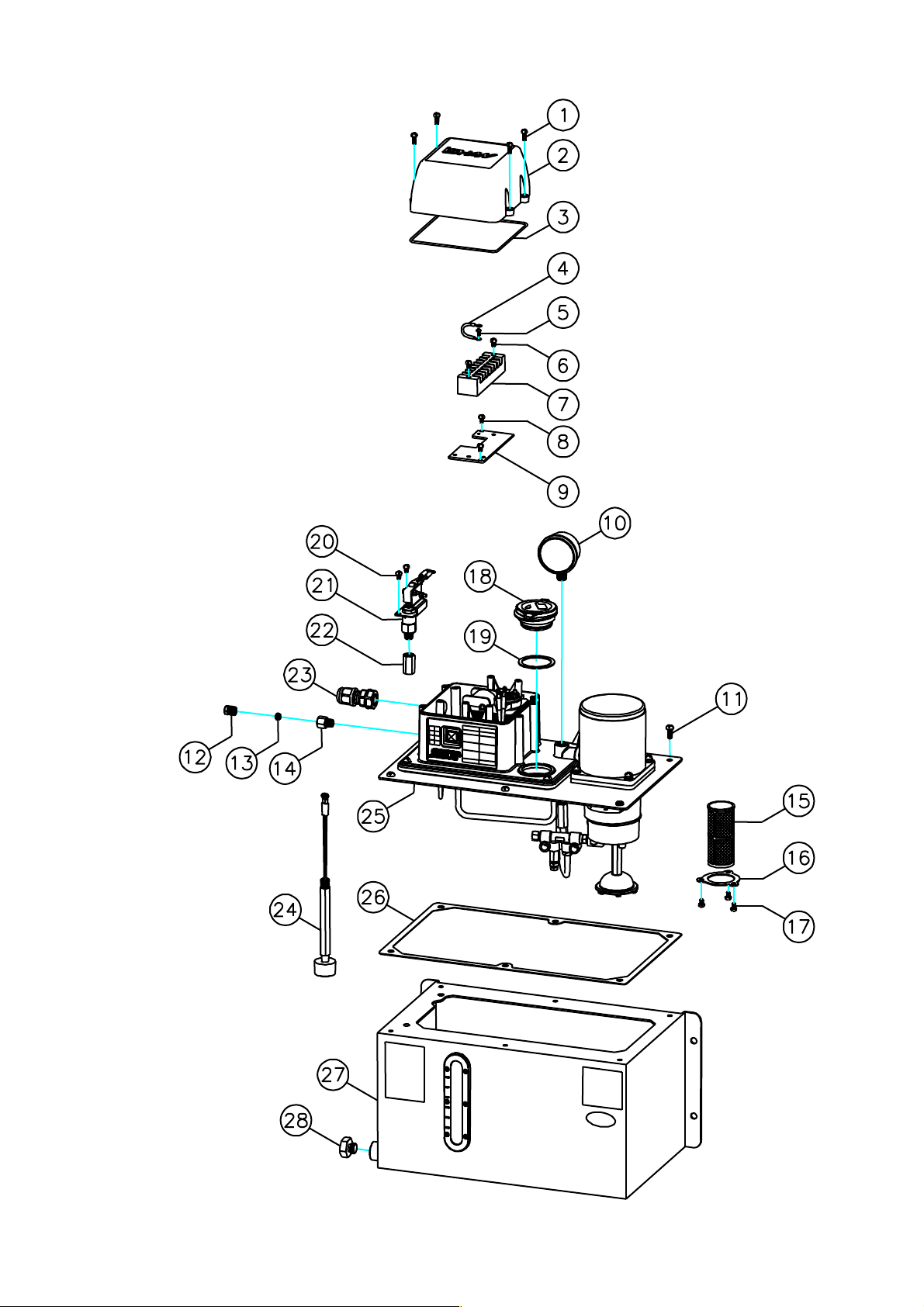
Parts of lubricator (PE-7008)

10 - 25
No. Description
1Philips screw M4*P0.7*10L
2Top cover of electronic box
3O-ring Ø2*Ø129.5 (S130)
4Wiring(yellow/ green)set-CE grounding 130L
5Philips screw M3*P0.5*10L
6Philips screw M4*P0.7*10L
7Terminal plate 8P
8Philips screw M4*P0.7*6L
9Fixing plate for terminal plate
10 Pressure gauge 35kg*PT1/8*1.5" (kg/MPa)
11 Philips screw M5*P0.8*12L
12 Compression Bushing Ø4
Compression Bushing Ø6
13 Compression Sleeve Ø4
Compression Sleeve Ø6
14 Straight adaptor Ø4*1/8
Straight adaptor Ø6*1/8
15 Inlet filter (60 mesh)
16 Fixing sheet for Inlet filter
17 Philips screw M4*P0.7*6L
18 Set of tank-cap
19 Seal of tank-cap
20 Philips screw M4*P0.7*10L
21 Pressure switch 12-9kg (for PE-60,70,80 series)
22 Connector Ø6XPS1/8
23 Cable gland(black) Ø22
24 Set of float switch
25 Upper Module of PE-7008(110V)
Upper Module of PE-7008(220V)
26 Packing for oil tank (for 6L/8L)
27 PE-7008 oil tank with stickers
28 Plug set for oil discharge

11 - 25
Parts of lubricator (PE-8008)

12 - 25
No. Description
1Philips screw M4*P0.7*10L
2Top cover of electronic box
3O ring Ø2*Ø129.5 (S130)
4Wiring(yellow/ green) set-CE grounding 130L
5Philips screw M3*P0.5*10L
6Philips screw M4*P0.7*10L
7Terminal plate 8P
8Philips screw M4*P0.7*6L
9Fixing plate for terminal plate
10 Pressure gauge 35kg*PT1/8*1.5" (kg/MPa)
11 Philips screw M5*P0.8*12L
12 Compression busing Ø4
Compression busing Ø6
13 Compression Sleeve Ø4
Compression Sleeve Ø6
14 Straight adaptor Ø4*1/8
Straight adaptor Ø6*1/8
15 Inlet filter (60 mush)
16 Fixing plate for inlet filter
17 Philips screw M4*P0.7*6L
18 Set of tank-cap
19 Seal of tank-cap
20 Philips screw M4*P0.7*10L
21 Pressure switch 12-9kg (for PE-60,70,80 series)
22 Connector Ø6XPS1/8
23 Cable gland(black) Ø22
24 Set of Float switch
25 Upper module of PE-8008(110V).
Upper module of PE-8008 (220V).
26 Packing for oil tank (for 6L/8L)
27 PE-8008 oil tank with stickers
28 Plug set of oil discharge
13 - 25
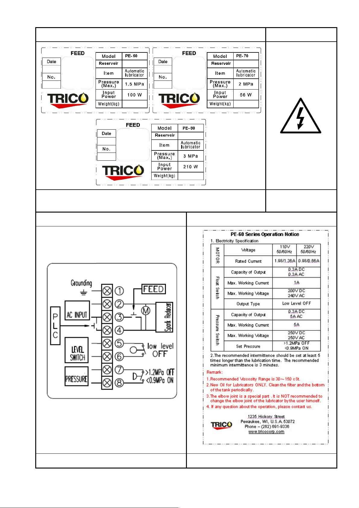
3-3 Label
Label Danger
Right front side of control box
Outside of the electrical
control box top cover
Wiring Diagram Operation Notice (PE-60 Series)
Inside of the e
lectrical control box top cover
Left side of the oil tank

14 - 25
Operation Notice (PE-70 Series)
Operation Notice (PE-80 Series)
Left side of the oil tank
Left side of the oil tank
15 - 25
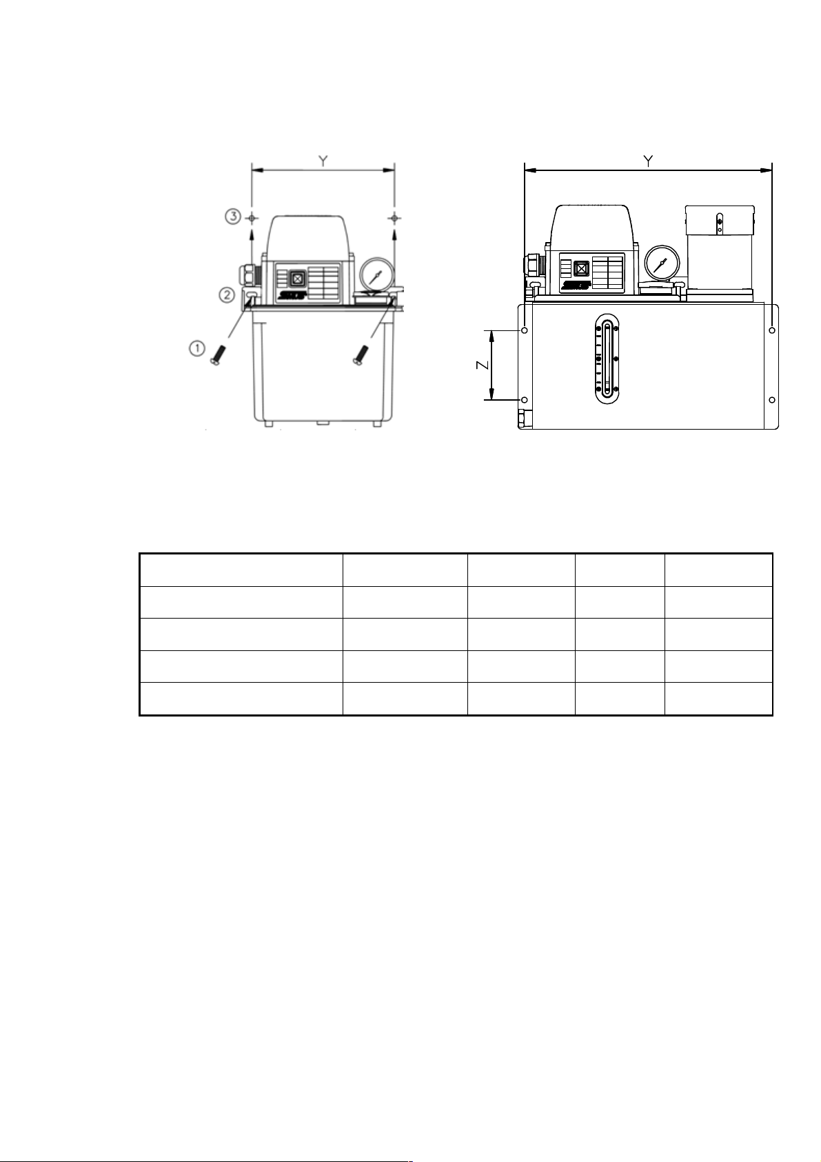
3-4 Installation
3-4.1 Mounting of the system
(Fig. B)
(Fig. C)
1. Mount the system on the machine fixing holes2 by fastening it with two screws (M6)1
at the upper lid holes 3
2. The distance of machine fixing holes is Y and Z as below listed
Model
Tank Capacity
Y Z Remark
PE-60 series 3L 190~205 N/A (Fig. B)
PE-60 series 4L 232~284 N/A (Fig. B)
PE-60, 70 series 6L 339 95 (Fig. C)
PE-70, 80 series 8L 339 95 (Fig. C)

16 - 25
3-4.2 Lubricant filling
Remove the oil tank cap and fill the tank with
clean lubricant at the level of 80% of the tank
height (Fig. D).
NOTE
Approved lubricant viscosity
MODEL
Viscosity Range
PE-60 series 30~150cSt
PE-70 series 30~250cSt
PE-80 series 30~250cSt
(Fig. D)
Viscosity higher (lower) than recommended viscosity range may result the burn down
(insufficient pressure) of the
lubrication systems.
Use new lubricant only.
3-4.3 Oil pipe connection (including related parts list)
PE-60 series parts list
No.
Item Specification
Q’ty
Ø4
1
Compression bushing
Ø6
1
Ø4
2
Compression sleeve Ø6
1
Ø4×1/8
3
Straight adaptor
Ø6×1/8
1
Ø4
4
Aluminum Pipe
(Reference only)
Ø6
1
(Fig. E)
Operation
(Fig. E)
a. Check the parts first
b. Remove the compression bushingand compression sleeveout of the outlet
adaptor.
c. Inset the end of the oil pipe into the compression bushingand compression sleeve
and connect with the outlet adaptor
d. The overhead of the pipeafter inserting the compression sleeveneeds more
than 1mm.
e. Align and tighten the pipewith the compression bushingto avoid the leaking.
If the pipeis loosen, remove the compression bushingand compression
(PE-60 series)

17 - 25
PE-70, PE-80 series parts list
No.
Item Specification
Q’ty
Ø4
1
Compression bushing
Ø6
1
Ø4
2
Compression sleeve Ø6
1
Ø4×1/8
3
Straight adaptor
Ø6×1/8
1
Ø4
4
Aluminum Pipe
(Reference only)
Ø6
1
(Fig. F)
Operation
(Fig. F)
a. Check the parts first.
b. Remove the compression bushingand compression sleeveout of the outlet
adaptor.
c. Inset the end of the oil pipe into the compression bushingand compression
sleeveand connect with the outlet adaptor
d. The overhead of the pipeafter inserting the compression sleeveneeds
more than 1mm.
e. Align and tighten the pipewith the compression bushingto avoid the
leaking.
If the pipeis loosen, remove the compression bushingand compression
sleevethen connect the pipe again.
3-4.4 Installation of power and alarm
Note !! The installation of a fuse between the power supply and Trico Corporation
centralized lubrication systems is strongly recommended !!
Operation
Note !! Make sure the power cable is disconnected before the installation.
a. Remove the e
lectrical control box cover
of the e
lectrical control box
connection box
(Fig. G).
b. Loosen the cable gland (Fig. H).
c. Insert the cable into the e
lectrical control box
through the cable gland hole (Fig. I).
(PE-70 series)
(PE-80 series)

18 - 25
(Fig. G) (Fig. H)
(Fig I) (Fig. J)
(Fig. K)
d.Connect the power cable as the wiring diagram (Fig. J), then connect the ground cable.
e. The function of float switch is to release the warning message to stop the machine
when the lubricant is at the low level.
f. If you need interval lubrication function, the lubricator needs to manage ON/ OFF
through timer function. It is controlled by an external controller.
g. Float switch terminals are available (Standard connection is at NC and COM).
h. Close the cover after connecting all cables.
i. To protect the cable from being pulled out of the box and disconnected from the ports,
fasten the gland again (Fig. K).
j. Connect the lubricator with power supply properly and the lubricator will starts with
operation.

19 - 25
4. Instruction
4-1 Operation
If lubrication is needed during the intermittence, please push the FEED button.
Make sure the power cable is disconnected before the installation or removal of the
system. Turn ON the power after more than twenty seconds of turning OFF.
The adaptor of the system for connecting the pipe is without one-way function for the
system. It is prohibited for changing to non-original set-up to avoid malfunction.
Note !! The set-up of intermittent time needs to be above five times than lubrication
time to prolong the life of the motor(the recommended minimum intermittent
time is 3-minute).
4-2 Lubricant Filling
Always keep the oil level between the level of 30% and 80% of the tank height. Float switch
will output signal when the remainder of the lubricant drops below the height if the float
switch, and it is time to fill the tank. Remove the oil tank cap (Fig. D), you can fill the
tank.
Attention!
Recycled lubricant is PROHIBITED
5. Maintenance
Trico Corporation centralized lubrication systems are of low maintenance. However, related
connection needs to be reviewed if properly fitted to secure the proper function of the system.
Please clean periodically the oil tank of Trico Corporation
centralized lubrications. If the user
wants to clean the tank, please TURN OFF the system first and remove the bolts on the tank
to separate the tank for cleaning. After cleaning the tank, please fasten the bolts to fix the
tank.
Please follow below requirements,
Restart the lubricator after 20 sec. of turning off to stabilize the performance of the lubricator.
It is prohibited for changing to non-original set-up to avoid malfunction.
The One-way adapter cannot be applied.

20 - 25
6 Faults
!Only original
Trico Corporation centralized lubrication systems spare parts are used for Trico
Corporation centralized lubrication systems. It is prohibited for changing to non-original spare
parts.
!
TURN OFF the power before any checking or maintenance Faults / Fault finding
Malfunction Possible cause Rectification
Impermissible lubricant Revised to the lubricant of suitable
viscosity
Float switch fails to work Replace with a new float switch.
1.Check if power cable is
connected in mistake or incorrect
power input.Motor fails to work
2. The repair needs to be done by
authorized personnel.
No lubricant is
discharged from
the system
Insufficient lubricant Refill the tank
Oil suction set is blocked. Clean the setInsufficient
lubricant
discharged Impermissible lubricant Revised to the lubricant of suitable
viscosity
Leaking at the
connection of the
pipe and the
lubricator
Incorrect installation
The pipe must be inserted into the
compression sleeve and at least
1mm over the end of the
compression sleeve further into the
adapter.
After disassembling the outlet, checking if the lubricant is
discharged.
If YES, the piping could be
blocked or leaking. Find out and replace the part of the
pipe in problem.
Motor runs but no
lubricant is
discharged from the
system
If NO, the causes could be,
1. Gear pump is jammed
2. Motor is out of function
The repair needs to be done by
authorized personnel.
1. Piping leaks 1.Find out and replace the part of
the pipe in problem.
2. Motor is out of function 2. The repair needs to be done by
authorized personnel.
Abnormal message
is released
3. Gear pump is jammed 3. The repair needs to be done by
authorized personnel.
Note: If the lubricator is sent to repair, please ensure the lubricant is completely removed to
This manual suits for next models
2
Table of contents
Other Trico Lubrication System manuals

Popular Lubrication System manuals by other brands


Norgren
Norgren 10-028-037 Installation & maintenance instructions

Quantum
Quantum M1500 instructions

Groeneveld
Groeneveld Multiline AC F219157R03 installation manual

LUBMANN
LUBMANN ALP01 product manual

NTN-SNR
NTN-SNR Ready Booster 60 operating instructions

Simatec
Simatec simalube 60 User manual & technical information


