manuals.online logo
Brands
  1. Home
  2. •
  3. Brands
  4. •
  5. Lincoln
  6. •
  7. Lubrication System
  8. •
  9. Lincoln SL-11 Series User manual

Lincoln SL-11 Series User manual

SPECIFICATIONS
For dispensing fluid lubricant or grease.
Adjustable from .05 cu. in. to .5 cu. in.
MATERIALS
Packings are compatible with common synthetic and
petroleum based lubricants.
OPERATING PRESSURE
1850 p.s.i. Minimum
2500 p.s.i. Recommended
3500 p.s.i. Maximum
300 p.s.i. Maximum Recharge Pressure
Model No. 85497
SL-11 INJECTOR
Series "A"
Copyright 1995
Printed in U.S.A.
One Lincoln Way
St. Louis, Missouri 63120-1578
(314) 679-4200
A PENTAIR COMPANY
SectionSection
SectionSection
Section
PagePage
PagePage
Page -C8-C8
-C8-C8
-C8
-254A-254A
-254A-254A
-254A
FORM 402579FORM 402579
FORM 402579
Jan. 95
Continued on page 3
Description:
SL-11 series injectors are designed for
applications requiring large volumes of grease.
They are supplied with packings compatible with
synthetic and petroleum based greases. Available
only as a single unit with 1/2 NPT inlet, and 1/4
NPT outlet. The SL-11 injector incorporates a
hydraulic filler fitting for priming the feed line.
Output adjustment:
The SL-11 injectors output is adjusted with the
hex screw on top of the unit. A minimum output
of approx. .050 cu. in. is obtained when the
adjusting screw is turned clockwise, into the
injector, hand tight. To obtain the maximum
output of .50 cu. in., start at the minimum setting
and turn the screw counterclockwise 12 3/4
turns, out of the injector. Each turn of the screw
is equal to .043 cu. in. in output. When the
injector is adjusted to a half turn open or less,
output from the injector should be verified.
Disassembly Instructions:
1. Remove the adjustment adapter (item #3)
from the top of the injector. Remove the piston
assembly (item #8), spring (item #9), and spacer
(item #19) from inside the injector.
2. Remove the inlet adapter (item #18) from the
bottom of the injector. To remove the slide valve
assembly (item #11), turn injector over, with the
top pointing down. If the slide valve does not
fall out, it may be pushed out of the slide valve
packings (items #13) with a blunt object, being
careful not to scratch or cut the packings in the
slide valve body.
3. To remove the valve body (item #16):
a. If it sticks in the inlet adapter (item #18),
gently pry the valve body out of the inlet adapter
using a small round rod. Place the rod into a
hole in the side of the valve body and pry against
the face of the inlet adapter. Work one hole at a
time, working around the valve body until it is
freed.
18
1/4 NPT
OUTLET
10
7
6
2
1
4
SLIDE VALVE DETAIL
Item
No. Description Qty Part
No.
1
2
3
4
5
6
7
8
9
10
11
12
13
14
15
16
17
18
19
Adjusting Screw
Lock Nut
Adjustment Adapter
O-Ring (viton)
Washer
Packing (viton)
O-Ring (viton)
Piston Ass'y.
Plunger Spring
FittingAss'y.
Slide Valve Ass'y.
Spacer
Packing (Hytrel)
Back-up Ring (teflon)
O-Ring (viton)
Valve Body
Injector Body
Inlet Adapter
Spacer
1
1
1
2
1
1
1
1
1
1
1
2
2
2
2
1
1
1
1
244628
51039
244613
*
*
*
*
24462212
*
90471
*
**
*
*
*
**
244610
244611
244626
SERVICE PARTS
INJECTOR SERVICE KITS:
Part No. 244633 Injector Repair Kit
contains all normal wear parts for this
injector. Indicated with the single star
(*), above.
Part No. 244634, Valve Body Ass'y.
contains the slide valve body and spacers
for this injector. Indicated with the
double star (**), above.
12
5
Torque to
165 ft-lbs.
3
Torque to
165 ft-lbs.
Page 2
13
2 3/16"
11
19
9
5/8"
9 15/32"
2 3/4"
14
14
16
12
15
4
8
b. If the valve body sticks in the injector
body, turn injector right side up and use a 7/16
to 1/2" brass or wooden dowel rod to gently tap
the valve body out of the injector body.
4. To remove the indicator stem packing (item
#6) from the adjustment adapter (item #3),
remove the adjustment screw (item #1) from the
adjustment adapter. Use a blunt object, such as
a wooden dowel, placed into the adjustment
screw hole to gently push the washer (item #5)
and packing out of the adjustment adapter, from
the bottom side.
Reassembly Instructions:
1. Clean all injector components, and carefully
inspect all parts for wear, replacing parts as
necessary. (See trouble shooting chart for
guidance.)
2. Start reassembly by pre-assembling the valve
body, by installing the two packings (items #13)
into the valve body (item #16), followed by the
spacers (items #12). Install the O-rings (items
#15) and back-up rings (items #14) into the
grooves on the outside of the valve body. (See
valve body detail, for correct assembly
sequence.) Apply a liberal amount of grease to
O-rings on outside of valve body, and gently
push the pre-assembled valve body into the inlet
adapter (item #18).
3. Install O-ring (item #4) onto the inlet adapter
(item #18). Install inlet adapter into the injector
body, and tighten by hand assuring that the valve
body slides into it's respective bore in the
injector body. Tighten the inlet adapter to the
injector body.
4. Apply a liberal coating of grease to the slide
valve assembly (item #11). Insert the slide valve
assembly through the top of the injector into the
valve body packings (item #13), which should
already be installed into the bottom of the
injector body. Apply a liberal coating of grease
to the piston bore in the injector body. Drop in
the spring (item #9), and place the spacer (item
#19) inside the spring.
5. Install the O-ring (item #7) on the piston
assembly (item #7). Apply a liberal coat of
grease to the piston, O-ring, and indicator rod.
Place the piston assembly into the piston bore of
the injector body. Install O-ring on adjustment
adapter (item #3). Install washer (item #5) and
packing (item #6) into adjustment adapter.
Apply grease to the O-ring on the adjustment
adapter and the mating bore in the top of the
injector body. Carefully slide the pre-assembled
adjustment adapter over indicator pin on the
piston assembly (item #8), screw adjustment
adapter into the injector body hand tight, then
tighten with wrench. Reinstall adjustment screw
(item #1) into adjustment adapter.
Page 3
RETAINTHISINFORMATIONFORFUTUREREFERENCE
When ordering replacement parts, list: Part Number, Description, Model Number, and Series Letter.
LINCOLN provides a Distributor Network that stocks equipment and replacement parts.
CONDITION POSSIBLE CAUSE CORRECTIVE ACTION
External leakage at
body.
Damaged or worn body O-rings. Replace O-rings (Item #4)
External leakage at
fitting assembly.
Loose cap
Damaged fitting
Tighten cap
Replace fitting (Item #10)
External leakage at
indicator rod.
Worn or damaged indicator rod
packing.
Worn or damaged indicator rod.
Replace packing (Item #6)
Replace piston ass'y. (Item #8)
Lubricant volume to
bearing LOW.
Output adjustment screw setting
incorrect.
Worn or damaged LOWER slide
valve seal.
Worn or damaged LOWER slide
valve body O-ring.
Plunger spring broken or worn.
Adjust to proper setting and lock
with lock nut.
Replace slide valve seals (Item
#13)
Replace O-rings and back-up
rings (Items #15 & #14)
Replace spring (Item #9)
Lubricant volume to
bearing too HIGH.
Output adjustment screw setting
incorrect.
Worn or damaged UPPER slide
valve seal.
Worn or damaged UPPER slide
valve body O-ring.
Plunger spring broken.
Worn or damaged slide valve
ass'y.
Adjust to proper setting and lock
with lock nut.
Replace slide valve seals (Item
#13).
Replace O-rings & back-up rings
(Items #15 & 14).
Replace spring (Item #9).
Replace slide valve ass'y. (Item
#11).
Trouble Shooting Chart

This manual suits for next models

1

Other Lincoln Lubrication System manuals

Lincoln SKF Centro-Matic Instruction Manual

Lincoln

Lincoln SKF Centro-Matic Instruction Manual

Lincoln QLS 401 User manual

Lincoln

Lincoln QLS 401 User manual

Lincoln Quicklub Series Operating instructions

Lincoln

Lincoln Quicklub Series Operating instructions

Lincoln 4100 User manual

Lincoln

Lincoln 4100 User manual

Lincoln QUICKDATA 233 User manual

Lincoln

Lincoln QUICKDATA 233 User manual

Lincoln 549 User manual

Lincoln

Lincoln 549 User manual

Lincoln 2435 Instruction Manual

Lincoln

Lincoln 2435 Instruction Manual

Lincoln 85418 User manual

Lincoln

Lincoln 85418 User manual

Lincoln SKF 84803 Instruction Manual

Lincoln

Lincoln SKF 84803 Instruction Manual

Lincoln 85562 User manual

Lincoln

Lincoln 85562 User manual

Lincoln SKF CLK User manual

Lincoln

Lincoln SKF CLK User manual

Lincoln SKF KFU2 Series User manual

Lincoln

Lincoln SKF KFU2 Series User manual

Lincoln QLS 421 User manual

Lincoln

Lincoln QLS 421 User manual

Lincoln 85418 Instruction Manual

Lincoln

Lincoln 85418 Instruction Manual

Lincoln Cobra 501 User manual

Lincoln

Lincoln Cobra 501 User manual

Lincoln Quicklub 203 Series User manual

Lincoln

Lincoln Quicklub 203 Series User manual

Lincoln QLS 301 User manual

Lincoln

Lincoln QLS 301 User manual

Lincoln Quicklub 223 User manual

Lincoln

Lincoln Quicklub 223 User manual

Lincoln QLS 401 User manual

Lincoln

Lincoln QLS 401 User manual

Lincoln SKF TLMR 101 User manual

Lincoln

Lincoln SKF TLMR 101 User manual

Lincoln QLS 311 User manual

Lincoln

Lincoln QLS 311 User manual

Lincoln 3675 User manual

Lincoln

Lincoln 3675 User manual

Lincoln B Series User manual

Lincoln

Lincoln B Series User manual

Lincoln C Series Owner's manual

Lincoln

Lincoln C Series Owner's manual

Popular Lubrication System manuals by other brands

Schneider Airsystems FP-M Original operating manual

Schneider Airsystems

Schneider Airsystems FP-M Original operating manual

Atlas Copco CLG 10 Safety and operating instructions

Atlas Copco

Atlas Copco CLG 10 Safety and operating instructions

ABB ZSD 2020 OVERHAUL INSTRUCTIONS

ABB

ABB ZSD 2020 OVERHAUL INSTRUCTIONS

Alemlube 51037M Owner technical manual

Alemlube

Alemlube 51037M Owner technical manual

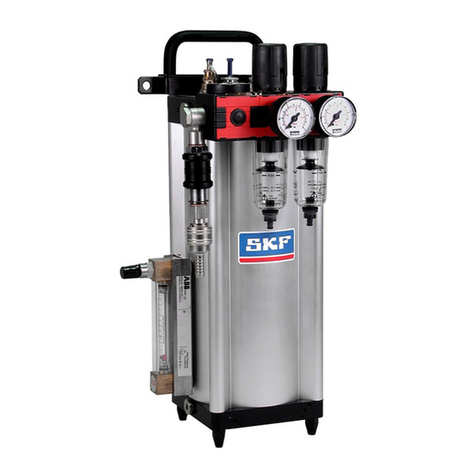
SKF LUBRILEAN Basic operating manual

SKF

SKF LUBRILEAN Basic operating manual

Groeneveld CompAlube General manual

Groeneveld

Groeneveld CompAlube General manual

Azbil MC9 Series instruction manual

Azbil

Azbil MC9 Series instruction manual

IMI NORGREN L64C Installation & maintenance instructions

IMI NORGREN

IMI NORGREN L64C Installation & maintenance instructions

Perma NOVA 65 Operationg instructions

Perma

Perma NOVA 65 Operationg instructions

SKF LINCOLN ZPU 01 Version E installation instructions

SKF

SKF LINCOLN ZPU 01 Version E installation instructions

Groeneveld MultiLine SFi Operation & maintenance manual

Groeneveld

Groeneveld MultiLine SFi Operation & maintenance manual

Bijur Delimon TMD-5 manual

Bijur Delimon

Bijur Delimon TMD-5 manual

Viper Mid MKII Assembly & operation manual

Viper

Viper Mid MKII Assembly & operation manual

LUBRIQUIP Trabon Series Operation and service instructions

LUBRIQUIP

LUBRIQUIP Trabon Series Operation and service instructions

manuals.online logo
manuals.online logoBrands
  • About & Mission
  • Contact us
  • Privacy Policy
  • Terms and Conditions

Copyright 2025 Manuals.Online. All Rights Reserved.