TRIGA TR-B200S-LF-WH User manual

TR-B200S-LF-WH, TR-B200S-LF-IV
Low Frequency Intelligent Sounder Base
INSTALLATION AND MAINTENANCE INSTRUCTIONS
BEFORE INSTALLING
Read Applications Guide for System Smoke Detectors,which provides
detailed information on sensor spacing, placement, zoning, wiring, and
special applications. NFPA 72 and NEMA guidelines should be observed. The
National Fire Alarm Code, NFPA 72, requires effective January 1, 2014, that
audible appli-ances installed in sleeping areas produce a low frequency
alarm signal that shall be a square wave or provide equivalent awakening
ability with a funda-mental frequency of 520 Hz +/– 10%.
NOTE: Triga Series sounder bases are not compatible with remote test
capable Triga Series detectors.
NOTICE: This manual should be left with the owner/user of this equipment.
IMPORTANT: The detector used with this base must be tested and
maintained regularly following NFPA 72 requirements. The detector should
be cleaned at least once a year.
GENERAL DESCRIPTION
The TR-B200S-LF-WH and TR-B200S-LF-IV sounder bases are used with
ad-dressable detector heads. Refer to the appropriate manual for more
informa-tion on sensors.
The TR-B200S-LF-WH/TR-B200S-LF-IV low frequency sounder base
generates a low frequency tone around 520 Hz. Studies have shown that low
frequency audible devices that operate around 520 Hz are more effective in
waking indi-viduals in sleeping areas.
The sounder base is capable of producing a variety of tone patterns,
includ-ing the distinctive three-pulse temporal pattern (ANSI Temporal 3)
fire alarm signal now required by NFPA 72 for commercial and residential
applications. The TR-B200S-LF-WH/TR-B200S-LF-IV offers maximum
flexibility in configu-ration and operation to meet or exceed the
requirements of UL268 and UL464 for Continuous, Temporal 3 and March
time patterns. The temporal 4 pattern meets all requirements of UL268 and
UL2075, as well as, private mode setting of UL 464.
The TR-B200S-LF-WH/TR-B200S-LF-IV can be commanded by the Fire
Alarm Control Panel (FACP) to adopt the address of the attached sensor
head, but as a unique device type on the loop. By using the address, the
FACP can com-mand an individual sounder base to activate, or a group of
sounders in a suite or other multi-room configuration. The command set
from the panel can be tailored to the specific event, allowing selection of
volume, tone, and group. The device offers two volume levels: 75 dBA and
85 dBA. The available tones are Continuous, ANSI Temporal 3, ANSI
Temporal 4, and March Time. In ad-dition, some panels will offer the ability
to command a custom tone pattern. Refer to the appropriate FACP manual
for more information.
SPECIFICATIONS
Base Diameter: 6.875" (17.46 cm)
Base Height (less sensor): 2.0" (5.08 cm)
Weight: 0.6 lb. (272 g)
Operating Temperature Range: Refer to the applicable sensor’s operating temperature range provided in the sensor’s installation manual.
Operating Humidity Range: 10% to 93% relative humidity (non-condensing)
External Supply Electrical Ratings
External Supply Voltage: 16 to 33 VDC (VFWR)
Standby Current: 550 μA maximum VDC
Alarm Current: High volume setting: 70 mA maximum @ 33.0 VDC Low volume setting: 15 mA maximum @ 33.0 VDC
90 mA maximum @ 24.0 VDC 20 mA maximum @ 24.0 VDC
140 mA maximum @16.0 VDC 25 mA maximum @ 16.0 VDC
SLC Electrical Ratings
SLC Operating Voltage: 15 to 32 VDC
SLC Standby Current: 300 μA maximum (base only, refer to applicable sensor specification)
Sound Output
High Volume: Greater than 85 dBA minimum measured in a UL reverberant room at 10 feet (3.1m), 24 Volts (in continuous tone)
Low Volume: Greater than 75 dBA minimum measured in a UL reverberant room at 10 feet (3.1m), 24 Volts (in continuous tone)
In addition, the TR-B200S-LF-WH/TR-B200S-LF-IV is equipped with the cir-
cuitry to recognize the System Sensor synchronization protocol, enabling the
sounder base to be used as a component of the general evacuation signal –
producing an NFPA 72 compliant Temporal 3 pattern in synchronization with
compatible listed notification devices. This requires connection to a power
supply capable of generating the System Sensor synchronization pulses, a
FACP NAC output configured to System Sensor synchronization protocol, or a
separate synchronization module.
The sounder base is intended for use with intelligent systems. In addition to
being connected to the SLC, the sounder base requires a connection to either
24 VDC constant power or a NAC circuit, depending on the FACP and intended
use. The connections for 24V constant/NAC power and the communication
loop are isolated to prevent electrical interaction between them.
When connected to a NAC, power is supervised via the NAC circuit supervi-
sion while in standby mode (EOL resistor required for Class B operation).
When activated, the TR-B200S-LF-WH/TR-B200S-LF-IV provides supervision
of NAC power. (See Figure 5.)
When using a FACP equipped with a “sounder base standby power monitor-
ing” mode and constant 24 V power, power supervision EOL devices (supervi-
sion relays and resistors) should not be used. (See Figure 4.) In this case, the
TR-B200S-LF-WH/TR-B200S-LF-IV will provide supervision in both standby
and alarm/active mode. Refer to FACP installation documentation to deter-
mine if this mode is available. If your FACP does not support this mode or you
choose not to use it, power supervision relays and EOL resistors are required
to provide supervision in standby mode.
NOTE: If the FACP’s “sounder base standby power monitoring” mode is en-
abled, connecting TR-B200S-LF-WH/TR-B200S-LF-IV low frequency sounder
bases to the NAC will result in power supervision failure when in standby.
Only connect TR-B200S-LF-WH/TR-B200S-LF-IV low frequency sounder bases
to constant 24 V power in this case. Refer to the FACP manual for maximum
allowable number of units per loop.
NOTE: For NFPA72 Installations, the Temporal 3 tone at high volume should
be used for public mode evacuation. The use of other tone styles and low
volume level will be at the discretion of the local Authority Having Jurisdic-
tion (AHJ).
NOTE: When not used as a supplementary evacuation system, the external 24
VDC supply shall be treated as a component of the main power supply system
and shall fall under the requirements of the main power supply system per
NFPA 72.
I56-4151TRG-005
This model is compatible with Models MDL, MDL3R, MDLW, MDL3W and SYNC-1
TRIGA Life Safety Systems, LLC
7600 Olde Eight Rd.
Hudson, Ohio 4426-1057
base/sensor cross reference chart ==>base/sensor cross reference chart ==>
Source:
For a list of compatible sensors, refer to the Sys-
tem Sensor website at www.systemsensor.com.
1/29/2021
For a complete list of compatible sensors, refer to
the Base/Sensor Cross Reference Chart at triga-
global.com.
4/23/2021 DELETE: For a complete list of compatible4/23/2021 DELETE: For a complete list of compatible
bases, refer to the Base/Sensor Cross Reference Chart atbases, refer to the Base/Sensor Cross Reference Chart at
trigaglobal.com.trigaglobal.com.
1 I56-4151TRG-005
4/22/2021
WIRING GUIDELINES
All wiring must be installed in compliance with the National Electrical Code
and the local codes having jurisdiction and must not be of such length or wire
size which would cause the base to operate outside of its published specifica-
tions. The conductors used to connect smoke sensors to control panels and
accessory devices should be color coded to reduce the likelihood of wiring
errors. Improper connections can prevent a system from responding properly
in the event of a fire.
Wire sizes up to 12 AWG (2.5 mm2) may be used with the base. The sounder
base will be shipped with the screw terminals set for 14 AWG wiring. If 12
AWG wire is to be used, back out the screws to allow the wire to fit beneath
the clamping plates. For best system performance, the power (+ and -) wires
and the communication circuit wires should be twisted pair or shielded cable
installed in a separate grounded conduit to protect the communication loop
from electrical interference.
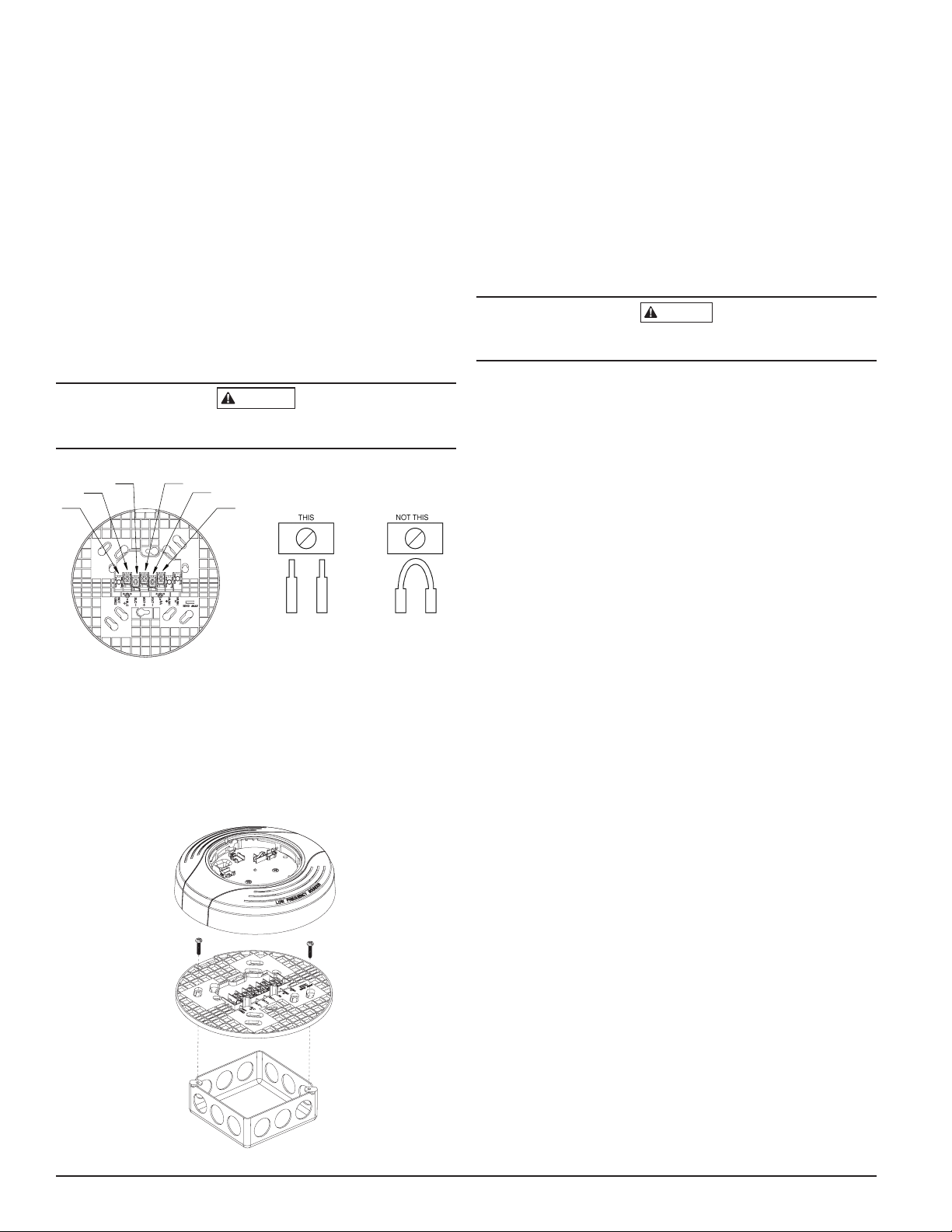
Make wire connections by stripping about 3/8" (10 mm) of insulation from the
end of the wire. Then, slide the bare end of the wire under the appropriate
clamping plate (See Figure 1), and tighten the clamping plate screw. Do NOT
loop the wire under the clamping plate. (See Figure 2.) The wiring diagram for
a typical 2-wire intelligent system is shown in Figure 4.
CAUTION
For system monitoring - for terminals 2, 3, 4, and 5, do not use looped wire under
terminals. Break wire run as shown in Figure 2 to provide monitoring of connections.
FIGURE 1. FIGURE 2.
1
1
2
2
3
3
4
4
5
5
6
6
C0471-08 C0473-00
TR-B200S-LF-WH/TR-B200S-LF-IV TERMINALS
No. Function
1. Not Used
2. Positive (+) Comm. Line In and Out
3. Negative (-) Comm. Line In and Out
4. External Supply Positive (+)
5. External Supply Negative (-)
6. Remote Annunciator
FIGURE 3. MOUNTING
C0891-09
MOUNTING
Mount the TR-B200S-LF-WH/TR-B200S-LF-IV mounting plate directly to an
electrical box. The plate will mount directly to 4" (10.2cm) square (with and
without plaster ring), 4" (10.2cm) octagon, 3½" (8.9 cm) octagon, single gang
or double gang junction boxes.
1. Connect field wiring to terminals, as shown in Figure 1 and 2.
2. Attach the mounting plate to the junction box as shown in Figure 3.
3. To mount the sounder base, hook the tab on the sounder base to the groove
on the mounting plate.
4. Then, swing the sounder base into position to engage the pins on the
product with the terminals on the mounting plate.
5. Secure the sounder base by tightening the mounting screws.
6. Install a compatible smoke sensor as described in the installation manual
for the sensor.
CAUTION
Do not over tighten mounting plate screws; this may cause mounting plate
to flex.
TAMPER RESISTANT FEATURE
NOTE: Do not use the tamper-resist feature if the removal tool is to be used.
This detector base includes a tamper-resist feature that prevents its removal
from the base without the use of a tool. To activate this feature, break the tab
from the detector base as shown in Figure 7A. Then, install the detector. To
remove the detector from the base once the tamper-resist feature has been ac-
tivated, insert a small-bladed screwdriver into the slot from the top and press
down on the lever. (See Figure 7B). This allows the detector to be rotated
counterclockwise for removal. The tamper-resist feature can be defeated by
breaking and removing the plastic lever from the base. However, this prevents
the feature from being used again.
TESTING AND MAINTENANCE
Sensors and bases must be tested after installation and as an integral part of
a periodic maintenance program. Test the TR-B200S-LF-WH/TR-B200S-LF-IV
as follows:
NOTE: Before testing, notify the proper authorities that the smoke sensor
system is undergoing maintenance and, therefore, will be temporarily out of
service. Disable the system undergoing maintenance to prevent unwanted
alarms.
1. Via the FACP, command the individual TR-B200S-LF-WH/TR-B200S-LF-IV
to activate using the associated sensor address. That sounder base should
sound in approximately five seconds.
2. Via the FACP, command all TR-B200S-LF-WH/TR-B200S-LF-IV low fre-
quency sounder bases to activate using group communication to all associ-
ated addresses. All devices on the loop should sound, and if a temporal
tone is commanded, the tones can be synchronized to each other.
NOTE: Synchronization requires a power supply capable of producing the Sys-
tem Sensor synchronization pulses or a synchronization module.
When performing maintenance on connected smoke sensors, carefully note
the location and address of each removed sensor. When re-installed, the
TR-B200S-LF-WH/TR-B200S-LF-IV will confirm that address of the sensor
matches the address stored in the sounder base memory. If there is a mis-
match, this will be communicated to the FACP and the sounder base can be
commanded to chirp at regular intervals until the correct head is installed.
If a replacement head is installed or address changes are required,
the mismatch may be resolved at the panel by commanding the
TR-B200S-LF-WH/TR-B200S-LF-IV low frequency sounder base to re-enter its
address learning mode and adopting the address of the new sensor.
2 I56-4151TRG-005
4/22/2021
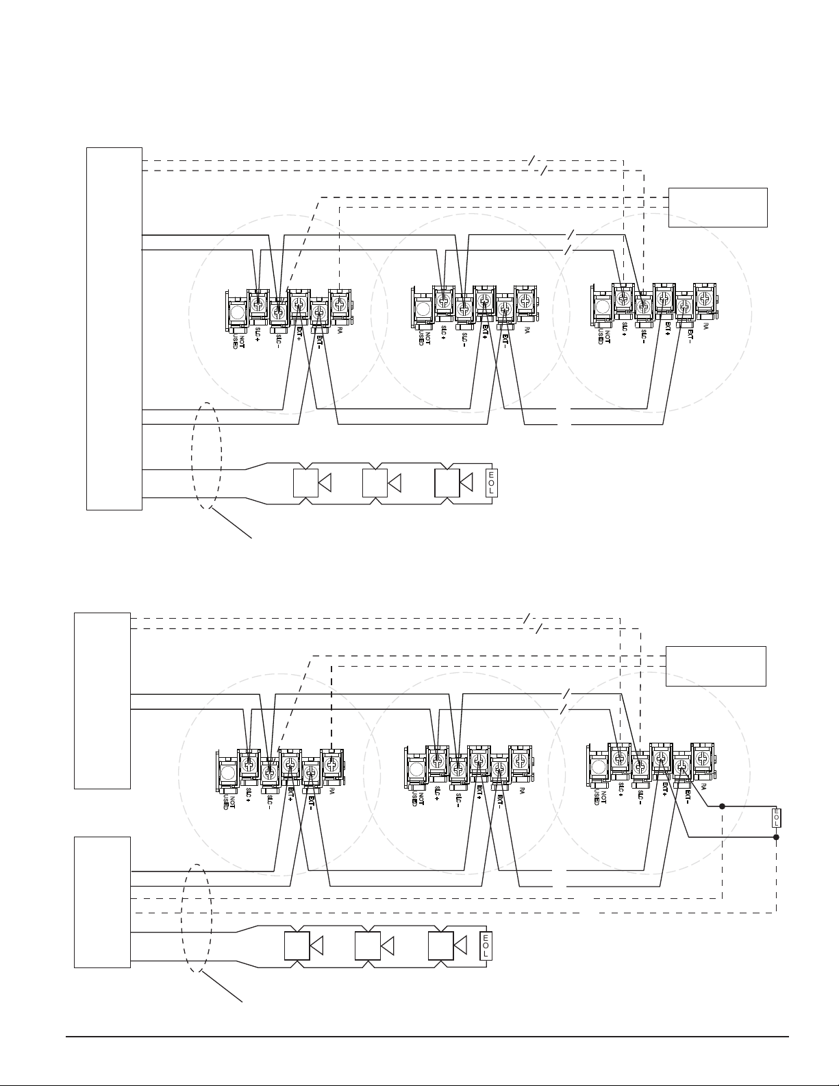
FIGURE 4. WIRING DIAGRAM
(CONNECTED TO 24V POWER USING COMPATIBLE FACP WITH “SOUNDER BASE STANDBY POWER MONITORING” ENABLED)
FIGURE 5. WIRING DIAGRAM (CONNECTED TO NAC OR 24V POWER; OPTIONAL EOL DEVICES FOR CONSTANT SUPERVISION)
(+) SLC
(–) SLC
(–) CONSTANT POWER
(–) NAC
(+) CONSTANT POWER
(+) NAC
U.L. LISTED COMPATIBLE
CONTROL PANEL
OPTIONAL REMOTE
ANNUNCIATOR MODEL
TR-RA100Z
CLASS A OPTIONAL WIRING
FIRST
SOUNDER
BASE
SECOND
SOUNDER
BASE
LAST
SOUNDER
BASE
NOT
USED
SLC +
EXT –
EXT +
RA
SLC –
NOT
USED
SLC +
EXT –
EXT +
RA
SLC –
NOT
USED
SLC +
EXT –
EXT +
RA
SLC –
(+) (+) (+)
(–) (–) (–)
EOL
A SEPARATE SYNCHRONIZATION MODULE MAY BE USED TO PROVIDE
THE SYNCHRONIZATION PULSES (SEE FIGURE 6)
/
/
HORN HORNHORN/STROBE
FIRST
SOUNDER
BASE
SECOND
SOUNDER
BASE
LAST
SOUNDER
BASE
NOT
USED
SLC +
EXT –
EXT +
RA
SLC –
NOT
USED
SLC +
EXT –
EXT +
RA
SLC –
NOT
USED
SLC +
EXT –
EXT +
RA
SLC –
(+) SLC
(–) SLC
(–) NAC OR CONSTANT POWER*
(+) NAC OR CONSTANT POWER*
(+) NAC
(–) NAC
OPTIONAL REMOTE
ANNUNCIATOR MODEL
TR-RA100Z
(+) (+) (+) EOL
A SEPARATE SYNCHRONIZATION MODULE MAY BE
USED TO PROVIDE THE SYNCHRONIZATION PULSES
HORNHORN/STROBE
UL LISTED COMPATIBLE
CONTROL PANEL
UL LISTED 24V
POWER SUPPLY
*WHEN USING 24V CONSTANT POWER
(AUX POWER), ADDITIONAL POWER
SUPERVISION RELAYS AND MODULES WILL
BE REQUIRED FOR PROVIDING SUPERVISION
WHEN THE SOUNDER BASES ARE INACTIVE.
CLASS A OPTIONAL WIRING
(–) (–) (–)
/
/
EOL
//
HORN
C0474TRG-24
C0474TRG-25
NOTE: Only use this wiring diagram when connecting to 24VDC power using a FACP listed in the table on page 1. Please consult your FACP manufacturer for
panel-specific wiring configurations and special cases.
Additional Audible Visible devices may be connected to the same power supply or the the NAC output of the Fire Alarm Control Panel (FACP) to provide a syn-
chronized communication of the alarm signal.
(SEE FIGURE 6)
NOTE: Only use this wiring diagram when connecting to a NAC or a 24V power supply that does not support “sounder base standby power monitoring”
(see page 1).
3 I56-4151TRG-005
4/22/2021
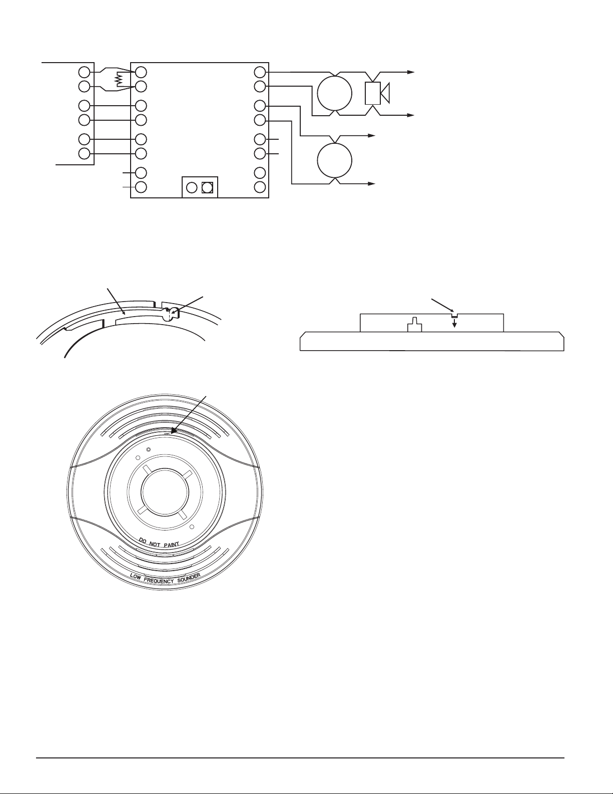
PLASTIC LEVER
BREAK TAB AT
DOTTED LINE BY
TWISTING TOWARD
CENTER OF BASE.
USE SMALL-BLADED
SCREWDRIVER TO
PUSH PLASTIC LEVER
IN DIRECTION OF
ARROW.
SLOT
C0144-00
C1082-01
FIGURE 7A. ACTIVATING THE TAMPER-RESIST FEATURE
FIGURE 7B. REMOVING THE DETECTOR HEAD FROM THE BASE
FIGURE 6. SYNCHRONIZATION DIAGRAM (FOR MDL SERIES SYNC MODULES ONLY)
C1090-02
NOTE: Wiring shown for System Sensor MDL Series Sync Module. For additional wiring configurations, see your sync module manual.
FACP #1
+
–
+
–
+
–
+
–
+
–
+
–
+
–
EOL
(1)
}
}
}
}
HORN
CONTROL
ZONE 1
IN
ZONE 2
IN
SLAVE
IN
+
–
+
–
+
–
+
–
}
}
}
}
ZONE 1
OUT
ZONE 2
OUT
NAC
SLAVE IN
SLAVE
OUT
TEMP JUMP OFF
NAC 1
}
B+
B–
NAC 2
}
B+
B–
NAC 3
}
B+
B–
TO NEXT DEVICE
OR EOL (1)
TO NEXT DEVICE
OR EOL (1)
2 CLASS B ZONES
MASTER
SOUNDER
BASE
SOUNDER
BASE
OPTIONAL
Triga™ is a trademark of TRIGA Life Safety Systems, LLC. System Sensor® is a registered trademark of Honeywell International, Inc.
4 I56-4151TRG-005
©2021. 4/22/2021
This manual suits for next models
1
Other TRIGA Marine Equipment manuals


