Trigon Electronics CastleGate III User manual

Page 1
CastleGate III
January 9, 2006
255 Glider Circle • Corona, CA 92880
(951) 371-1730• Facsimile (951) 371-2592
www.TrigonElectronics.com
CastleGate III
Single Resident No-Phone-Charge System
INSTALLATION
AND
OPERATION INSTRUCTIONS

Page 2
CastleGate III
TABLE OF CONTENTSTABLE OF CONTENTS
TABLE OF CONTENTSTABLE OF CONTENTS
TABLE OF CONTENTS
INTRODUCTION-------------------------------------------------------------------- . 3
PRODUCT OVERVIEW------------------------------------------------------------- 3
MOUNTING --------------------------------------------------------------------------- 4
Backbox Dimensions ----------------------------------------------------------------- 4
WIRING -------------------------------------------------------------------------------- 4
Wiring Diagram------------------------------------------------------------------------ 5
PROGRAMMING -------------------------------------------------------------------- 6
Getting into programming mode ------------------------------------------------- 6
Programming entry codes --------------------------------------------------------- 6
Deleting entry codes --------------------------------------------------------------- 6
Changing programming code ----------------------------------------------------- 6
Programming time-of-day clock ------------------------------------------------- 6
Programming relay 1 “on” time/day --------------------------------------------- 7
Programming relay 1 “off” time/day -------------------------------------------- 7
Programming relay 2 “on” time/day --------------------------------------------- 7
Programming relay 2 “off” time/day -------------------------------------------- 7
Setting relay 1 cycle time --------------------------------------------------------- 7
Setting relay 2 cycle time --------------------------------------------------------- 7
OPERATION--------------------------------------------------------------------------- 8
Calling the Resident --------------------------------------------------------------- 8
Call waiting ------------------------------------------------------------------------- 8
Receiving a Call form the Gate--------------------------------------------------- 9
Special Resident Operation ------------------------------------------------------- 9
Gate Control mode ----------------------------------------------------------------- 9
Trouble Shooting Guide ----------------------------------------------------------- 10

Page 3
CastleGate III
INTRODUCTIONINTRODUCTION
INTRODUCTIONINTRODUCTION
INTRODUCTION
This manual contains all the information required to
successfully install and program the TRIGON
CastleGate III. If you are using this manual to install
this unit, it is very important for you to read all sections
in order.
You should read these instructions before you begin this
installation. This will insure correct installation.
If you are using this manual as a programming guide
after the initial installation, you may find the TABLE
OF CONTENTS useful in locating the particular
programming procedure needed.
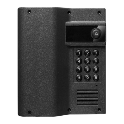
The CastleGate III is a “No Phone Charge”, handsfree
telephone entry system for use at a single residence. It
has two distict operating modes:
1. The primary mode is where the Castlegate III uses
the resident’s existing TELCO telephone line for
communication and access control. Since gate calls do
not go through the telephone company network, there
are no charges for calls made from the system. In this
mode the resident's standard single line telepone is used
for both TELCO calls as well as calls from the front
gate.
2. The secondary mode is where the Castlegate III does
not use the TELCO line, but is wired directly from the
gate to the residence. In this mode either a separate
telephone must be available or a two line telephone at
each resident phone line outlet.
Visitors initiate calls from the entrance by pressing the
“call” button on the illuminated faceplate. The call is
received in the residence. The resident can discern
between entrance calls and regular telephone calls due
to the unique ring modes available in the Castlegate III
programming.
With up to 50 codes available, residents, employees, or
guests can access the premises immediately by entering
their personnal entry code on the CastleGate III’s
keypad.
T
e
l
ep
h
one
Li
ne -
22
AWG
;
Shielded or Twisted,
2 Conductor
Camera, Door or Gate
Secondary
Relay
Postal
Lock
Box
Primary
Output
Relay
Main Entrance
Power Cabling -
Shielded or Twisted,
2 Conductor,
18AWG up to 250'
16AWG up to 500'
Dimensions
Telephone Line - 22 AWG;
Shielded or Twisted,
2 Conductor to residence
Surface Mount
Flush Mount
DESIGN
9"
11" 12"
14" 3.62"
3.62"
HEIGHT WIDTH DEPTH
Hookup Specifications
Dimensions:
Surface Mount: 8" x 5" x 3.5"
PRODUCT OVERVIEWPRODUCT OVERVIEW
PRODUCT OVERVIEWPRODUCT OVERVIEW
PRODUCT OVERVIEW

Page 4
CastleGate III
Figure 2
MOUNTINGMOUNTING
MOUNTINGMOUNTING
MOUNTING
UsetheappropriateBackbox drawing (Fig.2) toprepare
the surface on which the Trigon is to be mounted. The
unit is designed to be as weather-resistant as possible.
The sides of the front plate enter rain gutters when the
front face is closed.
For surface mount versions:For surface mount versions:
For surface mount versions:For surface mount versions:
For surface mount versions: Bolt the
backbox to the mounting surface using the four 5/16"
holes in the chassis. Also, pull the wiring through the
access hole in the rear of the backbox. At this point,
the wiring should NOT be live (energized).
For flush mount versions:For flush mount versions:
For flush mount versions:For flush mount versions:
For flush mount versions: Prepare
rectangular hole 8.25 inches by 5.25 inches by 3 inches
deep. Pull the wiring through the access hole in the
bottom of the backbox. At this point, the wiring should
NOT be live (energized).
WARNING:WARNING:
WARNING:WARNING:
WARNING:
If a conduit is to be attached to the bottom of the
Castlegate III, be certain the conduit connector does not
protrude more than 1/2" into the backbox. Any deeper
penetration will contact the circuit board when the face
plate is installed. If enough pressure is applied, the
circuit board will be bowed and may contact other
components causing erratic behavior.
1. Do not power any other device from the Trigon’s
12 VAC transformer.
2. Do not energize wires until installation is completed.
3. Ground the unit by attaching a separate 12 AWG
ground wire to the ground location on the terminal
block (see wiring diagram Fig. 3) . This ground wire
should go to a grounding rod or grounded metal
conduit.
4. Trigon recommends that an EMI filter (Cornell-
Dubilier ModelAPF 1021 or equivalent) be mounted
between the 12 VAC transformer output and the unit.
EMI/RFI filters are available from Trigon. Mount
the filter as close to the unit as possible. Ground the
filter to the same point as unit ground. If using
shielded cable, ground the shielding to the same point
as the unit and filter. To avoid ground loops, do not
ground the shield at both ends. Use 600V insulated
wire for this installation.
5. Use 22 AWG wire on Telco / Resident line run
distances of up to 2500 feet. Consult with the factory
for distances greater than 2500 feet. If a substitute
transformer is used, be sure it is rated 12 VAC, 20VA,
U.L class 2 listed. The 12 VAC input power wires
shouldbe 18AWG,600V, insulatedwire. This should
be sufficient for distances up to 200 feet.
6. Isolate the Telco phoneline in and the Resident
phoneline out, from the 12 VAC power wires. This
will prevent 60 Hz hum from occurring on the
phoneline.
7. Use the enclosed wiring diagram (Fig. 3) for wire
connection information. Be sure to hook up the
memory battery.
8. Relays 1 and 2 are dry contact Form C type, rated
for 5AMPS @ 30 VDC/ 250VAC. A 3-wire harness
is included to wire the relay outputs.
9. Energize unit. You should hear one beep followed
by four beeps if unit is new or if the battery was
disconnected during a power failure. The four beeps
mean the unit is initializing memory.
5.00"
4 Holes
.312" Dia
marked as 'K'.
2 Holes
.875" Dia.
(knock-out)
marked as 'J'
BOTTOM
BACK
Castlegate III Back & Bottom Plate
3.50
1.75
1.75
8.00"
3.75
3.50
1.05
2.10
2.50
J
J
KK
KK
WIRINGWIRING
WIRINGWIRING
WIRING

Page 5
CastleGate III
Figure 3
Wiring DiagramWiring Diagram
Wiring DiagramWiring Diagram
Wiring Diagram
Telephone Line
22AWG
Shielded or Twisted
2-Conductor
Up to 2500 ft
Telco In
GRND
Residence
Out
Battery
Back-up +-
Postal Lock
Input
Power Cabling
18AWG up to 250'
16AWG up to 500'
Shielded or Twisted
2-Conductor
12VAC
Rela y
2
Rela y
1
Audio
Volume
NC ( n ormally closed)
NO (normally open)
C (common)
NC (normally closed)
NO (normally open)
C (common)

Page 6
CastleGate III
PROGRAMMINGPROGRAMMING
PROGRAMMINGPROGRAMMING
PROGRAMMING
Getting into programming mode:Getting into programming mode:
Getting into programming mode:Getting into programming mode:
Getting into programming mode:
A. Programming at the unitA. Programming at the unit
A. Programming at the unitA. Programming at the unit
A. Programming at the unit
Press the ' * ' key followed by the Program Code (5269
if the unit is new). You will hear two 'beeps' indicating
Program Code accepted.
NOTE:NOTE:
NOTE:NOTE:
NOTE: If the secondary mode (no TELCO line) is
warranted, the program code must be changedAT THE
UNIT to a number between 0000 and 4999 before
programming from the residence can be accomplished.
See Changing Program Code.
B. Programming from the houseB. Programming from the house
B. Programming from the houseB. Programming from the house
B. Programming from the house
Lift your telephone's receiver and press 52*. You will
hearthree 'beeps'indicating GateControl Codeaccepted.
Next press the ' * ' key followed by the Program Code
(5269 if the unit is new). You will hear two 'beeps'
indicating Program Code accepted.
Note: When calling the gate, if the CastleGate III fails
to answer by pressing 52 * (or the new program access
code you've set), press 00 * to access it. If you find you
must frequently use 00 * to access your CastleGate III
settings, please contact your installing dealer and ask
him to contact the factory.
C. Programming Entry Codes:C. Programming Entry Codes:
C. Programming Entry Codes:C. Programming Entry Codes:
C. Programming Entry Codes:
Entry codes make it possible for the user to enter a code
at the unit and gain access. To program entry codes, the
unit must be in programming mode first.
Press “* 1”. You will hear one beep.
Enter the new 4-digit entry code. You will hear two
'beeps' (four 'beeps' indicate memory full).
Code numbers beginning with 1-4 will operate relay #1.
Code numbers beginning with 5-9 will operate relay #2.
Numbersbeginning with 0will operate bothrelays. You
willhear twobeeps. If youhear fourbeeps here,memory
is full (see deleting entry codes).
If you have multiple entry codes to input, simply enter
the “* 1” again and the second new code. Do this in
like fashion until you are finished.
To exit the programming mode, press “* *”.
D. Deleting Enry Codes:D. Deleting Enry Codes:
D. Deleting Enry Codes:D. Deleting Enry Codes:
D. Deleting Enry Codes:
Unit must be in programming mode.
Enter “* 4”. You will hear one beep.
Enter the 4 digit entry code that you want to delete. You
will hear two beeps. Erasure is complete. If you hear
fourbeeps here, thecode entered wasnot in the memory.
Repeat until all desired Entry Codes have been erased
To exit programming mode, enter “* *”.
Reconnect battery and restore power to the unit. The
unit should beep once, and then four more times. The
memory is now erased and the programming code is set
back to 5269.
F. Programming time of day clock:F. Programming time of day clock:
F. Programming time of day clock:F. Programming time of day clock:
F. Programming time of day clock:
The time of day clock allows automatic operation of
relays 1 and 2. The unit must be in programming mode
to set the internal clock.
First, enter “* 6”. You will hear one beep.
Next, enter the hour. (military time; 00 - 23). To
convert to military time, add 12 to the hour
if in the P.M. For example, 3 P.M. = 15; 2
A.M. = 02.
Next, enter the minutes. (00-59)
Lastly, enter the day of week. (01-07 is Mon.-
Sun.) After completing this step you should
hear two beeps.
Note:Note:
Note:Note:
Note: If, while performing this step, you lose the
ability to access the programming mode, disconnect
power from the unit. Disconnect the battery terminal
on the circuit board for one minute (see wiring diagram
in appendix).
E. Changing the Program code,E. Changing the Program code,
E. Changing the Program code,E. Changing the Program code,
E. Changing the Program code,
Operating mode, Ring cadence:Operating mode, Ring cadence:
Operating mode, Ring cadence:Operating mode, Ring cadence:
Operating mode, Ring cadence:
This feature allows the user to change the programming
code to something other than the factory preset of 5269
which also sets the operating mode and ring cadence.
Note:Note:
Note:Note:
Note: 1. Normal mode with a TELCO line, program
code should be set greater than 5000 and less than 9999
2. Intercom mode with no TELCO line, program code
should be set greater than 0000 and less than 4999.
3. Ring cadence is 1-on, 1-off, 1-on, 3-off (seconds) if
program code is set to an odd number.
4. Ring cadence is 2-on, 4-off (seconds) if program
code is set to an even number.
The unit must be in programming mode. Enter “* 5”.
You will hear one beep.
Enter the new 4-digit programming code. You will hear
two beeps. Keep in mind that the 5269 code (or any
other previous code) is no longer valid. Keep good,
safe record of your new programming code for future
use.
Note:Note:
Note:Note:
Note: Gate Control Mode is achieved by using the
first 2 digits of the program code. If the program code
is changed to “1234” then Gate Control Mode is
achieved by tone dialing “12*” from inside the house.
To exit programming mode, enter “* *”.

Page 7
CastleGate III
PROGRAMMING cont.PROGRAMMING cont.
PROGRAMMING cont.PROGRAMMING cont.
PROGRAMMING cont.
I. Programming Relay 2 “on” time:I. Programming Relay 2 “on” time:
I. Programming Relay 2 “on” time:I. Programming Relay 2 “on” time:
I. Programming Relay 2 “on” time:
This feature allows time clock control of Relay 2.
You may set the relay to activate at a certain time of
day and deactivate at a later time. (NOTE: To program
relay 2, do the following:
Enter “* 9”. You will hear one beep.
EnterStart time. (militaryformat; hours:minutes,
i.e. “0630” , “1545”). Entry must be four
digits.
Enter Begin-End Days. (01-07 is Mon. through
Sun.). Aftercompleting thisstep, youshould
hear two beeps.
To exit the programming mode, press “* *”.
K. Setting relay 1 cycle time:K. Setting relay 1 cycle time:
K. Setting relay 1 cycle time:K. Setting relay 1 cycle time:
K. Setting relay 1 cycle time:
Cycle time is the duration of time the relay remains
energized.
Relay 1 cycle time may be programmed to be from 00 to
99 seconds.
Enter “* 2” You will hear one beep.
Enter gate time This is a two-digit number (00-
99) that represents a time value from 00 to
99 seconds. After completing this step, you
will hear two beeps.
L. Setting relay 2 cycle time:L. Setting relay 2 cycle time:
L. Setting relay 2 cycle time:L. Setting relay 2 cycle time:
L. Setting relay 2 cycle time:
Relay 2 cycle time may be programmed to be from 0
to 99 seconds.
Enter “* 3” You will hear one beep.
Enter gate time This is a two-digit number (00-
99) that represents a time value from 00 to
99 seconds. After completing this step, you
will hear two beeps.
Note:Note:
Note:Note:
Note:Using 00 for a relay cycle time will disable that
cycle timer.
Note:Note:
Note:Note:
Note: Using 01 for a relay cycle timer will only
guarantee cycle period ranging from 0 to 1 second and
may not produce an acceptable pulse. Use 02 seconds if
a short pulse is the desired objective.
G. Programming Relay 1 “on” time:G. Programming Relay 1 “on” time:
G. Programming Relay 1 “on” time:G. Programming Relay 1 “on” time:
G. Programming Relay 1 “on” time:
This feature allows time clock control of Relay 1. You
may set the relay to activate at a certain time of day and
deactivate at a later time. (NOTE: To program relay 1,
do the following:
Unit must be in programming mode.
Enter “* 7”. You will hear one beep.
EnterStart time. (militaryformat; hours:minutes,
i.e. “0630” , “1545”). Entry must be four
digits.
Enter Begin-End Days. (01-07 is Mon. through
Sun.). Aftercompleting thisstep, youshould
hear two beeps.
To exit the programming mode, press “* *”.
Example: “*7 (beep) 06 30 15 (beep,beep)”This
example would set relay 1 on at 6:30 AM Monday
through Friday.
H. Programming Relay 1 “off” time:H. Programming Relay 1 “off” time:
H. Programming Relay 1 “off” time:H. Programming Relay 1 “off” time:
H. Programming Relay 1 “off” time:
Enter “* 8”. You will hear one beep.
Enter end time: (military format; hours:minutes,
i.e.“0630” , “1545”). Entry must be4 digits.
Enter Begin-End days: (01-07 is Mon. through
Sun.). After completing this step, you
should hear two beeps.
To exit the programming mode, press “* *”.
J. Programming Relay 2 “off” time:J. Programming Relay 2 “off” time:
J. Programming Relay 2 “off” time:J. Programming Relay 2 “off” time:
J. Programming Relay 2 “off” time:
Unit must be in programming mode.
Enter “* 0” You will hear one beep.
Enter end time: (military format; hours:minutes,
i.e. “0630” , “1545”). Entry must be 4 digits.
Enter Begin-End days: (01-07 is Mon. through
Sun.). After completing this step, you should
hear two beeps.
To exit the programming mode, press “* *”.

Page 8
CastleGate III
OPERATIONOPERATION
OPERATIONOPERATION
OPERATION
A. Calling the Resident:A. Calling the Resident:
A. Calling the Resident:A. Calling the Resident:
A. Calling the Resident:
A visitor simply presses the “call” button on the front of
the CastleGate III to alert the resident to their presence.
Theunit thenautomatically ringsthe resident'stelephone.
When the call is received, the resident my grant entry by
dialing “6” or “9” on their telephone. To deny entry, the
resident simply hangs-up their telephone handset.
Residents may let themselves in by using a
programmable 4-digit “keyless” entry code. Up to 50
such codes may be programmed into the CastleGate II.
To avoid issuing keys, codes may be given to gardeners,
pool maintenance personnel, and such. All codes can be
easily voided.
Residents will know when a visitor is requesting entry,
even if they are using their telephone at the time. Atone
will notify them of an incoming call. They then press
the “#” key on their telephone to put the outside call on
hold. When the visitor at the gate has been granted or
denied access, the resident can return to their outside
call by again pressing the “#” key on their telephone.
B. Call waiting:B. Call waiting:
B. Call waiting:B. Call waiting:
B. Call waiting:
In the case where you are using your telephone when a
call is initiated at the gate, you will hear a short tone in
your handset every 3 seconds. To see who is at the gate
without interrupting your call, press a ‘#” tone from a
touchtone telephone. The person on the telephone with
you will automatically be put on hold and you will be
transferred to the visitor at the gate. After handling the
gate call, you may switch back to your previous
telephone conversation by pressing “0” or “#”. If you
hangup while someone is on hold or during an incoming
call, the CastleGate II will alert you by ringing your
telephone approximately 3 seconds later.
If you are talking to a visitor at the gate and you receive
an incoming telephone call, you will hear a clicking
sound in your handset. After handling the gate call,
press the hookswitch momentarily to answer incoming
telephone call.
Note:Note:
Note:Note:
Note: The following devices are connected to:
Relay #1 _____________________________________
Relay #2 _____________________________________
Note:Note:
Note:Note:
Note: Your Program
Access Code Is: _________________________

Page 9
CastleGate III
OPERATION cont.OPERATION cont.
OPERATION cont.OPERATION cont.
OPERATION cont.
Figure 4
12
ABC
3
DEF
4
GHI
5
JKL
6
MNO
7
PRS
8
TUV
9
WXY
*0#
Operate Relay #1
for cycle time
Operate Relay #2
for cycle time
Disconnect from gate
and switch to Call Waitin
g
Disconnect from gate
and connect to telephone
company dial tone
D.D.
D.D.
D.
Gate Control Mode:Gate Control Mode:
Gate Control Mode:Gate Control Mode:
Gate Control Mode:
You may control the Castlegate III from inside your
house. Lift your telephone’s receiver.
Dial the first 2 digits of your program access code,
followed by the “*”.
You will hear 3 beeps and be able to hear any activity
near your gate.
C. Receiving a Call from the Gate:C. Receiving a Call from the Gate:
C. Receiving a Call from the Gate:C. Receiving a Call from the Gate:
C. Receiving a Call from the Gate:
Answer telephone and identify visitor. Using your
touchtone or rotary telephone keypad (Fig.4) , you have
the following choices:
Press "6" to open door/gate attached to relay #1(close
relay #1 for relay cycle time).
Press "9" to activate device attached to relay #2 (close
relay #2 for relay cycle time).
"Hang up" to disconnect from gate call.
Press "#" to disconnect from gate and switch to Call
Waiting.
Note:Note:
Note:Note:
Note: Press " 0" to disconnect from the gate and to
obtain telephone company dial tone.
12
ABC
3
DEF
4
GHI
5
JKL
6
MNO
7
PRS
8
TUV
9
WXY
*0#
Latch & Hold Relay #1
(
To release press #5 and
h
ang up)
L
atch Relay #1
(
Released when resident's
t
elephone is hung up)
L
atch & Hold Relay #2
(
To release press #8 and
h
ang up)
Latch Relay #2
(Released when resident's
telephone is hung up)
Figure 5
Next use any of the tone commands below to control
the system. Two beeps will acknowledge your choice
tolatch a relay. Asingle beep isthe responce toa release
command.
Response to tones 6 and/or 9, will be a series of beeps
until cycle times are completed.
E. Special Resident Operation:E. Special Resident Operation:
E. Special Resident Operation:E. Special Resident Operation:
E. Special Resident Operation:
Press "4" to latch open door or gate connected to relay
#1.
Sends a continuous “open" command to the relay. Must
be released by sending a"close" command. (see
following)
Press "5" then hang up to release/close door or gate
connected to relay #1 (Releases device only after
telephone is hung up).
Press "7" to activate/latch device connected to relay
#2.
Sends a continuous “open" command to the gate. Must
be released by sending a "close" command. (see
following)
Press "8" then hang up to deactivate/release device
connected to relay #2 (Releases device only after
telephone is hung up).
(Note)(Note)
(Note)(Note)
(Note)
You may press "5" to latch open the door or gate
connected to relay #1, for the duration of the call. The
door/gate will automatically close when the telephone
is hung up.
You may press "8" to latch the secondary device
connected to relay #2.,for the duration of the call. The
secondarydevice willbe deactivatedwhen thetelephone
is hung up.

Page 10
CastleGate III
TROUBLE SHOOTING GUIDETROUBLE SHOOTING GUIDE
TROUBLE SHOOTING GUIDETROUBLE SHOOTING GUIDE
TROUBLE SHOOTING GUIDE
NO DIAL TONENO DIAL TONE
NO DIAL TONENO DIAL TONE
NO DIAL TONE
1. Check input power at unit. Should be 12
VAC. Check fuse.
2. Check that unit is properly grounded to a
good Earth ground.
3. Current starved. Increase AC input wire
size.
4. Remove power, wait 5 seconds, restore
power. Check for dial tone.
5. Check for phone line. Should be 48-52
VDC across phone line terminals (on
hook).
6. Check VOLUME adjustment on PC board.
7. Check “SPKR” plug on PC board. Make
sure speaker is properly plugged in
(Handsfree units).
8. Verify that contacts and wires are clean and
tight.
CANNOT PROGRAMCANNOT PROGRAM
CANNOT PROGRAMCANNOT PROGRAM
CANNOT PROGRAM
1. Incorrect/lost program code.
2. Not entering “*” before program code.
3. Try ‘NO DIAL TONE’troubleshooting
procedures.
4. Keypad damaged. Check for vandalism.
5. Check that Program Prom/Microprocessor
is fully seated.
LOSES MEMORYLOSES MEMORY
LOSES MEMORYLOSES MEMORY
LOSES MEMORY
1. Electrical noise on power line. Install
EMI/RFI filter.
2. Excessive electrical noise from strike.
Use low current strike.
3. Unit transformer shared with another
device (i.e. door strike).
TENANT CANNOT ACTIVATETENANT CANNOT ACTIVATE
TENANT CANNOT ACTIVATETENANT CANNOT ACTIVATE
TENANT CANNOT ACTIVATE
STRIKE/GATESTRIKE/GATE
STRIKE/GATESTRIKE/GATE
STRIKE/GATE
1. Tenant not pressing correct number on
phone.
2. Strike/gate operator not wired correctly.
3. Missing or incorrect power to strike or gate
operator.
4. Current starved. Increase wire size.
5. Tone may be too brief in duration (cordless
phones, etc.).
AC HUM IN EARPIECE/AC HUM IN EARPIECE/
AC HUM IN EARPIECE/AC HUM IN EARPIECE/
AC HUM IN EARPIECE/
SPEAKERSPEAKER
SPEAKERSPEAKER
SPEAKER
1. Phone wires running in same conduit as AC
power.
2. Unit not properly grounded.
3. Defective microphone.
TENANT CANNOT HEARTENANT CANNOT HEAR
TENANT CANNOT HEARTENANT CANNOT HEAR
TENANT CANNOT HEAR
VISITORVISITOR
VISITORVISITOR
VISITOR
1. Defective handset/microphone.
2 Too much background or street noise.
Relocate unit.
Feel Free to call our Techical Suppport:
(800) 842-7444 or (951) 371-1730
www.TrigonElectronics.com
Table of contents
Other Trigon Electronics Intercom System manuals
Trigon Electronics
Trigon Electronics Minipak User manual
Trigon Electronics
Trigon Electronics 02A00311 Quick start guide
Trigon Electronics
Trigon Electronics MiniGuard IID Technical specifications

Trigon Electronics
Trigon Electronics MiniGuard IID Operating instructions
Trigon Electronics
Trigon Electronics Minipak User manual

Trigon Electronics
Trigon Electronics Miniguard HF-2 Series Quick start guide
Trigon Electronics
Trigon Electronics MiniGuard IID Series Technical specifications
Trigon Electronics
Trigon Electronics T.A.C. 500 User manual


