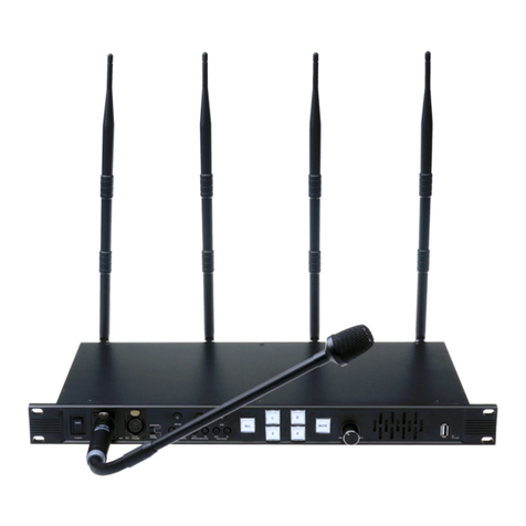
ProX XW-IS4 User manual

XW-IS4
XW-IS4
Intercom SystemIntercom System

Table of Contents
1. IMPORTANT INFORMATION .............................. 1
2. SAFETY PRECAUTIONS .................................... 1
3. STATEMENT ....................................................... 2
4. OVERVIEW ......................................................... 3-5
5. OPERATION ........................................................ 6-9
6. TROUBLE SHOOTING ........................................ 10
7. PACKING CONTENT ........................................... 11

Important Information
Read this user’s manual carefully before use and retain for future reference.
The XW-IS4 warranty may NOT apply to below cases:
■ Repairs or product modification and alterations executed by unauthorized service personnel.
■ When damages caused by accidents include but not limited to lightning, water or fire.
■ The power input voltage used is not in the specified range (100-260V AC, 10-20V DC).
■ The serial number on the product has been altered, deleted, removed or made illegible.
Safety Precautions
TO AVOID RISK OF ELECTRICAL
SHOCK, DO NOT ATTEMPT TO
OPEN THE UNIT BY YOURSELF.
FOR ANY ASSIST,
PLEASE CONTACT YOUR LOCAL
DISTRIBUTOR OR PRO-X.
■ Turn off the power switch before connecting the unit with other equipment.
■ Before using an external power supply, always check that the voltage is within the
specified range and that the polarities of the connector are correct.
■ Do not use the unit in high moisture environment, which may cause electric shock
or fire. Turn off the power switch if any liquid gets inside it.
■ Do not place the unit on an uneven surface, which may cause the unit fall.
■ When the unit is left unused for a long period of time, disconnect it from power
source, and take the batteries out from IS-HS/IS-BP. Always disconnect the power
cord from power outlet when not using. This reduces the risk of electric shock or fire.
■ Do not use the unit near any heat sources such as radiators, heat registers,
stoves, or other devices (including amplifiers) that produce heat.
■ Clean the unit only with dry cloth.
WARNING
RISK OF
ELECTRICAL
SHOCK
DO NOT OPEN
1

Statements
Operations in following conditions may cause faults on wireless intercom.
● With thick walls or obstacles between Base Station and IS-HS/IS-BP;
● Close to large-scale metal objects such as a truck or being set on a metal shelf;
● With large transformer or high voltage electrical substation nearby;
● Around airport or other high precision instruments;
● With high-power wireless communication equipment nearby;
● With other devices working under the similar frequency nearby;
Introduction
XW-IS4 is a Full-Duplex wireless Intercom system. It's designed for operation of live
show, program production, broadcast, and other applications where wireless
communication is required. It features advanced digital wireless and Audio Codec
technology to allow the director, camerapeople and control room communicate with
each other freely without cables.
● Full-Duplex Intercom;
● Wireless intercom working distance up to 250m;
● 4 channels available, IS-HS or IS-BP can be selected for each channel;
● Real-time Tally support;
2

Front Panel of Base Station
Back Panel of Base Station
3
SPEAKER
POWER MIC VOX
2W/4W VOX AUX
VOL
MIN MAX
ININ
INTERCOM LEVEL AUX LEVEL
OUT OUT
LEVELLEVEL
5V
DC OUT
HEAD
PHONE ALL
1 2
34
MUTE
MIC
Power Switch
XLR Socket for
Microphone Input
(1st Audio Input)
HEADPHONE/SPEAKER
Selector Switch
2-Wire/4-Wire
Selector Button
Voice Control
Enable Button
Auxiliary Audio
Enable Button
Volume Control of
Microphone Input
Voice Control Enable
Electrical Level Adjustor
Volume Control of
Intercom Output/Input
Volume Control of Auxiliary
Audio Output/Input
Enable Button of All Channels
Enable Button and
Status Indicator of
IS-HS1 to IS-HS4/
IS-BP1 to IS-BP4
Mute Button for
All Channels
Volume Control of
Headphone/Speaker
from Minimum to Maximum
Built-in Speaker
5V DC Output
VHVH
2 WIRE
INPUTOUTPUT
AUX AUDIO INTERCOM
Red LED
GNDCH
1 2 3 4 1 2 3 4 NC NC
Green LED
TALLY
MODE
H
L
FREQ
1.8G
1.9G
Red LED
GNDCH
1 2 3 4 1 2 3 4 NC NC
Green LED
AC Input
DC Input
Tally Active-high and
Active-low DIP Switch
When the lever is at upper
location, Tally signal is in
active-high. When the
lever is at bottom location,
Tally signal is in active-low.
1.8G/1.9G Frequency Points Selector DIP Switch
Tally Input
4-Wire Intercom Port
(RJ11 and XLR-4F parallel inside)
Pin1, Pin4: Balanced Audio Input;
Pin2, Pin3: Balanced Audio Output
XLR -4F R J11
2-Wire Intercom Port
(XLR-3F and XLR-3M parallel inside)
Pin1: Public; Pin2: Null; Pin3: Audio
XLR -3M X LR- 3F
Auxiliary Audio Input/Output
Pin1: Public; Pin2: Audio”+”;
Pin3: Audio”-”
Antenna Connectors
XLR Socket
for Headphone
(2nd Audio
Input/Output)

Control Panel of Wireless Headset (IS-HS)
Indicator of Working Status
1.9G/1.8G Frequency
Points Selector DIP Switch
MIC-Enable Button in Half Duplex
IS-HS Calls Base Station /
IS-HS Registers on Base Station
TALLY Light Jack
Volume Control Dial
Power Switch
Power LED
Battery Box (AAA Battery×3)
Earphone Jack
4

Control Panel of Belt Pack (IS-BP)
CALL
ON
OFF
1.8G 1.9G
Volume Control Knob
MIC-Enable Button in Half Duplex
LCD
Tally LED
Tally Output
Headphone Jack
Battery Box (AA Battery×3)
or Nokia BL-5C Lithium-ion Battery
1.9G/1.8G Frequency
Points Selector Switch
Belt Pack Calls Base Station /
Belt Pack Registers on Base Station
Power Switch
Antenna
5

Operation
Installation
1.Check to be sure that frequency points are same selected on both IS-HS/IS-BP and Base Station.
2.Screw antennas on the back panel of Base Station.
3.Apply AC power to Base Station via AC power cord or power Base Station with a 10-20V
DC power supply.
4.Turn on the power switch of Base Station, red power LED lights up. Base Station is in
Half Duplex by default.
Remarks: Use extension cord and antenna installation board to arrange antennas at a
preferred place. There are one small end and one large end on extension cords. Screw
small ends on the antenna connectors of back panel of Base Station, and screw
antennas on the large ends. The large ends can be arranged on antenna installation
board with magnetic force. There’s one screw hole on antenna installation board, which
makes it easy to be installed on your equipment stand.
Full Duplex
Half Duplex
IS-HS/ IS-BP
Calls Base Station
Mute Mode
Registered,
Base Station powered
off,IS-HS/IS-BP
powered on
Unregistered,
IS-HS/IS-BP
Powered on
Remarks:Flash quickly: 200ms “ON”, 200ms “OFF”
Flash slowly: 500ms “ON”, 500ms “OFF”
Flash: 3s “OFF”, 1s “ON
Base Station
status indicator
flashes
“CHx” status indicator
stays on
status indicator
flashes quickly
“MUTE” LED stays on
IS-HS
“SYS” LED stays on
“SYS” LED stays on
“SYS” LED flashes
quickly
“SYS” LED stays on
“SYS” LED flashes
“SYS” LED flashes
quickly for 5s and then
stays off. Any button
pressed, “SYS” LED
flashes quickly for 5s
again.
IS-BP
LCD displays
“Full Duplex”
LCD displays
“Half Duplex”
LCD displays “Call”
LCD displays “Mute”
LCD displays
“Searching”
LCD displays
“Unregistered”
Unit
Working Status
/
/
LED and LCD Indications
6
“CHX”
“CHX”

Base Station
1.Logout/Registration Mode
Press “MUTE” button and turn on the power switch in the same time, keep “MUTE”
button pressed till 4 Channel status indicators flash quickly (200ms “ON”, 200ms
“OFF”). Release “MUTE” button, Base Station is in Logout/Registration mode.
2.Logout
In Logout/Registration Mode, the channel keeps previous registration information if its
status indicator is on. This channel needs to be logged out before it is registered again.
To log out all channels, press “ALL” button. Logout can only be done on Base Station.
3.Registration
In Logout/Registration Mode, the status indicators of unregistered channels stay
off. The registration operation needs to be done from CH1 to CH4 orderly.
Press “CHx” button of unregistered channels, the “CHx” status indicator flashes
slowly (500ms “ON”, 500ms “OFF”).
•For IS-HS, press and hold “CALL” button on an unregistered IS-HS and turn on the
power switch in the same time. Keep “CALL” button pressed until “SYS” LED flashes
slowly. This IS-HS is registering on Base Station.
•For IS-BP, press and hold “Call” button on an unregistered IS-BP and turn on the
power switch in the same time. Keep “Call” button pressed until LCD displays
“Registering”. This IS-BP is registering on Base Station.
When the registration is completed, the corresponding Base Station “CHx” status
indicator stays on, IS-HS “SYS” LED stays on, IS-BP LCD displays “Registered”.
Remark: If the registration is failed, try the above steps again.
4.Exit from Logout/Registration Mode
Turn off the power switch of Base Station after registration. The set is ready to work
when Base Station is turned on again.
Remarks:
1.When registration is completed between Base Station and IS-HS/IS-BP, they can't
be used for communicating before they are exited from Logout/Registration Mode.
2.After Base Station is powered off and on, the registered IS-HS/IS-BP will be
connected to Base Station automatically in Half Duplex (The connection is well
functioning with Base Station “CHx” status indicator and IS-HS “SYS” LED both
staying on, and IS-BP LCD displays “Connected”).
7

Volume Control of Headphone/Speaker
There are a 3-pin MIC socket and built-in speaker (1st Audio input/output) and a 4-pin
Headphone socket (2nd Audio input/output) on Base Station. Volume level of MIC can
be adjusted via “MIC LEVEL” dial. Volume level of Headphone and Speaker can be
adjusted via “VOL” knob. It's easy to select the way of communicating with IS-HS/ IS-
BP via “SPEAKER/HEADPHONE” selector switch.
Voice Control Enable Function (VOX)
1. Press “VOX” button on Base Station to activate voice control enable function, and
“VOX” LED stays on. When detected electrical level of Base Station Microphone is
over designed limitation, Audio channel of “MIC” input will be available and “MUTE”
LED will be off; if there’s no detected electrical level or the detected electrical level is
below the designed limitation for more than 10s, Audio channel of “MIC” input will be
disabled and “MUTE” LED will be on.
2. Press “VOX” button on Base Station to disable voice-enable function, and “VOX”
LED will be off; the control circuit of Base Station will turn off voice-enable function.
Intercom Operation & Indications
2-Wire, 4-Wire Intercom Operation and indications
1) 4-Wire is on by default when Base Station is turned on. Press “2W/4W” button to
enable 2-Wire Audio channel (including Audio input/output), and 4-Wire Audio
channel will be shut off. Base Station communicates with other equipments in Full
Duplex. Any active channel is included in intercom.
Connector: 3-pin XLR Male and Female paralleled inside
Audio Electrical Level: 1Vpp
2) When 2-Wire is on, Press “2W/4W” button to enable 4-Wire Audio channel
(including Audio input/output), and 2-Wire Audio channel will be shut off. Base
Station communicates with other equipments in Full Duplex. Any active channel is
included in intercom.
Connector: 4-pin XLR Female and RJ11 paralleled inside
Audio Level: 1Vpp
Communication between Base Station and IS-HS/IS-BP
1.Base Station communicates with all IS-HSs in Full Duplex
When Base Station quits all IS-HS/IS-BP from intercom, or Base Station is just
powered on and is in Half Duplex, press “ALL” button to include all registered IS-
HS/IS-BP communicating in Full Duplex. Status indicators for active channels flash
(3s “OFF”, 1s “ON”). Corresponding IS-HS “SYS” LED stays on, IS-BP LCD displays
“Full Duplex”.
8

When the set works in Full Duplex, press “ALL” button to quit all IS-HS/IS-BP from
intercom and the set works in Half Duplex. Base Station “CHx” status indicator stays
on, IS-HS “SYS” LED stays on, IS-BP LCD displays “Half Duplex”.
3.Base Station communicates with selected IS-HS/IS-BP in Half Duplex
When the set works in Full Duplex, press and hold Base Station “CHx” button for 3s,
IS-HS/IS-BP of the corresponding channel will be communicating with Base Station
in Half Duplex. Base Station “CHx” status indicator flashes slowly (500ms ON,
500ms OFF), IS-HS “SYS” LED stays on, IS-BP LCD displays “Half Duplex”.
Mute Mode on Base Station
When Base Station is in intercom with Headsets, press “MUTE” button and “MUTE”
LED will be on. All IS-HS/IS-BP and 4-Wire/2-Wire “AUX” output cannot hear sound
from Base Station. Re-press “MUTE” button to cancel Mute mode, “MUTE” LED will
be off.
IS-HS/IS-BP Calls Base Station
When Base Station “MUTE” LED is on or “CHx” button has been pressed to make
selected channel mute, cameraperson is able to press IS-HS “CALL” button/IS-BP
“Call” button to call Base Station. Base Station “CHx” status indicator will flash
quickly (200ms ON, 200ms OFF), IS-HS “SYS” LED will flash quickly (200ms ON,
200ms OFF), IS-BP LCD will display “Call”. Press Base Station corresponding
“CHx” button to allow the IS-HS/IS-BP come into Full-Duplex intercom.
Remarks: 1. When a IS-HS/IS-BP is mute by pressing corresponding “CHx” button
on Base Station, the IS-HS/IS-BP can't intercom with Base Station or other IS-
HS/IS-BP by pressing IS-HS “MIC” button or IS-BP “Talk” button, unless it calls Base
Station to enable the intercom channel first.
2. “CHx” status indicator flashes quickly before stays on, IS-HS “SYS” LED flashes
quickly before stays on, IS-BP LCD displays “Call” before showing “Half Duplex”
again.
IS-HS/IS-BP Communicates with Base Station in Half Duplex
When Base Station is just turned on or all IS-HS/IS-BP work in Half Duplex, press
and hold a IS-HS “MIC” button/ IS-BP “Talk” button, it can be included in Full Duplex
intercom temporarily. Base Station “CHx” status indicator flashes (3s OFF, 1s ON);
release “MIC” button, the set gets back to work in Half Duplex.
2.Base Station communicates with all IS-HS/IS-BP in Half Duplex
9

Auxiliary Audio Input
Press Base Station “AUX” button, the auxiliary audio input channel is enabled and
“AUX” LED lights up. Press the button again, the auxiliary audio input channel will
be disabled and “AUX” LED will be off.
When “AUX” is on, Audio connected with this port will be input to the system. The
Headphone or Speaker of Base Station outputs sound according to the position of
“HEADPHONE/SPEAKER” selector switch. If any channel from CH1-CH4 is active,
the corresponding IS-HS/IS-BP can hear sound too.
The auxiliary input signal electrical level can be adjusted via Auxiliary Level IN dial
of Base Station.
Audio Electrical Level: 1Vpp
Auxiliary Audio Output
When any channel is active, Audio signals collected in Base Station output from this
Auxiliary port.
The Auxiliary output signal electrical level can be adjusted via Auxiliary Level OUT
dial of Base Station.
Audio Electrical Level: 1Vpp
IS-HS/IS-BP
Registration
Refer to “Log out/Registration” of Base Station
Under-voltage Alarm
When the battery voltage is under-voltage, IS-HS “SYS” LED flashes every 10s
(200ms ON-200ms OFF-200ms ON), and IS-HS triggers low voltage alarm until
power is off. IS-BP LCD displays “Low Battery”.
Out of Distance Alarm
When IS-HS/IS-BP is working out of distance from Base Station, it triggers alarm of
“Ticking…Ticking…Ticking…” from earphone as a reminding.
10

Troubleshooting
1.Check if antennas of Base Station are loose or broken
and be sure they are installed in the right way
2.Check if the battery power of IS-HS/IS-BP is exhausted
3.Check if the working distance between Base Station and
IS-HS/IS-BP is within 250m LOS, if so, shorten the
distance and try again
4.Check if there is any high voltage or high power equipment
or high intensity magnetic field nearby
5.Check if there are obstacles, large metal objects between
Base Station and IS-HS/IS-BP
6.Try to restart the set
7.Try another frequency point and restart the set
Solutions
1.Make sure AC power cord is well inserted in a functional
power outlet
2.Check if the fuse under AC IN is broken
1.Check if the power switch is on
2.Check if installation of IS-HS/IS-BP batteries is right
3.Check if batteries are exhausted
1.Check if Tally indicator plug is inserted in the socket well
and steady
2.If the set works with a Switcher, check if the connection
of cables is correct
1.Check if IS-HS/IS-BP is registered on Base Station
2.Check if the set work on the same frequency point
3.Check if the battery power of IS-HS/IS-BP is exhausted
4.Be sure the volume of IS-HS/IS-BP is not at minimum
5.5.Check if HEADPHONE/SPEAKER selector switch is
in the right position
6.Check If working distance is more than 250m LOS,
if so,shorten the distance and try again
Fault
Base Station cannot be
turned on
The working distance
being less than 250m
or communication quality
being bad
Malfunction of connecting
or intercom
IS-HS/IS-BP can't get Tally
signal from Base Station
“SYS” LED stays off after
IS-HS/IS-BP is turned on
11

Standard Packing
Please check whether the following items are present in the package.
If not, please contact your dealer.
4 selectable units of
IS-HS /IS-BP in total
Item
XW-IS4 Base Station
Headphone
IS-HS (XW-IS-HS)
IS-BP (XW-IS-BP)
BL-5C Lithium Battery
USB Charger
MICRO USB Cable
Antenna (Base Station)
Gooseneck Microphone
Extension Cord for Antenna (1.5m)
AC Power Cord
AC-SMAM-SMAF Extension Cord (5m)
BaseStation Back Panel
Antenna Installation Board
User’s Manual
3.5*11P Connector
No.
1
2
3
4
5
6
7
8
9
10
11
12
13
14
Quantity
1
1
4
1 Set
4
1
4
1
1
4
1
1
1
Remarks
/
/
/
/
/
/
/
Optional
Optional
/
/
One set for each IS-BP
XW-IS4 Base Station
AC Power Cord
IS-HS
IS-BP
USB Charger Micro USB Cable
12
Extension Cord for
Antenna (1.5m)
3.5*11P Connector
Antenna
Gooseneck Microphone BaseStation Back Panel AC-SMAM-SMAF
Extension Cord (5m)
Headphone
Antenna Installation Board


Other manuals for XW-IS4
1
Table of contents
Other ProX Intercom System manuals
Popular Intercom System manuals by other brands
2N
2N Helios user manual

urmet domus
urmet domus AIKO 1716/1 quick start guide

urmet domus
urmet domus IPerVoice 1039 Installation

Dahua
Dahua VTO Series quick start guide
DEXAPLAN
DEXAPLAN DP 601 - 9-2005 Operation and safety notes
Trigon Electronics
Trigon Electronics Minipak Installation and operation instructions
