Trikdis CG17 User manual

www.trikdis.com UAB Trikdis Draugystės str. 17, LT-51229 Kaunas, Lithuania +370 37 408 040 inf[email protected]
Cellular security control panel CG17
Installation manual
March, 2019

www.trikdis.com 2 March, 2019
Cellular security control panel
CG17
Contents
SAFETY PRECAUTIONS............................................................................................................................................................ 3
DESCRIPTION ................................................................................................................................................................ 4
DEVICE TYPES ....................................................................................................................................................................... 5
SPECIFICATIONS .................................................................................................................................................................... 5
PURPOSE OF TERMINALS ......................................................................................................................................................... 6
LED INDICATION OF OPERATION ............................................................................................................................................... 7
COMPONENTS NECESSARY FOR INSTALLATION ............................................................................................................................. 7
SCHEMATICS AND INSTALLATION PROCESS................................................................................................................... 7
MOUNTING ......................................................................................................................................................................... 7
SCHEMATICS FOR CONNECTING IO SERIES EXTENSION MODULES ...................................................................................................... 9
SCHEMATICS FOR CONNECTING INPUTS ...................................................................................................................................... 9
SCHEMATICS FOR CONNECTING A SMOKE DETECTOR ..................................................................................................................... 9
SCHEMATICS FOR CONNECTING A TEMPERATURE SENSOR ............................................................................................................. 10
SCHEMATICS FOR CONNECTING A RELAY AND A LED ................................................................................................................... 10
SCHEMATICS FOR CONNECTING CONTACT KEY READERS ............................................................................................................... 11
SCHEMATIC FOR CONNECTING A WIRELESS SENSOR RF-SH TRANSCEIVER ........................................................................................ 11
SCHEMATICS FOR CONNECTING A SIREN ................................................................................................................................... 11
SCHEMATICS FOR CONNECTING OF THE FUEL LEVEL SENSOR STRELA RS485 ................................................................................ 12
SCHEMATICS FOR CONNECTING A BATTERY ........................................................................................................................... 14
SETTING PARAMETERS USING TRIKDISCONFIG SOFTWARE ......................................................................................... 14
DESCRIPTION OF TRIKDISCONFIG STATUS BAR ........................................................................................................................... 15
“SYSTEM OPTIONS” WINDOW ............................................................................................................................................... 16
“REPORTING TO CMS” WINDOW ........................................................................................................................................... 18
“USERS & REPORTING“ WINDOW .......................................................................................................................................... 19
3.4.1 Registration of contact (iButton) keys .................................................................................................................. 20
“MODULES” WINDOW ......................................................................................................................................................... 21
3.5.1 Linking a fuel level sensor STRELA RS485 ............................................................................................................. 22
“WIRELESS” WINDOW ......................................................................................................................................................... 24
3.6.1 Pairing a wireless device RF-SH transceiver to the CG17 ...................................................................................... 24
3.6.2 Pairing wireless sensors (FW2) ............................................................................................................................. 24
3.6.3 Pairing a wireless keyfob (FW2) ........................................................................................................................... 25
3.6.4 Pairing a wireless siren (FW2) .............................................................................................................................. 25
3.6.5 Pairing wireless sensors (SH) ................................................................................................................................ 26
3.6.6 Pairing a wireless keypad (SH) .............................................................................................................................. 27
“ZONES” WINDOW ............................................................................................................................................................. 27
“PGM” WINDOW .............................................................................................................................................................. 29
“SENSORS” WINDOW .......................................................................................................................................................... 32
“SYSTEM EVENTS” WINDOW............................................................................................................................................. 32
“EVENTS LOG” WINDOW ................................................................................................................................................. 33
RESTORING DEFAULT SETTINGS .......................................................................................................................................... 34
REMOTE CONTROL ...................................................................................................................................................... 34
CONTROL WITH PROTEGUS APP ............................................................................................................................................. 34
4.1.1 Arming/disarming the alarm system with Protegus ............................................................................................. 35
4.1.2 Add other users to Protegus ................................................................................................................................. 35
CONTROL USING SMS COMMANDS ........................................................................................................................................ 35
CONTROL USING PHONE CALL ................................................................................................................................................ 37
RECORDING EVENT VOICE MESSAGES ....................................................................................................................................... 38
SETTING PARAMETERS REMOTELY ........................................................................................................................................... 39
TESTING OF THE INSTALLATION .................................................................................................................................. 39
UPDATING FIRMWARE OF THE CG17 ........................................................................................................................... 40

www.trikdis.com 3 March, 2019
Cellular security control panel
CG17
Safety precautions
The electronic intruder alarm system should only be installed and maintained by qualified personnel.
Please read this manual carefully prior to installation in order to avoid mistakes that can lead to malfunction or even damage
to the equipment.
Always disconnect the power supply before making any electrical connections.
Any changes, modifications or repairs not authorized by the manufacturer shall render the warranty void.
Please adhere to your local waste sorting regulations and do not dispose of this equipment or its components with
other household waste.

www.trikdis.com 4 March, 2019
Cellular security control panel
CG17
Description
CG17 is a multifunctional security control panel with an
integrated celullar communicator.
With the CG17 you can:
Install a simple security system that can be monitored and
controlled remotely.
Control various equipment remotely (e.g. heating and
ventilation systems, automatic gates)
Monitor temperature, fuel level, or other parameters.
Notify users about events.
Send event notifications to the receiver of a security
company.
Features
Sends events to monitoring station receiver:
Sends events to TRIKDIS software or hardware receivers that work with any monitoring software.
Can send event messages to SIA DC-09 receivers.
Connection supervision by polling to IP receiver every 30 seconds (or by user defined period).
Backup channel that will be used if connection with the primary channel is lost.
Events can be reported to CMS with SMS messages. SMS will be sent even if data connection stops working in the mobile
operator network.
When Protegus service is enabled, events are first delivered to CMS, and only then are sent to app users.
Works with Protegus app:
“Push” and special sound notifications informing about events.
Remote system Arm/Disarm.
Remote control of connected devices (lights, gates, ventilation systems, heating, sprinklers, etc.).
Remote temperature monitoring (with iO or iO-WL expanders).
Different user rights for administrator, installer and user.
Users can also be informed about events with SMS messages and phone calls.
Notifies users about events:
Calls specified phone numbers (up to 8 users) and informs about events using recorded voice messages.
Sends SMS messages about events.
“Push” and special sound event notifications using the Protegus app.
Remote system and output control:
Using Protegus app.
Using contact (iButton) key reader.
By calling the device’s phone number.
Using SMS messages.
Using an automatic “if...then” algorithm. E.g. when an input is enabled or the temperature exceeds a certain limit, an output
will be turned on.

www.trikdis.com 5 March, 2019
Cellular security control panel
CG17
Supports these expanders:
iO series wired or wireless expanders, which increase the number of inputs (IN) and outputs (OUT).
GPS receiver (useful for protecting ATMs and vending machines).
Fuel level sensor. For protecting fuel tanks or monitoring level.
Backup power and charging of 12 V battery.
Inputs and outputs
1 input, 2 outputs and 3 double I/O terminals that can be set either as input (IN) or controllable output (OUT) terminals.
One wire data bus (1-Wire) for connecting temperature sensors (up to 8) and a contact (iButton) key reader.
Number of inputs (IN) or outputs (OUT) can be increased to 12 using iO series wired or wireless expanders.
Simple installation:
Default settings for use either as a control panel or as communicator.
Settings can be saved to file and quickly written to other devices.
Configuration either using an USB cable or remotely using TrikdisConfig software.
Two types of access levels (accounts), for the installer and for the administrator.
Device types
This manual applies to these CG17 models:
CG17_12, CG17 control panel with 2G modem.
CG17_13, CG17 control panel with 3G modem.
Specifications
Parameter Description
Dual purpose terminals [IN/OUT] 3, can be set as either NC, NO, EOL=10 kΩ type
inputs or open collector (OC) type outputs with
current up to 100 mA
Expandable up
to 12 with iO
series wired or
wireless
expanders
Inputs [IN] 1, selectable type: NC, NO or EOL=10 kΩ
Outputs [OUT] 2, open collector (OC) type, up to 1 A of current
Number of areas 8
1-Wire data bus length [1 WIRE] Up to 30 m
Compatible temperature sensors Maxim®/Dallas® DS18S20, DS18B20
Maximum number of temperature sensors
connected to the 1-Wire data bus
8
Compatible contact (iButton) keys [1 WIRE] Maxim®/Dallas® DS1990A
Maximum number of contact (iButton) keys 12
RS485 data bus length Up to 300 m
Maximum number of devices connected to the
RS485 data bus
8
Buffer memory capacity 60 events
Number of communication channels 2 (1st channel: main, backup; 2nd channel: Protegus)
Internal clock Yes
Event reporting channels GPRS or 3G, SMS, Voice call
Communication with CMS TCP / IP or UDP / IP, or SMS
Communication protocols TRK, encrypted DC-09_2007 or DC-09_2012

www.trikdis.com 6 March, 2019
Cellular security control panel
CG17
Purpose of terminals
1. SMA type connector for GSM antenna
2. LED indicator lights
3. Slot for opening the top lid
4. Terminal blocks for external connections
5. USB Mini-B port for programming the CG17
6. Nano SIM card slot
Terminal Description
AC / +DC Power supply terminal (16-18 V AC or positive 16-24 V DC)
AC / -DC Power supply terminal (16-18 V AC or negative 16-24 V DC)
BAT+ Positive terminal of the 12 V backup battery
BAT- Negative terminal of the 12 V backup battery
+5 V Positive 5 V power terminal for 1-Wire devices
1 WIRE 1-Wire data bus terminal
A 485 Terminal A of RS485 bus
B 485 Terminal B of RS485 bus
1 IN 1st input terminal (default setting “Delay”, zone type EOL)
2 I/O Input / output terminal: 2nd input terminal or output terminal of OC type. (default setting “Interior”,
zone type EOL)
COM Common negative terminal
GSM/GPRS modem frequencies 850 / 900 / 1800 / 1900 MHz
3G modem frequencies 800 / 850 / 900 / 1900 / 2100 MHz
Power supply [AC / +DC] 16-24 V DC or 16-18 V AC
Current consumption Up to 50 mA (stand-by),
Up to 200 mA (short-term, transmitting)
Backup power supply [BAT] 12 V lead – acid battery
Battery charge current Up to 500 mA
Power supply voltage and current for external
devices [+12 V]
12 V DC, up to 1000 mA
Operating environment From -10 °C to + 50 °C, relative air humidity up to 70% at 0- +40 °C (no
condensation)
Dimensions 95 x 65 x 25 mm
Weight 0.10 kg

www.trikdis.com 7 March, 2019
Cellular security control panel
CG17
Terminal Description
3 I/O Input / output terminal: 3rd input terminal or output terminal of OC type. (default setting “Instant”,
zone type EOL)
4 I/O Input / output terminal: 4th input terminal or output terminal of OC type. (default setting “Fire”, zone
type EOL)
+12 V Positive 12 V power terminal for external devices
5 OUT Output terminal of OC type (default setting “Fire sensor reset”)
6 OUT Output terminals of OC type (default setting “Siren”)
LED indication of operation
Indicator Light status Description
NETWORK
Green solid Connected to GSM network
Yellow blinking Indication of GSM signal strength from 0 to 5. Sufficient strength is 3.
DATA
Green solid Message is being sent
Yellow solid There are unsent events in the data buffer
POWER
Green blinking The power supply voltage is sufficient
Yellow blinking The power supply voltage is insufficient
Green and yellow blinking Configuration mode is on
TROUBLE
Off No operational problems
1 blink No SIM card inserted
2 blinks The PIN code of the SIM card is incorrect
3 blinks Unable to connect to GSM network
4 blinks Unable to connect to the IP receiver using the primary channel
5 blinks Unable to connect to the IP receiver using the backup channel
6 blinks Internal clock of the CG17 is not set
7 blinks Insufficient power supply voltage from the backup supply
8 blinks No AC power
9 blinks Problems with the connection to the RS485 module
Components necessary for installation
Before beginning installation, make sure you have the necessary components that you can order from your local retailer.
Schematics and installation process
Mounting
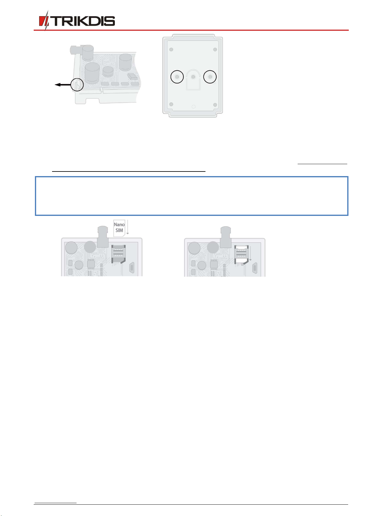
1. Before beginning, make sure that the GSM signal level is sufficient in the place where the CG17 will be mounted.
2. Remove the top lid, remove the plug parts of both terminal blocks.
3. Remove the PCB.
www.trikdis.com 8 March, 2019
Cellular security control panel
CG17
4. Fasten the base of the casing in the desired place using screws.
5. Reinsert the PCB and terminal blocks.
6. Screw the GSM antenna in.
7. Insert a nano-SIM card. The SIM card must already be activated in the GSM network and all required services must be
enabled, i.e., the card must be able to call, send and receive SMS messages, use mobile internet. Ask your SIM card’s
mobile network operator how to enable the required services.
Note: Make sure that the SIM card is activated.
Make sure that the mobile internet service is turned on if connection via the IP channel will be used.
If you do not want to enter the PIN code in TrikdisConfig, insert the SIM card into a mobile phone and disable
PIN code requests.
8. If you want to be able configure the CG17 remotely, insert a SIM card with disabled PIN code requests. Send an SMS
message: CONNECT 123456 PROTEGUS=ON,APN=INTERNET
9. Remote configuration is described in chapter 4.5 “Setting parameters remotely”.
10. Close the top lid.

www.trikdis.com 9 March, 2019
Cellular security control panel
CG17
Schematics for connecting iO series extension modules
Note:
If the wire connecting the temperature sensor is longer than 0,5 m, it is recommended to use a twisted pair cable
(UTP4x2x0,5 or STP4x2x0,5).
To one CG17 you can connect:
o Up to four iO-MOD modules.
o Up to eight iO or / and iO-WL modules.
iButton key readers and temperature sensors should be connected to the 1-Wire terminal.
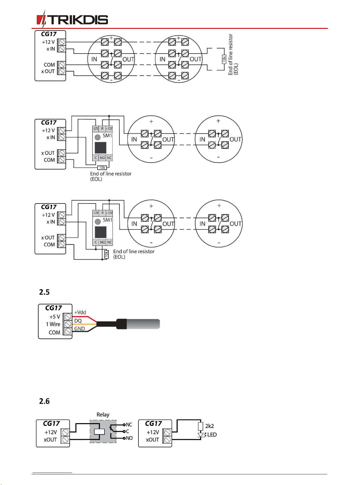
Schematics for connecting inputs
The CG17 has four inputs IN for connecting various alarm system sensors. Possible ways to connect a sensor: NO – normally
open contact; NC- normally closed contact; EOL – normally closed circuit with a 10kΩ end of line resistor. Possible connection
schematics:
Schematics for connecting a smoke detector
Assign a PGM output the function Fire sensor reset (see TrikdisConfig window “PGM” –> “Outputs” tab) so that the smoke
detector can be restarted after an alarm.
Connecting a four-wire smoke detector
www.trikdis.com 10 March, 2019
Cellular security control panel
CG17
Connecting a two-wire smoke detector
a) using an EOL zone (or NC, no resistor).
b) using an EOL zone (or NO, no resistor).
*SM1 – a compatibility module made by Trikdis that allows to remotely restart a two-wire smoke detector after a triggered
alarm.
Schematics for connecting a temperature sensor
Temperature sensors should be connected according to the
given schematic. Maxim®/Dallas® DS18S20, DS18B20
temperature sensors (up to 8 units) can be connected to the
CG17.
If the wire connecting the temperature sensor is longer than
0,5 m, we recommend using a twisted pair cable
(UTP4x2x0,5 or STP4x2x0,5).
Wire colors:
RED – Vdd, connect it to the +5 V terminal;
YELLOW – DQ, connect it to the 1-Wire terminal;
BLACK – GND, connect it to the COM terminal.
Schematics for connecting a relay and a LED

www.trikdis.com 11 March, 2019
Cellular security control panel
CG17
Schematics for connecting contact key readers
The TM17 reader should be connected to the CG17 using an RS485 data bus. The wire length of an RS485 data bus can be up to
300 m.
The iButton key reader should be connected to the CG17 using the “1 Wire” port. The wire length can be up to 30 m:
Note: Linking keys to the CG17 is described in chapter 33.4.1 „Registration of contact (iButton) keys”.
Schematic for connecting a wireless sensor RF-SH transceiver
The wireless sensor RF-SH transceiver is meant for working with Crow brand wireless devices (movement sensors, magnetic
contacts, siren, remote controllers etc.).
Schematics for connecting a siren
A siren that draws up to 1 A of current can be connected to the output
5 OUT or output 6 OUT.
A siren that draws up to 100 mA of current can be connected to any
output OUT.
The output OUT must be assigned the function “Siren” and must have
a security system area set.

www.trikdis.com 12 March, 2019
Cellular security control panel
CG17
Schematics for connecting of the fuel level sensor Strela RS485
Configuring and preparing the fuel level sensor to work with the CG17
It is mandatory to calibrate the fuel level sensor “STRELA S485” (http://strela-fls.com/products/fuel_level_sensors_strela.html)
using the manufacturer’s calibration software DUTConfig (http://strela-fls.com/programs.html) and specify the fuel tank’s
capacity – otherwise the sensor’s measurements can be imprecise.
1. Connect the fuel level sensor to a computer using a programming adapter. Press the „brown” button on the adapter to
make the green indicator in the RS-485 UART section light up.
2. Launch the DUTConfig program. Choose “Interface sensor”.
3. Set View mode Standart.
4. Click Connect and wait.
5. When the sensor is connected to DUTConfig, a box Connection: on appears.

www.trikdis.com 13 March, 2019
Cellular security control panel
CG17
6. Click the “Edit” button and calibrate the sensor in full and empty tank modes.
7. Calibrating under real conditions: a) Fuel tank is full and the sensor is inside the fuel tank – click the button Full tank;
b) Fuel tank is empty, when the sensor is removed from the fuel tank – click the button Empty tank.
8. Click the OK button to save the values.
9. Change the View mode to Extended.
10. Fill in the table according to the shape of the fuel tank. Simple method: just set 0% immersion as 0 litres and 100%
immersion as the capacity of your fuel tank (the fuel tank in the example has a capacity of 200 l).
11. After you are done filling in the table, click OK.

www.trikdis.com 14 March, 2019
Cellular security control panel
CG17
12. Click the Disconnect button.
13. Disconnect the fuel level sensor and connect it to the CG17.
Schematics for connecting a battery
A 12 V battery can be connected to the CG17. If AC power is lost, an event message “AC fault” will be sent and the CG17 will
automatically switch to the 12 V battery.
When the battery’s voltage drops to 11,5 V, an event message “Battery low” will be sent.
When the battery’s voltage drops bellow 9,5 V, if there is no AC power, the CG17 will turn off.
When AC power is restored an event message “AC restore” will be sent and the battery charging process will start
automatically.
When the battery’s voltage rises to 12,6 V, an event message “Battery restore” will be sent.
Connecting the battery:
Insert the backup battery into the casing.
Connect the battery’s wires to the CG17’s backup power source
contacts BAT+ / BAT–.
Check to make sure the CG17’s charging current is sufficient to charge
the battery.
Setting parameters using TrikdisConfig software
1. Download the configuration software TrikdisConfig from www.trikdis.com/ (enter “TrikdisConfig” in the search field) and
install it.
2. Remove the lid of the CG17 using a flat-head screwdriver as shown below:

www.trikdis.com 15 March, 2019
Cellular security control panel
CG17
3. Connect the CG17 to a computer using a USB Mini-B cable.
4. Launch the configuration program TrikdisConfig. The program will automatically recognize the connected device and will
automatically open the CG17 configuration window.
5. Click the Read [F4] button to see the current parameters of the CG17. If prompted, enter the administrator or installer
code in the pop-up window.
Description of TrikdisConfig status bar
Once the CG17 is connected to the TrikdisConfig software, the program will display information about the connected device in
the status bar:
Status bar
Name Description
IMEI/Unique ID The device’s IMEI number
Status Operational state
Device Device type (must show CG17)
SN Device’s serial number
BL Bootloader version
FW Device’s firmware version
HW Device’s hardware version
State Type of connection with the program (USB or remote)
Role Access level (shown after access code is approved)
Note: Click Read [F4] to make the program read and display the settings that are currently saved on the device.
Click Write [F5] to save the settings displayed on the screen to the device.
Click Save [F9] to save the settings to a configuration file. You can upload the saved settings to other devices
later. This allows to quickly configure multiple devices with the same settings.
Click Open [F8] and choose a configuration file to view previously saved settings.
If you want to revert to the default settings, click the Restore button at the lower left of the screen.
When the Read [F4] button is clicked, the program will read and show settings currently saved on the CG17. With TrikdisConfig,
set the required parameters using the following program window descriptions.

www.trikdis.com 16 March, 2019
Cellular security control panel
CG17
“System Options” window
“System general” tab
Settings group “General”
If events are going to be sent to the CMS, enter the Object ID (4-symbol hexadecimal number, 0-9, A-F) given by the CMS.
Object name will be used in SMS messages about events (up to 20 symbols, letters and numbers can be used).
Test period – when the box is ticked, periodic “Test” messages will be sent every set period.
Areas in test SMS – the states of chosen areas will be sent in the test message.
Time synchronization – choose a server to synchronize time with. If you choose “IP server”, time will be synchronized
with the IP receiver’s time, if you choose “GSM modem”, time will be synchronized with the GSM service provider’s server
time.
Clear Events after reset – all unsent event messages will be deleted after reset.
SMS language – set the preferred language and the specific symbols of that language will be used in SMS messages.
You can Suspend event reporting when ... a number of same events per ... s happen.
Restore event reporting after ... – set the time after which suspending of event reporting will be cancelled. The time can
be anywhere from 0 to 999 minutes.
Call – after an event, the CG17 will call user(s) as many times as is specified. If the call is declined or answered, the CG17
will stop calling. Call time is 20 seconds.
Settings group “SIM”
Enter SIM card PIN code.
APN – service provider’s mobile internet access point name. You must enter the APN if event messages will have to be
sent to Protegus cloud service or to the CMS via GPRS.
If the SIM card’s GPRS service provider requires, enter the APN user name and password in the fieds Login and Password.
Settings group “Area Settings”
Area(-s) number sets the number of independent parts of the alarm system.
If the siren is connected and an output OUT (must be allocated to an area) is set as “Siren”:
Siren duration – duration of siren operation when the alarm is triggered. Time is anywhere from 0 to 999 seconds.

www.trikdis.com 17 March, 2019
Cellular security control panel
CG17
Siren squak on arm/disarm – the siren will make a short sound once when the alarm is armed and twice when it is
disarmed.
Entry time – time for entering through the “Delay” zone. Time is anywhere from 0 to 999 seconds.
Exit time –time for exiting through the „Delay” zone. Time is anywhere from 0 to 999 seconds. When the alarm is armed
using the Protegus app or phone call, the system will not count the Exit time.
Keyswitch sets the alarm’s arm/disarm mode using the “Keyswitch” zone. You can choose control using Pulse or Level.
“Access” tab
Settings group “Access codes”
Administrator Code – (default code - 123456) gives full access to configuration (the code must be 6 symbols long; it must
consist of latin letters and/or numbers).
SMS password – (default code - 123456) is for safety when controlling with SMS messages. To ensure more safety, change
it to a 6-symbol code only you know.
Installer Code – (default code - 654321) gives the installer access to configuration. To ensure safety, change it to a 6-
symbol code only you know.
Note: If the default administrator code is set (123456), the software will not require it to be entered and clicking
Read [F4] will immediately show the parameters currently saved on the device.
Settings group “Installer permissions”
For setting installer’s rights.

www.trikdis.com 18 March, 2019
Cellular security control panel
CG17
“Reporting to CMS” window
Settings groups “Primary channel” and “Backup channel”
Communication type – choose a protocol for communication with the receiver (TCP/IP, UDP/IP, SMS).
Domain or IP – enter the receiver’s domain or IP address.
Port – enter the receiver’s network port number.
Protocol – TRK for event transfer using Trikdis receivers, SIA DC-09 for event transfer using universal receivers.
Phone number – phone number of CMS receiver capable of receiving SMS messages.
Encryption Key – 6-digit message encryption key that must match the encryption key of the CMS receiver.
Settings group “Settings”
Return to primary after – time period after which the CG17 will attempt to regain connection with the primary channel,
in minutes.
IP Ping period – period for sending PING signals for checking connectivity on the GPRS channel, in seconds. To enable
these signals, tick the box.
SMS PING period – period for sending PING signals for checking connectivity on the SMS channel, in minutes. To enable
these signals, tick the box.
Backup reporting after – enter how many failed attempts to send messages using the primary channel should happen
before switching to the backup channel.
DNS1 – DNS2 – DNS server addresses.
Object ID in SIA DC-09 – specify object number.
SIA DC-09 receiver No. – specify receiver number.
SIA DC-09 line No. – specify line number.
Settings group “Backup channel 2”
Phone number – phone number of an CMS receiver capable of receiving SMS messages (e.g.: 370xxxxxxxx). The backup
SMS channel is used when messages fail to send using the primary and backup channels. This function is extremely useful
because it works even when IP connectivity is disrupted in the mobile operator’s network. This channel only works when
GPRS mode is set both for the primary and backup channels. SMS messages will be sent to the receiving center: 1) as
soon as the CG17 is turned on for the first time; and 2) after loss of TCP/IP or UDP/IP connectivity on the primary and
backup channels.

www.trikdis.com 19 March, 2019
Cellular security control panel
CG17
“Users & Reporting“ window
“Users” tab
Settings group “Users & Reporting to User”
ID – user’s number on the list.
Name / E-mail – user’s name or e-mail. These names will be used in SMS messages about events. An administrator can
specify a user's email. This will allow the user to log in to Protegus
Tel number – user’s phone number. This number can control the alarm remotely and will receive SMS messages. The
numbers must be entered with the international code.
Code – the code for arming and disarming the alarm given for each user.
Areas – areas the user can control. User ID9 can control only area 1, parameter is uneditable.
A – tick the box if you want to allow the user to ARM the alarm.
D – tick the box if you want to allow the user to DISARM the alarm.
If PGM and REC boxes are not ticked, but both A and D are selected, when the user calls the CG17, their call will be
declined, and the alarm will change its operational status to the opposite state, i.e., the alarm will be armed or disarmed.
If only PGM is ticked, the user can call the CG17 and turn on or turn off a desired output using DTMF tone commands.
If only REC is ticked, the user can call the CG17 and change the voice recording for events using DTMF tone commands.
ACK – if the box is ticked, the CG17 will send the user messages with SMS answer text after every command received in
SMS messages.
FWD – tick this box if you want to forward SMS messages received from non-system users (e.g., SIM card account balance,
random promotional messages, etc.) to the user.
Settings group “PROTEGUS Cloud”
Enable connection – enables Protegus service, so that the CG17 can exchange data with the Protegus app. Also allows
remote configuration with TrikdisConfig.
Parallel reporting – enable parallel sending of messages using the main channel and to Protegus.
Protegus Cloud Code – 6-digit code for connecting with Protegus.

www.trikdis.com 20 March, 2019
Cellular security control panel
CG17
Settings group “iButtons”
Note: More than one key can be assigned to a user! All newly registered keys will be assigned to the User ID9 (No
name). Names can be assigned only to eight users. Permissions for User ID 9 can be set using the settings group
User ID9 permissions.
ID – key’s number on the list.
User – the user the key is assigned to. To assign a key to a user, change ID9 to any other user’s ID from the table “Users
& Reporting to User”. (e.g. to assign a key to user No. 3, change ID9 to ID3)
iButton code –iButton key identification number.
Control – choose what action the system must take after reading the key (e.g., TM17): None / Arm / Disarm / Arm &
Disarm.
3.4.1 Registration of contact (iButton) keys
1. If the “iButtons” list is empty, the first registered key is saved to the first line of the list and becomes the Master key.
2. To turn on contact key registration mode, hold the Master key against the key reader for at least 10 seconds. When
registration mode is on, the TM17 key reader’s LED indicator “State” will start to blink in green.
3. To register user keys, hold them against the key reader one by one. 3 sound signals from the reader will indicate that the
key has been registered.
4. When you finish registering the user contact (iButton) keys, hold the Master key against the key reader again to turn off
registration mode. When the registration mode is turned off, the “State” LED indicator of the TM17 key reader will stop
blinking.
5. To delete all keys (including the master key), hold the Master key against the reader for at least 20 seconds.
Important: The Master key should only be used to register other contact keys!
“SMS answer texts” tab
Settings group “SMS answer texts”
Texts of answers to control commands sent using SMS messages can be edited in the field SMS text.
Table of contents
Other Trikdis Control Panel manuals


