TRIMALCO ATHENA 70 User manual


Introduction
Thank you for purchasing this Table Top Cutter. It has been manufactured in the UK to the highest
standard and if used in accordance with these instructions and properly maintained, it will give you
years of trouble-free performance.
e want your experience using this machine to be exceptional, so for maximum safety and
productivity, please read and understand this manual thoroughly before operating.
Product warranty
The manufacturer warrants the machine purchased to be free from defects in parts and
workmanship for five (5) years from the date of purchase. The manufacturer warrants that it will
repair or replace any such defective machine or replace parts, providing the machine has been
under normal use and service and the defective part or machine is returned to the manufacturer at
the purchaser’s expense. The manufacturer must authorise the return in writing. Proof of
purchase must be submitted to validate warranty coverage. The warranty is in lieu of all other
agreements and warranties expressed or implied.
THE MANUFACTURER DOES HEREBY EXPRESSLY DISCLAIM ANY ARRANTIES OF MERCHANTABILITY
OR FITNESS FOR A PARTICULAR PURPOSE. The manufacturer does not authorise any company
employee or representative to assume for it any other liability than that set forth in this Product
arranty. The manufacturer shall not be liable for any damages or losses, whether incidental or
consequential, direct or indirect, arising out of the use or abuse of this machine. This arranty is
valid only when the machine is used with the manufacturer’s consumables and replacement parts.
In any event, THE PURCHASER’S SOLE AND EXCLUSIVE REMEDY UNDER THIS OR ANY OTHER
ARRANTY IS LIMITED TO RETURN OF THE PURCHASE PRICE PAID FOR THIS MACHINE.
Safety first !
Please read through this manual before operating this Table Top Cutter. If after reviewing these
pages you still have questions about the safe use of this machine, contact your supplier.

1Contents
2 Packing list
2.1 Unpacking your machine
3 Before set up
3.1 Checking the work table for installation
3.2 Checking and adjusting the worktop for flatness
3.3 The base locating brackets
3.4 Positioning the base locating brackets
3.5 Fitting the cutter assembly
4 Set up
4.1 Adjusting the cutting groove alignment
4.2 The rotating mechanism
4.3 The integral levelling adjustment
4.4 Checking and adjusting for flatness and grip
4.5 Building up the table top surface
5 Operation
5.1 Inserting the material to be cut
5.2 Blades and blade holders
5.3 Using the utility blade holder
5.4 Using the scoring blade holder
5.5 Using the rotary blade holder
Maintenance
6.1 Cleaning and lubrication
6.2 Adjusting the cutting head bearings
7 Fitting to the Atlas for Athena Table
7.1 Fitting to the Atlas for Athena Table
1 CONTENTS 1

NOTE: HEN LIFTING THE MACHINE FROM THE
BOX, ENSURE THAT T O PEOPLE ARE USED FOR
LIFTING. THE MACHINE COMES FULLY
ASSEMBLED AND THE LONGER MODELS ARE VERY
HEAVY.
After unpacking your machine, check with the lists
below and the photographs opposite to make
sure that you have all the parts and that there is
no damage.
Your machine comprises of the following items:
ATHENA A3 CUTTER
A3 FIXINGS BAG
CUTTER RAIL ACCESSORY BAG
Fastenings can come loose in transit. Do not
throw any packaging away until installation is
complete.
2.1 UNPACKING YOUR MACHINE 2.1
CHECKING THE WORK TABLE FOR INSTALLATION
The cutter can be fixed to one of our purpose built
tables or it can be fitted to an existing table. The
table needs to be rigid with a flat worktop made
from MDF or similar and capable of accepting the
fixing screws. The table top needs to be flat to
within 3mm (1/8”)
To enable the flip-over storage function to
operate, the cutter must be fitted along the front
edge of the worktop.
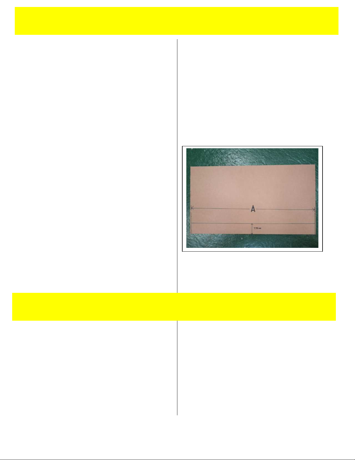
If the cutter is to be mounted along the front
edge, draw a line 7.75 cms (3.1”) in from, and
parallel, to the front edge. The line “A”, should be
the overall length of the cutter.
70cms (28”) A = 90cms (36”)
110cms (44”) A = 130cms (52”)
160cms (64”) A = 180cms (72”)
210cms (84”) A = 230cms (92”)
260cms (104”) A = 280cms (112”)
310cms (124”) A = 330cms (132”)
360cms (144”) A = 380cms (152”)
Should you wish to use the cutter say 15cms (6”)
from the front edge then draw the line 15 + 7.75 =
22.75cms (9.1”) from, and parallel to, the front
edge.
CHECKING AND ADJUSTING THE WORKTOP FOR
FLATNESS
You can check the flatness of the worktop by
stretching a thin piece of strong thread between
two blocks of the same height. Measure the
highest and lowest part of the worktop under the
thread, the difference should not exceed 3mm
(1/8“). If the difference is greater it will be
necessary to adjust the flatness with a new top or
by using spacers under each locating bracket.
3.1 BEFORE SET UP 3.1
3.2 BEFORE SET UP 3.2
CHECKING AND ADJUSTING THE WORKTOP FOR
FLATNESS (continued).
Adjust the surface flatness by adding packing
pieces, made from 1.5mm-3mm (1/16” – 1/8”)
thick rigid material such as PVC Foamboard, under
the mounting plates during installation (see 3.3).
THE BASE LOCATING BRACKETS & MOUNTING
PLATES
The base locating brackets and mounting plates
are designed to hold the base of the cutter firmly
in place and provide a means to adjust the base
for both flatness and alignment of the cutting
groove. Before fitting the brackets, check that the
tips of the grub screws are aligned with the inside
of the bracket. These are factory set but may
have moved in transit. Check that the jacking
screws are present and are finger tight.
IF YOU ARE FITTING THE ATHENA 3 TO THE ATLAS
FOR ATHENA TABLE PLEASE PROCEED TO 7.1
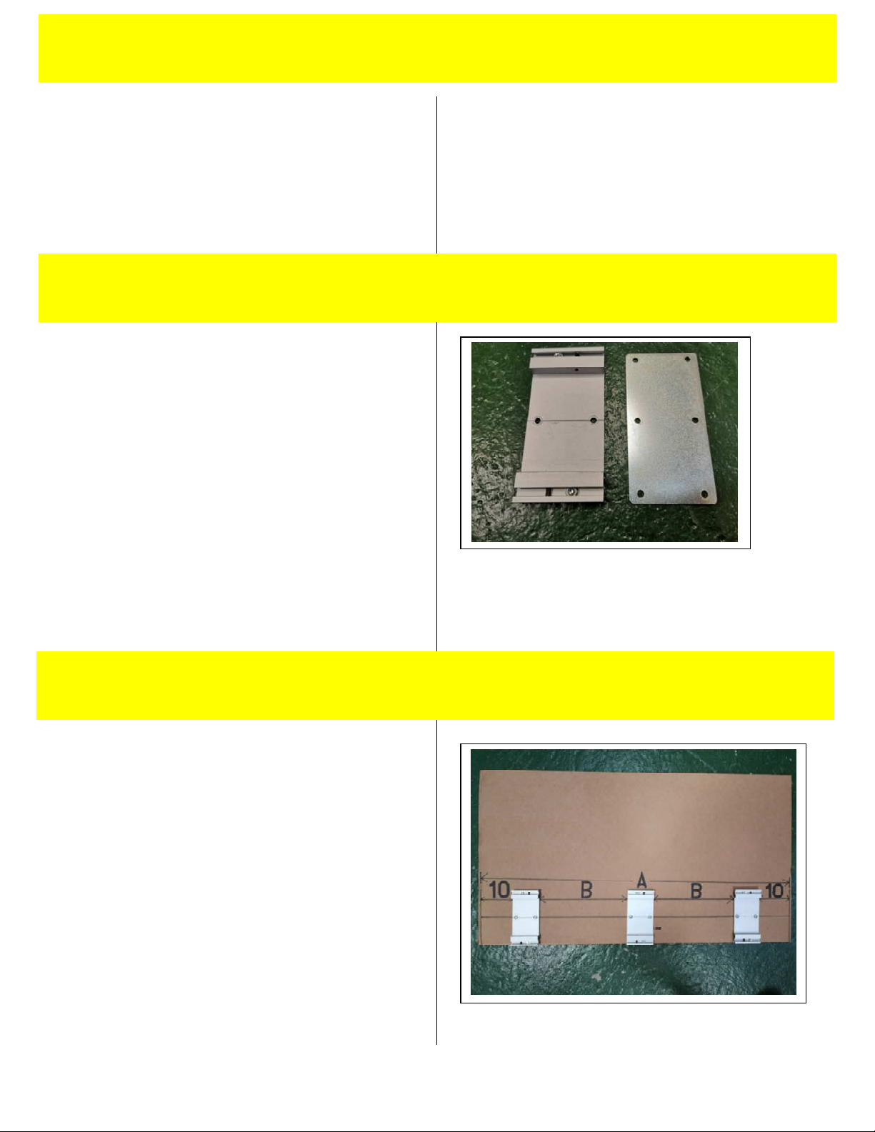
POSITIONING THE BASE LOCATING BRACKETS &
MOUNTING PLATES
Position a bracket & plate 10 cms (4”) inboard
from either end of the line drawn as described in
3.1, ensuring that the centre of the bracket is
aligned with the pencil line and fix to the worktop
using the screws provided. Position the remaining
brackets accurately along the line with equal
spacing (B) between each bracket. Check that all
brackets are aligned correctly and if not, remove
any incorrectly positioned brackets slightly to one
side of the original position to create new screw
holes.
3.3 BEFORE SET UP 3.3
3.4 BEFORE SET UP 3.4
3.2 BEFORE SET UP 3.2

FITTING THE CUTTER ASSEMBLY
Lift the cutter assembly and place it centrally on
the locating brackets. The larger cutters are
heavy and this will require two people.
Remove the clear stretch wrap and gently
manoeuvre the assembly until it is located
properly on each of the brackets.
Tighten the grub screws at the back of each
bracket (see 4.1 picture 1) by 8 full turns and then
tighten the front grub screws (see 4.1 picture 2)
up fully (approx 7-8 turns).
ADJUSTING THE CUTTING GROOVE ALIGNMENT
The cutter bar is guaranteed to be straight to
within 0.4mm (.016”) along its full length. If you
need to adjust the cutting groove in the base to
match this, the base brackets provide the means
to do so.
Adjust the straightness of the base by adjusting
the front and rear grub screws in the base locating
brackets.
To move the cutting groove towards the back of
the table, loosen the rear grub screw in the
nearest bracket and tighten the front grub screw
until the groove is aligned. Tighten the rear grub
screw. To move the cutting groove towards the
front of the table, loosen the front grub screw and
reverse the sequence above.
3.5 BEFORE SET UP 3.5
4.1 SET UP 4.1

ADJUSTING THE CUTTING GROOVE ALIGNMENT
(cont).
If you find that there is insufficient base alignment
using the adjusting screws it is probable that one
or more of the brackets need to be removed and
realigned on the table top.
THE ROTATING MECHANISM
Insert two of the four wood screws provided in
the front holes of the fixed arm and screw them
into the worktable but do not tighten.
Loosen by one full turn anti clock-wise, the four
hexagon screws (two at each end) joining the
fixed arms to the cutter base. Now fully insert the
two wood screws.
hen not in use, the cutter bar can be rotated to
a safe position under the cutting table leaving the
work surface free for performing other
procedures.
NOTE: ASSISTANCE MAY BE REQUIRED, THE
LONGER VERSIONS OF THESE CUTTERS CAN BE
HEAVY
Carefully rotate the bar and place the remaining
two wood screws into the two holes towards the
rear of the fixed arms. Now tighten all four
hexagon screws.
4.2 SET UP 4.2
4.1 SET UP 4.1

THE INTEGRAL LEVELLING ADJUSTMENT
It is essential that the material being cut is held
securely in the cutter during the cutting process.
There are two silicon cords on the underside of
the cutter bar and one in the base to assist with
this.
There is an integral levelling adjustment that
allows the cutter bar to sit flat on any thickness of
material. Place the material to be cut under the
cutter bar and release the both knobs (RH shown
opposite). The cutter bar will settle and sit on the
surface of the material. Raise the cutter bar using
the yellow lift handle and lower again to ensure
correct alignment. Now tighten both knobs.
CHECKING AND ADJUSTING FOR FLATNESS AND
GRIP
Check the grip of the cutter bar using a sheet of
copy paper. Starting at one end, raise the cutter
bar and place the paper under it. hen lowered,
the weight of the cutter bar should grip the paper.
Try to pull the paper free, you should feel
resistance. If there is not sufficient resistance,
note its position and work your way along the
cutter repeating the paper test and noting where
it is not clamping.
Adjust the clamping using the jacking screws in
the locating brackets next to the areas where the
clamping is insufficient. Turning the screws
clockwise as you look down on them will lift the
base. Adjust the front and back screws by the
same amount until the resistance is sufficient.
You may find that two or three adjacent brackets
need to be adjusted if a wide area does not
provide sufficient clamping.
4.3 SET UP 4.3
4.4 SET UP 4.4

BUILDING UP THE TABLE TOP SURFACE
Once the cutter has been installed, all that
remains is to raise the level of the surrounding
surface by 19mm (3/4”). The best way of doing
this is to add a new work top made from MDF or
similar.
The worktop should not extend beyond the edges
of the base extrusion.
4.5 SET UP 4.5

INSERTING THE MATERIAL TO BE CUT
Use either lift handle to raise the cutter bar. Place
the material to be cut on the base and then lower
the cutter. To align the edge of the cutter bar
with your crop marks, slightly raise the cutter bar
and adjust the position of the material at both
ends. The blade will cut close to the edge. This
small gap is intentional and allows easier
alignment when cutting to the edge of an image.
Check that the width of the cutting bar (front
edge to back) is lying flat on the surface of the
material to be cut. If not, loosen both tilt
adjustment knobs, raise and then lower the cutter
to settle it into position and tighten both knobs.
The cutter is now ready to cut all materials of that
thickness.
The flip stop is provided to prevent tough
materials such as PVC Foamboard from moving
during cutting.
If you are cutting a small piece of board, place it
against the flip stop and place scraps of the same
thickness material along the length of the cutter
bar to support it.
BLADES AND BLADEHOLDERS
All cutters come with two different blade holders
as standard. One blade holder accepts Medium
Duty Blades as well as a Scoring Blade for acrylic
and other rigid plastics. A separate blade holder
takes a rotary blade which is ideal for textiles and
thinner materials.
To fit a blade holder, loosen the BLADE CLAMP
THUMB SCRE and insert a cartridge. The utility
blade and scoring blade cartridge is inserted from
the rear of the holder and the textile blade
cartridge is inserted from the front.
5.1 OPERATION 5.1
5.2 OPERATION 5.2
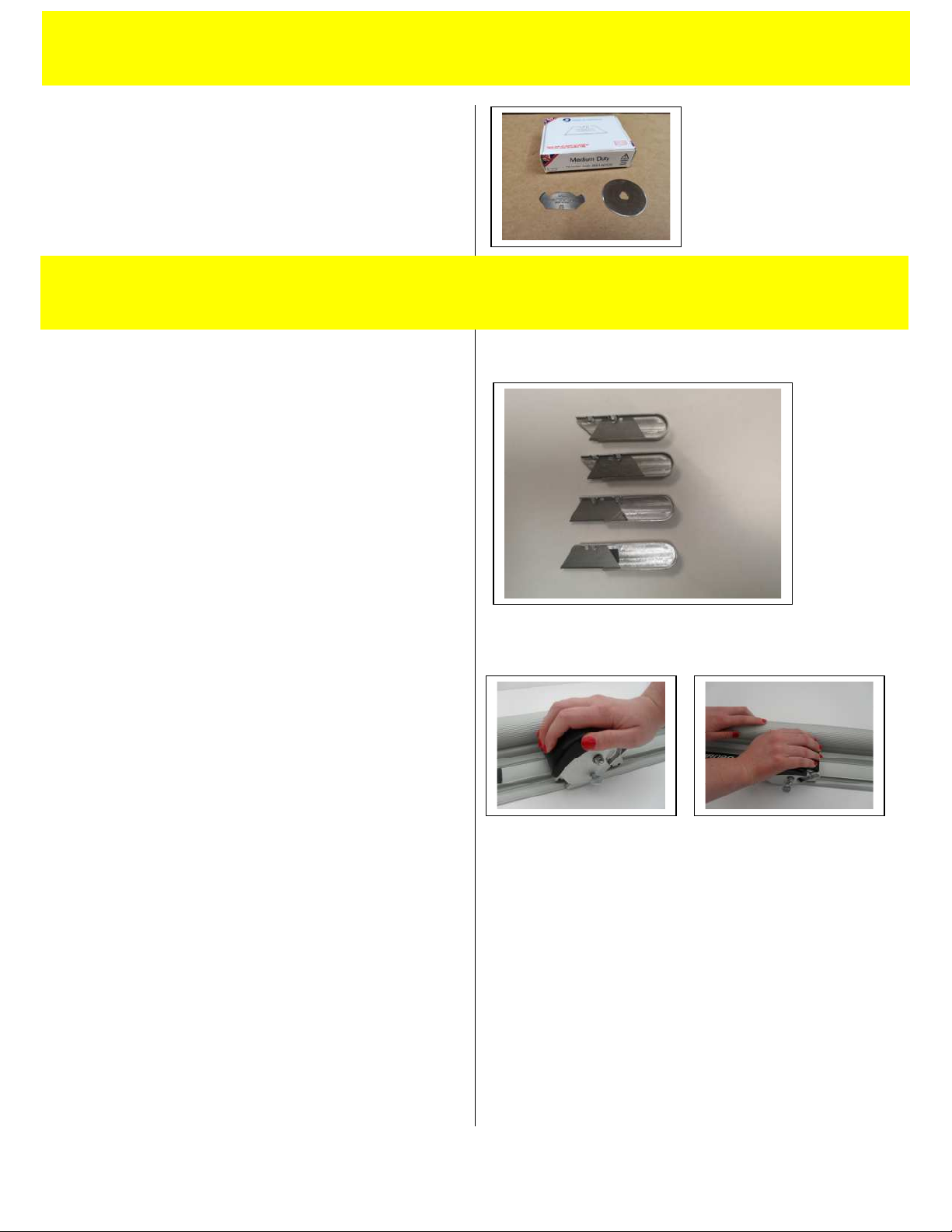
herever possible it is our policy to use standard
blades. Each cutter comes with 100 x Medium
Duty Utility Blades, 1 x Scoring Blade and 1 x
Textile heel. All of these blades are available
from your distributor.
USING THE UTILITY BLADE HOLDER
Blade depth is important and should be set so
that the blade will cut through the thickness of
material being cut plus 1mm. Avoid setting the
depth too deep so that the blade tip hits the
bottom of the cutting groove.
The utility blade can be located in any one of four
positions allowing materials up to 19mm (3/4”)
thick to be cut. Fine adjustment of the blade
depth can be carried out by undoing the BLADE
CLAMP THUMB SCRE and moving the cartridge
itself.
To cut lightweight materials, place your right hand
on the cutter head, depress the cutter and pull
the cutting head towards you. To cut
heavyweight materials, place your left hand on
cutter bar and apply downward pressure, place
your right hand on the cutter head, depress the
cutter with the palm of your hand and push away
from you to cut. Multiple passes may be needed
for thicker materials.
The cutting head requires no dexterity and can be
easily used with the right and left hands.
5.3 OPERATION 5.3
5.2 OPERATION 5.2
USING THE SCORING BLADE HOLDER - The
scoring blade should be located in the cartridge as
shown opposite. To score fracture sensitive
plastics such as acrylic use the same technique as
used for cutting heavyweight materials (see
above). To break, move the material so that the
score line runs along the front edge of the table
and using the cutter as a clamp, apply downward
pressure to the overhanging plastic to break.
(SAFETY GLASSES AND GLOVES SHOULD BE
ORN)
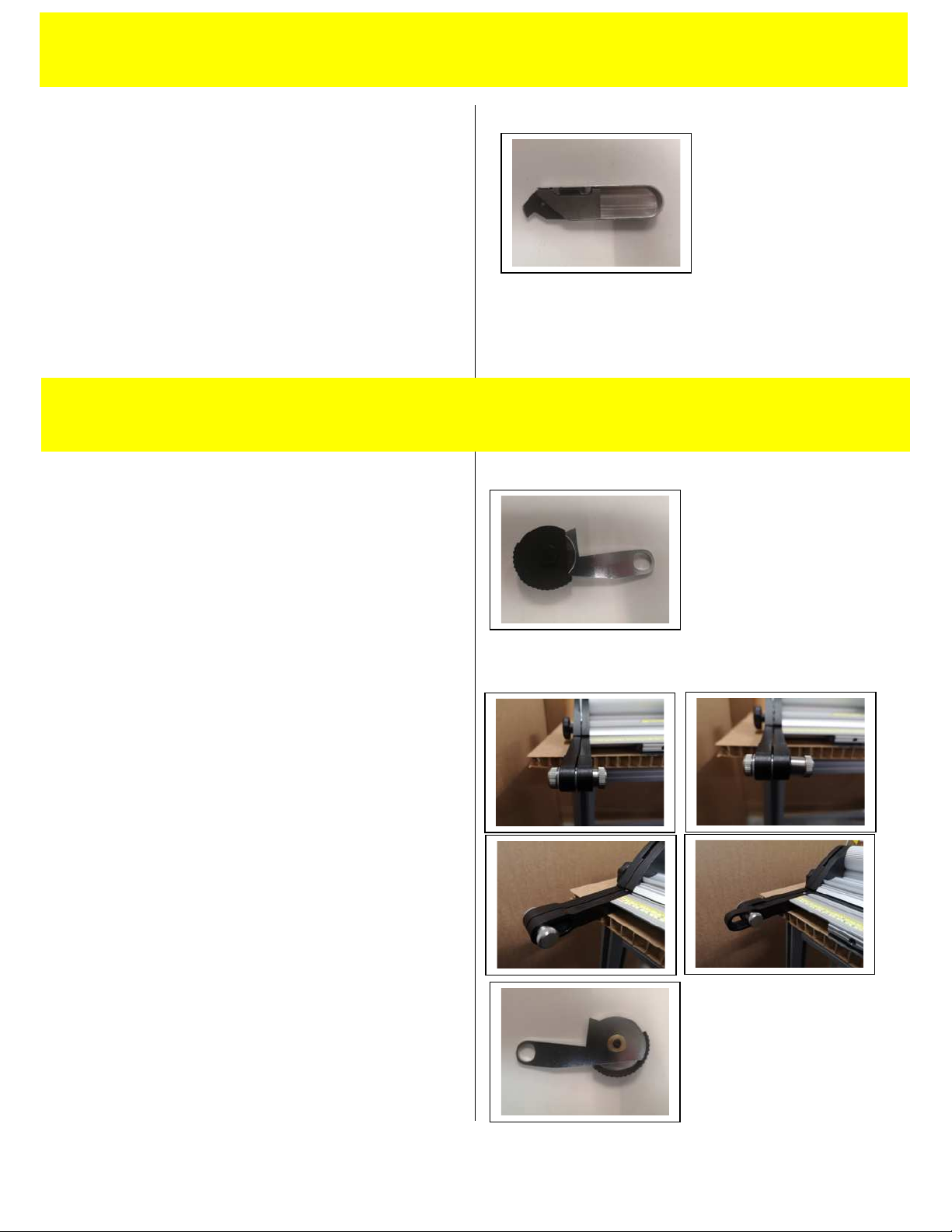
USING THE ROTARY BLADE HOLDER
The rotary cutter blade holder supplied with this
machine is used to cut textiles, thin paper and
other flimsy material. It uses a circular blade to
press down onto the substrate to be cut. The
substrate being cut is supported by a plastic
cutting strip embedded in the base of the
machine. The blade guard makes it safe to handle
but be careful as the blade is very sharp.
To change the cutting channel, first raise the
cutter bar using the Lift and Hold lever. Then
loosen both of the hinge location screws until the
underside of the screw clears its location recess.
Push the cutter bar back until the underside of the
location screw lines up with the rear recess and
tighten the hinge location screw. Repeat at the
other end. The cutter bar is now positioned over
the plastic cutter strip.
The cutting strip can also be removed, turned
around or flipped over allowing four tracks to be
used before the strip requires replacement.
Replacement strip are available from your dealer.
CHANGING THE ROTARY BLADE
Blades can be replaced by undoing the knurled
brass knob on the rear of the unit.
5.4 OPERATION 5.4
5.5 OPERATION 5.5

CLEANING AND LUBRICATION.
Regularly clean your Cutter rail using a dry cloth,
stubborn stains can be removed with a cloth
dampened with a little water/detergent.
Silicon spray can be used to lubricate the cutting
head slideway.
NEVER USE OIL OR SPIRITS TO LUBRICATE OR
CLEAN THE CUTTER RAIL, SOME OF THE PLASTIC
COMPONENTS AND BEARINGS MAY BE DAMAGED
CUTTING HEAD BEARINGS
The bearings used to control the sliding motion of
the CUTTING HEAD are made from a high-quality
polymer and under normal use will last for an
extremely long time. As they settle into position
you may find a slight amount of side play, this can
be removed by tightening the two adjustment
screws.
Place the long end of the 2mm Allen key provided
into any of the two grub screws and very gradually
tighten with one hand while moving the cutting
head along the cutter bar with the other. Once
you feel the sliding motion begin to tighten, undo
the screw the smallest amount, allowing the
cutting head to slide easily.
Repeat this for the other screw.
6.1 MAINTENANCE 6.1
6.2 MAINTENANCE 6.2

POSITIONING THE BASE LOCATING BRACKETS &
MOUNTING PLATES
Position a bracket & plate assembly 10 cms (4”)
inboard from either end of the Athena Support
Beam. Position the remaining assemblies along
the length of the Athena Support Beam with equal
spacing between each. If one of the bracket
assemblies coincides with a centre frame beam
simply move that bracket to either side of the it.
FITTING THE CUTTER ASSEMBLY
Lift the cutter assembly and place it centrally on
the locating brackets. The larger cutters are
heavy and this will require two people.
Remove the clear stretch wrap and gently
manoeuvre the assembly until it is located
properly on each of the brackets. Slide the
assembly left or right so that the holes in the fixed
arms line up with holes in the support brackets
fitted to the table. Insert the four button head
screws and nuts (included with the table) at this
point but do not tighten.
Loosen by one full turn anti clock-wise, the four
hexagon screws (two at each end) joining the
fixed arms to the cutter base (see 4.2). Now
tighten the four button head screws fully insert
the two wood screws.
Tighten the grub screws at the back of each
bracket (see 4.1 picture 1) by 8 full turns and then
tighten the front grub screws (see 4.1 picture 2)
up fully (approx 7-8 turns).
The cutter bar is guaranteed to be straight to
within 0.4mm (.016”) along its full length. If you
need to adjust the cutting groove in the base to
match this, follow the instructions in 4.1
7.1 FITTING TO THE ATLAS TABLE 7.1

This manual suits for next models
6
Table of contents
Other TRIMALCO Cutter manuals


