TriMark e-ASK UM27 User manual

e-ASK
electronic Access Security Keyless-entry
CAN Multiplex System
Installation & Instructions
(UM27 ~ 24324-03)

Table of Contents
Introduction .................................................................................. 1
e-PAD Operation and Features................................................... 1
Locking Doors With Keypad ...................................................... 1
Unlocking Doors With Keypad................................................... 1
e-FOB Operation and Features.................................................. 2
Additional Features...................................................................... 2
Dome/Porch Light Activation ..................................................... 2
e-PAD Anti-tamper Deactivating Feature.................................. 2
Teaching Keypad New Authority/Access Codes...................... 2
Assign New Access Codes........................................................ 3
Teaching Additional Transmitter FOBs ..................................... 4
e-ASK CAN DIP Switch Configuration ...................................... 5
Wiring Assignments..................................................................... 7
Troubleshooting........................................................................... 8

Introduction
This manual provides the necessary information for the proper
installation and use of TriMark’s CAN e-ASK system. The e-ASK
system comes with the following components:
e-FOB keyless entry radio frequency [RF] FOB transmitter and
receiver
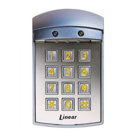
e-PAD keypad user interface
e-PAD Operation and Features
The e-PAD is shipped with default authority and access codes. Unless
the OEM or dealer has changed default codes, the authority and access
codes are as follows:
1
Digit 1 Digit 2 Digit 3 Digit 4 Digit 5
1 / 2 3 / 4 5 / 6 7 / 8 9 / 0
Digit 1 Digit 2 Digit 3 Digit 4 Digit 5
7 / 8 7 / 8 7 / 8 7 / 8 7 / 8
Access code:
Authority code:
Locking Doors With Keypad
Press and hold down the 1 / 2 button for 1-2 seconds. An access code
is not needed to lock the doors.
Unlocking Doors With Keypad
Entering a valid 5-digit access code enables a secure operation. After
entering an access code, the keypad is enabled for 5 seconds and an
additional button press initiates a secure operation, such as unlocking
the doors.
1. Enter access code.
2. Press and release:
1 / 2 button to unlock driver door, or
3 / 4 button to unlock driver and passenger doors
Note:
The authority code does not allow for secure operations. It is
only used to assign access codes (see page 3 for information on
setting codes).
The secure keypad operations are set depending on the system
configuration.

2
e-FOB Operation and Features
Note:
The RF features are an option that may not be available on your
vehicle.
The CAN module and transmitters are shipped programmed.
After making all necessary wiring connections, (see page 6 for
wiring information), the e-FOB system will function as shown.
Additional Features
Dome/Porch Light Activation
The dome light is activated for a timed duration (20 seconds) whenever
the system is unlocked from keypad or FOB transmitter. This is an
optional feature that the OEM may not have installed.
e-PAD Anti-tamper Deactivating Feature
After repeated attempts to enter code (20 button presses without
enabling), the keypad enters an inactive mode that disables button for 1
minute. This helps prevent access by entering random codes. The
keypad does not beep while the system is disabled.
Teaching Keypad New Authority / Access Codes
When a new authority code is assigned, all existing authority and access
codes are erased.
Note: The authority code assigned following these instructions is also an
access code saved to the (1 / 2) button.
1. Touch the yellow wire of keypad to ground. There will be a three-
second beep. When the beep starts, remove the GND.
2. Enter a five-digit code.
3. Enter the new code again.
Button Function
Lock Locks all doors
Unlock Unlocks all doors

Notes:
The authority code is to be controlled by individuals (owners of
vehicle, fleet manager, etc.) who manage the distribution of
access codes to vehicle users.
The authority code should be changed when the vehicle is sold.
The authority code does not enable secure functions (lock/
unlock doors, etc.). It is only used to assign access codes.
The following area can be used to document the authority code:
Authority code:
Assign New Access Codes
With a valid authority code (see page 2), an access code can be
programmed with the following instructions.
1. Press the (5 / 6) button for 5 seconds, the keypad will beep.
(Backlight LEDs of the keypad flash indicating the learn mode.)
2. Enter the 5-digit authority code (see page above). Keypad will
provide a long beep that will stop after you have defined an
access number.
3. Press and release any button. This button corresponds to the
access number being programmed. For example, press (1 / 2)
button for access code #1 and press (3 / 4) button for access
code #2.
4. Enter in your new 5-digit access code. The keypad will provide
3 beeps.
5. Re-enter new access code. The keypad will provide 3 beeps.
Repeat process to assign additional access codes.
Up to 5 different access codes can be assigned at one time.
As additional access codes are defined, pre-existing access
codes are overwritten. For example, if a new access code is
assigned for access #3, the previous access #3 code is no
longer valid.
A one second beep means that an error was made and no
code was programmed.
3
Digit 1 Digit 2 Digit 3 Digit 4 Digit 5

The following area can be used to document the access code
assignments.
Access code:
Teaching Additional Transmitter FOBs
This applies only to the e-ASK system that includes the RF receiver
door module.
There are 2 ways that the receiver can be put into learn mode. The first
requires that a CAN keypad be connected to the network. This option
allows the receiver to be put into train mode without accessing the
module. The 2nd option requires access to the RF receiver door
module.
Option 1 (if CAN keypad is connected to network):
1. Hold middle (5 / 6) button of keypad for 5 seconds. The keypad will
beep and the LEDs will flash.
2. Enter authority code. Keypad will provide a sustained beep.
3. Press and hold (9 / 0) for 5 seconds. A double beep plays.
a. The receiver module is now in FOB Learn Mode. (The LED
under the receiver enclosure will be blinking rapidly—this will
not be visible unless the enclosure cover is removed.)
4. Press lock button of the first FOB to be trained for 2 seconds. Wait
3 seconds and press the lock button on each subsequent FOB. Up
to 4 FOBs can work with the module at one time.
5. Press any button on the key pad to exit FOB learn mode. Four
short beeps will sound and the door module will return to normal
operation.
6. Verify function and range of the FOBs that were trained.
4
Access # Digit 1 Digit 2 Digit 3 Digit 4 Digit 5
1
2
3
4
5

Option 2 (if no CAN keypad is connected to network)
1. Remove power from door module.
2. Open up door module enclosure.
3. Move DIP switches 4-6 to the “ON” position.
4. Connect door module to CAN network.
5. Connect power to door module.
6. Wait 5 seconds. The LED will come on solid and then continue to
flash.
7. Press lock button of the first FOB for 2 seconds until LED pattern
changes (fast flash), then release. This synchs the first FOB
transmitter.
8. Press lock FOB button of 2nd FOB for 1 second, until fast LED
flash. This synchs the 2nd FOB transmitter.
9. Repeat step 8 until all FOBs are synched (up to 4 FOBs).
10. Remove power and CAN from door module.
11. Move DIP switches 4-6 to original position and verify DIP switches
1-3 are in proper position.
12. Reassemble enclosure.
13. Reconnect power and CAN to module.
14. Verify that FOBs are synched to the door module and that range
of RF transmission is acceptable.
e-ASK CAN DIP Switch Configurations
DIP Switches 1-3:
The settings of DIP switches 1-3 define the CAN address of the
module. Each door module must have a unique address.
5
Dipswitch Driver Door Rear Left Rear Right
1 Off Off Off
2 Off On On
3 Off Off On
Front Right
Off
Off
On

6
DIP Switches 4-6:
The setting of DIP switches 4-6 define configuration of the I/O RF
receiver module. Different configurations provide different functionality
for keypad and interior switches. The following configuration allows for
door lock and window control:
DIP Switch 4: Off
DIP Switch 5: Off
DIP Switch 6: Off
DIP Switch 7:
The setting of DIP switch 7 defines the type of remote FOB transmitter,
either standard FOB or cargo FOB.
On: Cargo FOB
Off: Standard FOB (2-button)
DIP Switch 8:
The setting of DIP switch 8 defines the type of CAN protocol, either
RV-C or SAE J1939. Fire truck and ambulance applications would have
this DIP switch on.
On: SAE J1939
Miscellaneous I/O Module Features
Door Locking and Unlocking
Locking and unlocking operations are activated via vehicle switch inputs
or according to e-PAD and e-FOB instructions.
Status LED
LED flashes at power-up and can provide other troubleshooting
diagnostics codes. Status LED is on PCB of I/O module so enclosure
needs to be removed to clearly see LED.

1 Ground 2 Door ajar
input 3 Not Assigned 4 Right Rear window
down input 5 Right Rear
window up input 6 Left Rear window
down input
12 Power 11 Window
DOWN
output
10 Window UP
output 9 Left Rear window up
input 8 Front Right
window down
input
7 Front Right
window up input
Black Right Header Connector: Deutsch DT06-12SB (currently 128B) Terminal: Deutsch 1062-16-1122 Wedgelock: W128 (currently 128)
Wiring Assignments
1 Dome Light output 2 Antennae pin 3 CAN Low 4 Door Lock output 5 CAN High 6 Ground
12 Door Lock input 11 Window UP
input 10 Window Down
input 9 Door Unlock input 8 Door Unlock
Output 7 Power
Gray Left Header Connector: Deutsch DT06-12SA (currently 128A) Terminal: Deutsch 1062-16-1122 Wedgelock: W12S (currently 128)
7

Troubleshooting
Problem Description Possible Solution
e-FOB Hints
Button press does not provide
correct operation
Verify power to the I/O module and RF
receiver.
Re-teach the FOB transmitter to the
receiver.
No operation or intermittent
operation
Mount RF receiver away from enclosed
metal areas and fully extend antennae.
Check FOB transmitter battery voltage.
Batteries may need to be changed every
1-2 years depending on usage.
Check particular e-FOB
function does not work
Check wire connection of affected function
at RF module, wiring harness, and I/O
module.
e-PAD Hints
No response with button press Verify power to the I/O module.
Verify that keypad cable is connected.
(rest of system will function)
Access code is not recognized
Verify that code has not been changed.
Reassign keypad access code with
instructions on page 3.
Confirm use of an access code, not the
authority code.
Key FOB works correctly,
keypad beeps, but no output Cycle power to I/O module. Check power
connections.
Keypad beeps continually
Problem is detected on the communication
network (CAN). Check that network is
valid by confirming that other modules are
plugged into network and that terminating
resistors are correct value and are
installed.
Verify DIP switches on I/O module are set
to correct configuration setting.
Verify keypad configuration is correct.
Unexpected operation occurs
8

9
e-ASK I/O Module Hints
No response in any system
element. No LED flash (LED
is under enclosure cover).
Verify power to the I/O module.
Unexpected operations occurs Verify DIP switches are set to correct
configuration setting.
No response in any system
element. LED flashing (LED is
under enclosure cover).
I/O module is detecting problem with
communication network (CAN).
Check that network is valid by
confirming that other modules are
plugged into network and that
network terminating resistors are
correct value and are installed.
Problem Description Possible Solution

UM27
24324-03
09/11-2
This manual suits for next models
1
Table of contents
Other TriMark Remote Starter manuals

TriMark
TriMark e-ASK User manual

TriMark
TriMark e-FOB User manual

TriMark
TriMark e-FOB User manual

TriMark
TriMark e-ASK UM06 User manual

TriMark
TriMark 500-1300 e-ASK User manual

TriMark
TriMark e-ASK User manual

TriMark
TriMark e-PAD User manual

TriMark
TriMark e-ASK UM15 User manual

TriMark
TriMark e-ASK UM 36 User manual

TriMark
TriMark e-ASK User manual
Popular Remote Starter manuals by other brands

NOCO Genius
NOCO Genius BOOST MAX GB251+ user manual

PLUS START
PLUS START 71489 Operator's manual

Volkswagen
Volkswagen 000.065.760 installation instructions

Prestige
Prestige Prestige Platinum APS 687N owner's manual

Prestige
Prestige Platinum+ APS 685 installation manual

Mopar
Mopar DR installation instructions