Triner Scale 600-ESeries Manual instruction

600-E Series
Digital Baggage Scales
Installation / Setup / Operation Manual
Revision 2.1
February 18, 2003

2003 Triner Scale & Mfg. Co., Inc.
Contents subject to change without notice.
Triner Scale
8411 Hacks Cross Road
Olive Branch, MS 38654
Tel (800) 238-0152
E-mail: info@trinerscale.com
Web: www.trinerscale.com

i
TABLE OF CONTENTS
Page
Chapter 1: Introduction To The 600E Digital Baggage Scale ........................................................ 1-1
Chapter 2: Installation ................................................................................................................... 2-1
2.1 Parts List...................................................................................................................... 2-1
2.2 Scale Base Installation (Standard Style)...................................................................... 2-1
2.3 Scale Base Installation (Full Well Style) ...................................................................... 2-3
2.4 Scale Base Installation (Low Profile Style) .................................................................. 2-4
2.5 Digital Display and Keypad Installation........................................................................ 2-5
2.6 Load Cell Connections................................................................................................. 2-9
2.7 Connecting Serial Printer, Remote Display or Computer............................................. 2-9
2.8 Connecting the Power Supply ..................................................................................... 2-9
Chapter 3: Configuration ............................................................................................................... 3-1
3.1 Configuration Overview ............................................................................................... 3-1
3.2 Setup (“F”) Menu ......................................................................................................... 3-1
3.2.1 Entering the Setup Menu ................................................................................ 3-1
3.2.2 Navigating in the Setup Menu......................................................................... 3-1
3.2.3 Notes on the Setup Menu ............................................................................... 3-2
3.2.4 Exiting the Setup Menu................................................................................... 3-2
3.3 User (“A”) Menu........................................................................................................... 3-3
3.3.1 Entering the User Menu.................................................................................. 3-3
3.3.2 Navigating in the User Menu........................................................................... 3-3
3.3.3 Notes on the User Menu................................................................................. 3-4
3.3.4 Exiting the User Menu..................................................................................... 3-4
Chapter 4: Setup Menu Descriptions and Procedures .................................................................. 4-1
4.1 Setup Menu Descriptions............................................................................................. 4-1
Chapter 5: User Menu Descriptions and Procedures .................................................................... 5-1
5.1 User Menu Descriptions .............................................................................................. 5-1
5.2 User Menu Procedures................................................................................................ 5-2
5.2.1 ID Number Entry (A8) ..................................................................................... 5-2
5.2.2 Line Feeds Entry (A9)..................................................................................... 5-2
Chapter 6: Calibration ................................................................................................................... 6-1
6.1 Calibration Overview.................................................................................................... 6-1
6.2 Zero Calibration (F16).................................................................................................. 6-1
6.3 Span Calibration (F17)................................................................................................. 6-1

ii
6.4 View Calibration Values (F18) ..................................................................................... 6-2
6.5 Key-in Zero Calibration Value (F19) ............................................................................ 6-2
6.6 Key-in Span Calibration Value (F20) ........................................................................... 6-3
Chapter 7: Operation..................................................................................................................... 7-1
7.1 Display......................................................................................................................... 7-1
7.1.1 Light Emitting Diode (LED) Display................................................................. 7-1
7.2 Remote Keyboard........................................................................................................ 7-1
7.2.1 Function Keys ................................................................................................. 7-2
7.3 General Scale Operation ............................................................................................. 7-2
7.3.1 Weighing an item ............................................................................................ 7-2
7.3.2 Accumulation Function.................................................................................... 7-2
Appendix A: Specifications............................................................................................................... A-1
Appendix B: Serial Port Information................................................................................................. B-1
B.1 Serial Port Modes ........................................................................................................ B-1
B.1.1 Full Duplex Mode............................................................................................ B-1
B.1.1.1 Recognized Host Commands ......................................................... B-2
B.1.2 Print Ticket Mode............................................................................................ B-2
B.1.3 Simplex Mode ................................................................................................. B-3
Appendix C: Determining Proper Span Gain (F2) ............................................................................ C-1
C.1 Span Gain Overview.................................................................................................... C-1
C.2 Setting the initial value for span gain ........................................................................... C-1
C.3 Viewing the internal counts.......................................................................................... C-1
Appendix D: Displayed Error Codes................................................................................................. D-1

iii
LIST OF FIGURES
1-1 Standard Style....................................................................................................................... 1-1
1-2 Full Well Style........................................................................................................................ 1-2
1-3 Low Profile Style.................................................................................................................... 1-3
2-1 Bottom Of Scale (Shipping Screw)........................................................................................ 2-1
2-2 Corner Detail ......................................................................................................................... 2-2
2-3 System Block Diagram .......................................................................................................... 2-2
2-4 Bottom Of Scale (Shipping Screw)........................................................................................ 2-3
2-5 Corner Detail ......................................................................................................................... 2-3
2-6 Corner Detail ......................................................................................................................... 2-4
2-7 Display Cut Out Detail........................................................................................................... 2-5
2-8 Display Cable Detail.............................................................................................................. 2-6
2-9 Keypad Cut Out Detail........................................................................................................... 2-7
2-10 Keypad Cable Detail.............................................................................................................. 2-8
2-11 Color Codes for Shielded Load Cell Cable............................................................................ 2-9
2-12 Pin Assignments for the Load Cell Port................................................................................. 2-9
2-13 Pin Assignments for the Summing Card................................................................................ 2-9
2-14 Pin Assignments for the DSUB9 serial port connector .......................................................... 2-10
3-1 Setup Menu Key Assignments .............................................................................................. 3-2
3-2 Setup Menu Chart ................................................................................................................. 3-2
3-3 User Menu Chart ................................................................................................................... 3-4
5-1 User Menu Key Assignments ................................................................................................ 5-2
6-1 Setup Menu Key Assignments .............................................................................................. 6-1
7-1 600E LED Display Detail ....................................................................................................... 7-1
7-2 Function Keys Layout............................................................................................................ 7-2
B-1 Cable Diagram for Indicator to IBM PC ................................................................................. B-1
B-2 Consolidated Controls Demand Mode................................................................................... B-1
B-3 Print Ticket ............................................................................................................................ B-2
B-4 Cable Diagram for Indicator to Printer................................................................................... B-2
B-5 Consolidated Controls Continuous Mode .............................................................................. B-3
LIST OF TABLES
2-1 Parts List ............................................................................................................................... 2-1
6-1 Calibration Value Table ......................................................................................................... 6-2
7-1 600E Annunciator Definitions ................................................................................................ 7-2
C-1 Minimum Recommended Span Gain Table........................................................................... C-2

Page 1-1
CHAPTER 1: INTRODUCTION TO THE 600E DIGITAL BAGGAGE SCALE
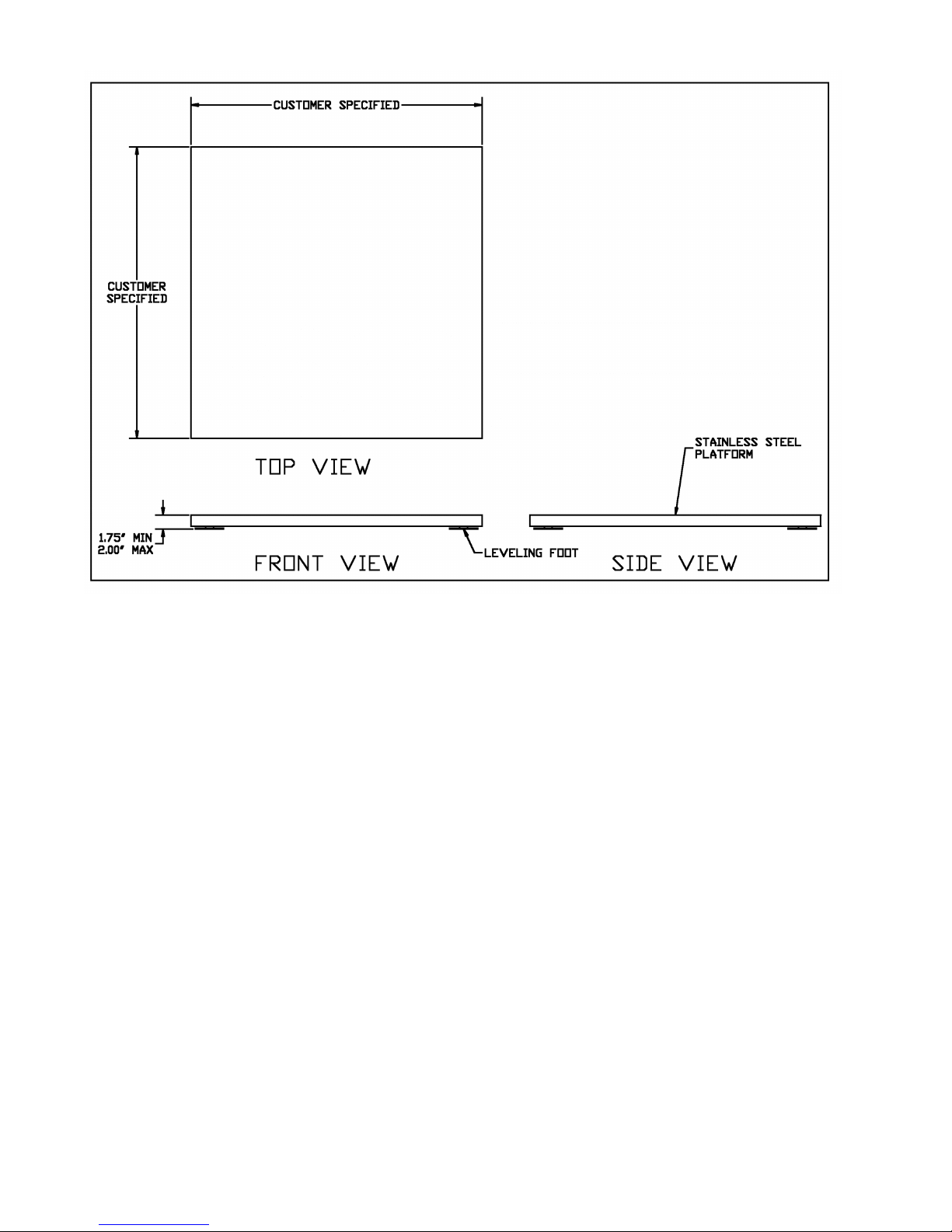
The 600E Series of Digital Baggage Scales are general-purpose scales used to weigh baggage
and freight of all sizes. They have dual remote digital displays and keypad. The displays and key-
pad are designed to be flush panel mounted to provide a stream lined finish.
This manual will cover three different styles, the Standard, Low Profile, and the Full Well versions.
Fig. 1-1
Standard Style

Page 1-2
Fig. 1-2
Full Well Style
Page 1-3
Fig. 1-3
Low Profile Style

Page 2-1
CHAPTER 2: INSTALLATION
2.1 PARTS LIST
PART
NUMBER
DESCRIPTION
600-E
QTY
600-FW
QTY
600-ELP
QTY
SC105
SCALE BASE
1
1
1
SSCOV
STAINLESS STEEL PLATFORM COVER
1
1
1
SSKICK
STAINLESS STEEL KICKPLATE
N/A
2
N/A
CMOD-1
SCALE CONTROL MODULE
1
1
1
FOOT02
2” DIA. LEVELING FEET WITH LOCKNUTS
4
4
N/A
FOOT03
3” LEVELING FOOT, CUSHION RUBBER MOUNT
N/A
N/A
4
DMOD-1
DIGITAL DISPLAY MODULES
2
2
2
KMOD-1
KEYPAD MODULE
1
1
1
DCBL-1
12’ DIGITAL DISPLAY CABLES
2
2
2
KCBL-1
12’ KEYPAD CABLE
1
1
1
WGSCR-1
WING SCREWS (LONG)
6
6
6
WGSCR-2
WING SCREWS (SHORT)
6
6
6
WDSCR-1
SCALE ANCHOR WOOD SCREWS (#12 x 4 PHL HD)
8
N/A
N/A
WDSCR-2
SCALE ANCHOR WOOD SCREWS (#8 x 1 PHL HD)
N/A
N/A
12
ABLT-1
¼X 3” CONCRETE ANCHOR BOLT
N/A
8
N/A
RCBL-1
OPTIONAL DISPLAY RIBBON CABLE ADAPTER WITH
GROUND STRAP
2
2
2
RCBL-2
OPTIONAL KEYPAD RIBBON CABLE ADAPTER WITH
GROUND STRAP
1
1
1
LBKT
OPTIONAL “L” BRACKET
1
1
1
WDSCR-2
OPTIONAL “L” BRACKET WOOD SCREWS (#8 X 1 PHL
HD)
2
2
2
AC004
120-240 VAC INPUT, 12 VDC OUTPUT (800 Ma) AC
ADAPTER
1
1
1
Table 2-1: Parts List
2.2 Scale Base Installation (600-E Standard Style)
1. Remove the stainless steel platform cover by lifting it straight up. Remove the carton of
electronics and hardware wedged between the scale structures. Open the carton and
verify that all components are present.
2. Tilt the scale base on one of its edges to access the bottom of the scale. Remove the ¼”
shipping screw from the bottom of the scale (see fig. 2-1). If this screw is not removed
the scale will not operate correctly!.
Fig. 2-1: Bottom of Scale (Shipping Screw)
Page 2-2
3. Remove the locknuts from the four (4) Leveling Feet. Thread the leveling feet all the way
into the nuts welded in all four (4) corners of the scale lower frame (see fig. 2-2). Once
the leveling feet are installed thread the locknuts back onto the top side of the leveling
feet (hand tight).
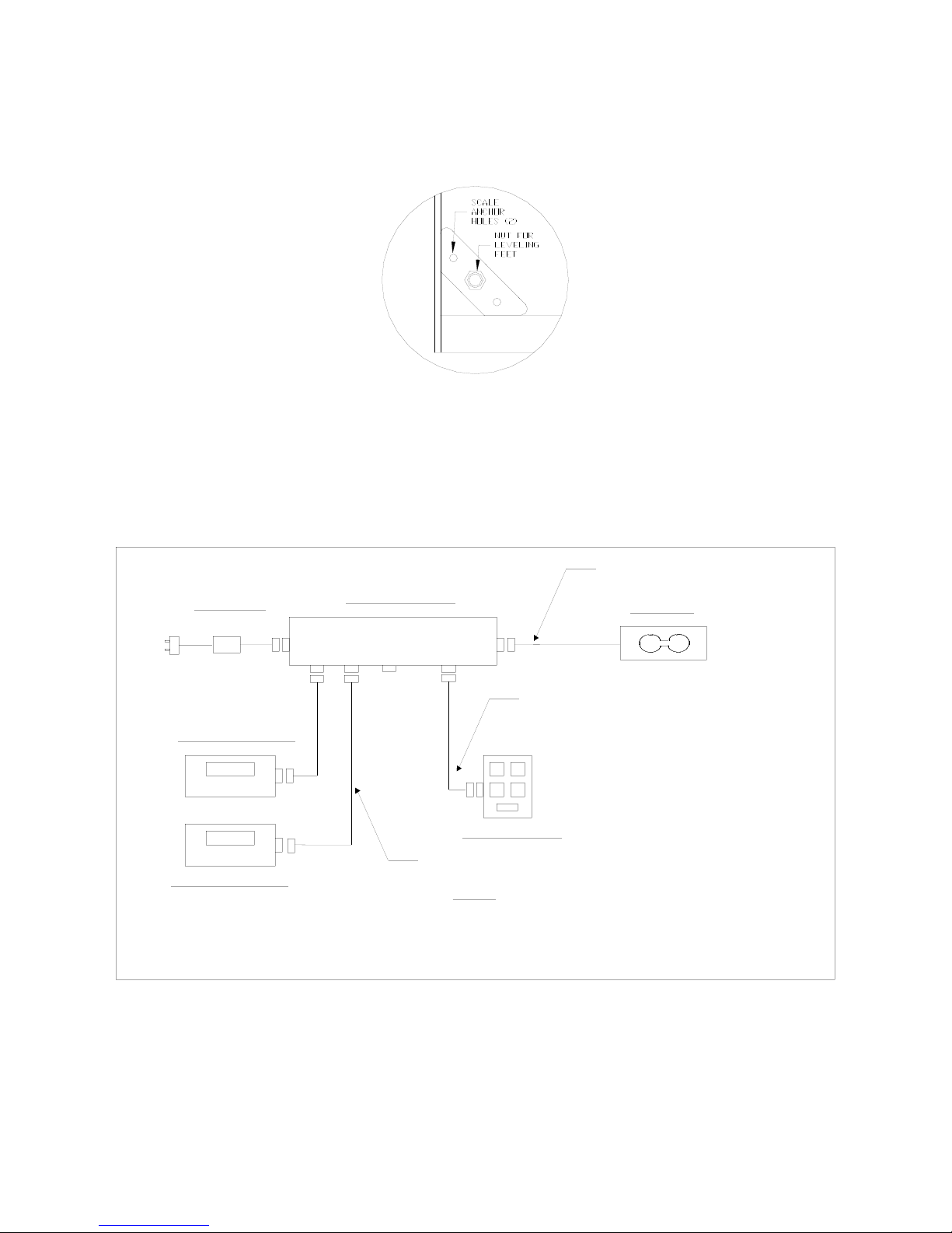
Fig. 2-2: Corner Detail
4. Before beginning installation into the counter it is recommended to perform an initial
check of the scale system. Set the scale base on the floor, level the scale and plug all
components into the control module. All the ports on the control module and cables are
clearly marked (see fig. 2-3 for System Block Diagram). Place stainless steel platter
back onto the scale. Turn the scale on with the on/off switch located on the remote
keypad.
CONTROL MODULE
TRINER MODEL 600-E BAGGAGE SCALE - SYSTEM BLOCK DIAGRAM
Power Supply
KEYPAD MODULE
DISPLAY MODULE #1
DISPLAY MODULE #2
LOAD CELL CABLE, 15 ft LONG
1. Load Cell Cable terminated by 14-pin Centronics Male.
NOTES:
2. Keypad Cable terminated both ends by 9-pin DSUB Male.
KEYPAD CABLE, 12 ft LONG
DISPLAY CABLE (x 2), 12 ft LONG
3. Display Cables terminated at control box end by 9-pin DSUB Male
and terminated at display module end by 9-pin DSUB Female.
LOAD CELL
MF
MF
F
MM
F
M
M
F
F
FM
F
To
optional
serial
cable.
120-240 VAC
12 VDC, 800 mA
Fig. 2-3: System Block Diagram
5. Remove the stainless steel top and disconnect all cables from the control module. Place
the scale base in the location provided (bag well).
6. Center the frame in the bag well opening. Adjust the leveling legs so that the scale base

Page 2-3
is approximately ½” above the opening and so that the scale is in a level position.
Tighten the locknuts on the leveling feet.
7. Use the Scale Anchor Holes at each corner (see fig. 2-2) to secure the scale base in
place with the eight (8) wood screws provided.
8. The scale base must be grounded with the lead attached to the top frame. The center
screw on an electrical outlet or a metal conduit is usually suitable. Leave some slack in
the wire. Do not pull the wire tight because it can negatively affect weighing
performance.
2.3 Scale Base Installation (600-E Full Well Style)
1. Remove the stainless steel platform cover by lifting it straight up. Remove the carton of
electronics and hardware wedged between the scale structures. Open the carton and
verify that all components are present (see table 2-1).
2. Tilt the scale base on one of its edges to access the bottom of the scale. Remove the ¼”
shipping screw from the bottom of the scale (see fig. 2-4). If this screw is not removed
the scale will not operate correctly.
Fig. 2-4: Bottom of Scale (Shipping Screw)
3. Remove the locknuts from the four (4) Leveling Feet. Thread the leveling feet all the way
into the nuts welded in all four (4) corners of the scale lower frame (see fig. 2-5). Once
the leveling feet are installed thread the locknuts back onto the top side of the leveling
feet (hand tight).
Fig. 2-5: Corner Detail
4. Before beginning installation into the counter it is recommended to perform an initial
check of the scale system. Set the scale base on the floor, level the scale and plug all
components into the control module. All the ports on the control module and cables are
clearly marked (see fig. 2-3 for System Block Diagram). Place stainless steel platter

Page 2-4
back onto the scale. Turn the scale on with the on/off switch located on the remote
keypad.
5. Remove the stainless steel top and disconnect all cables from the control module. Place
the scale base in the location provided (between ticket counters).
6. Center the frame in the opening. Adjust the leveling legs so that the scale base is in a
level position. Tighten the locknuts on the leveling feet.
7. Use the Scale Anchor Holes at each side of the lower frame (see fig. 2-5) to secure the
scale base in place with the eight (8) anchor bolts provided.
8. Attach the kick plates to the front and rear side of the lower frame. The kick plates attach
with Velcro so that they can be easily positioned and compensate for varying height and
level conditions.
9. The scale base must be grounded with the lead attached to the top frame. The center
screw on an electrical outlet or a metal conduit is usually suitable. Leave some slack in
the wire. Do not pull the wire tight because it can negatively affect weighing
performance.
2.4 Scale Base Installation (600-E Low Profile Style)
1. Remove the stainless steel platform cover by lifting it straight up. Remove the carton(s)
of electronics and verify that all components are present (see table 2-1).
2. Locate the four (4) Leveling Feet. Thread the leveling feet all the way into the threaded
load cell holes in all four (4) corners of the scale frame (see fig. 2-6).
Fig. 2-6: Corner Detail
3. Before beginning installation into the counter it is recommended to perform an initial
check of the scale system. Set the scale base on the floor, level the scale and plug all
components into the control module. All the ports on the control module and cables are
clearly marked (see fig. 2-3 for System Block Diagram). Place stainless steel platter
back onto the scale. Turn the scale on with the on/off switch located on the remote
keypad.
4. Remove the stainless steel top and disconnect all cables from the control module. Place

Page 2-5
the scale base in the location provided (bag well).
5. Center the frame in the opening. Adjust the leveling legs so that the scale base is in a
level position. Make sure there is equal pressure on all four leveling feet.
6. Use the Scale Anchor Holes at each corner (see fig. 2-2) to secure the scale base in
place with the wood screws provided.
7. The scale base must be grounded with the lead attached to the top frame. The center
screw on an electrical outlet or a metal conduit is usually suitable. Leave some slack in
the wire. Do not pull the wire tight because it can negatively affect weighing
performance.
2.5 Digital Display and Keypad Installation
1. Refer to Fig. 2-7 below to cut the holes and mount the dual digital display modules into
the counter.
Note: Counter cut-outs to be located and cut by the customer or contractor unless
otherwise specified.
Fig. 2-7: Display Cut Out Detail

Page 2-6
Fig. 2-8: Display Cable Detail
Page 2-7
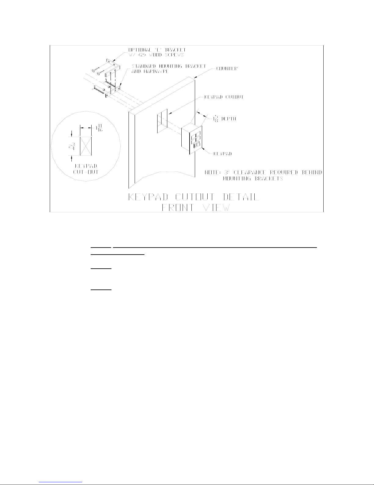
Fig. 2-9: Keypad Cut Out Detail
2. Refer to Fig. 2-9 to cut the holes and mount the keypad module into the counter.
Note 1: Counter cut-outs to be located and cut by the customer or contractor unless
otherwise specified.
Note 2: An optional “L” Bracket is included for installations where the flush panel mount
is not convenient. The “L” bracket is used for under/side counter installations.
Note 3: Locate the remote switch module so that it is convenient
to the ticket agent and not accessible to the passenger.

Page 2-8
Fig. 2-10: Keypad Cable Detail
3. Connect the display cables from the control module to each remote display (fig. 2-8).
Note: Use option “A” unless there are space constraints.
4. Connect the keypad cable from the control module to the keypad module (fig. 2-10).
Note: Use option “A” unless there are space constraints.
5. Connect one end of the AC adapter to the control module and the other end into a 120-
240 VAC grounded electrical outlet.
6. Once all connections are made, place the stainless cover back on top of the scale.
7. Turn the scale on by using the on/off switch located on the remote switch panel.
8. Test scale for accuracy and proper operation.
Refer to Chapter 7 on page 7-1 for information on General Scale Operation.

Page 2-9
2.6 LOADCELL CONNECTIONS
Note: The scale system is pre-wired the figures below are for reference only.
Color Wire Name
RED +Excitation
BLK - Excitation
GRN +Signal
WHT - Signal
Figure 2-11: Color Codes for Shielded Load Cell Cable
Pin Nos. Pin Name
1/8 +Excitation
3/10 - Excitation
5/12 +Signal
7/14 - Signal
715 3
14 12 10 8
Figure 2-12: Pin assignments for the Load Cell Port
Figure 2-13: Pin assignments
On Summing Card –Low Profile Style Only
2.7 CONNECTING THE SERIAL PRINTER, REMOTE DISPLAY OR COMPUTER
The 600E Digital Baggage Scale comes standard with one full duplex RS-232 serial port,
designed for connection to either a PC or a serial printer. The same port may be also used
as a simplex, RS-232 port designed for connection to a remote display.
Figure 2-4 shows the serial port pinout. Refer to Appendix B for some suggested cable
diagrams. (A 9-pin pin Male D-type connector is required).
1. Plug the serial printer, remote display or computer communication cable (not included)
directly into the DSUB9 serial port connector.
Pin No. Pin Name
2Receive Data
3Transmit Data
Signal Level
RS-232
RS-232
5Signal Ground RS-232
2
3
5
Front View

Page 2-10
Figure 2-14: Pin assignments for the DSUB9 serial port connector
2.8 CONNECTING THE POWER SUPPLY
1. The scale ships standard with an external AC to DC adapter. Simply plug the AC
adapter into the control module’s DC Power Jack first, and then plug into a standard wall
outlet (120-240 VAC). Make sure that the AC voltage appearing at the wall outlet
matches the input voltages marked on the AC adapter.

Page 3-1
CHAPTER 3: CONFIGURATION
3.1 CONFIGURATION OVERVIEW
Note: Your scale has been configured at the factory. Do not
attempt to enter the Setup Menu unless you are a trained
scale technician.
The scale contains two main setup menus: The Setup (“F”) menu which configures the scale to
your weigh platform and the User (“A”) menu which configures the serial communication port and
enables some user options. The Setup and User menus consist of several menu selections, each with its
own sub-menu of choices.
To set up the scale, you must first enter the appropriate menu mode. Once there, four of the remote switch
panel keys become directional navigators to move around in the menus, and one key is used to save or SET
the selections.
3.2 SETUP (“F”) MENU
3.2.1 ENTERING THE SETUP MENU
1. Power off the scale by unplugging the power source.
2. On the side of the control box, move the Setup/Calibration Switch to the opposite
position.
3. Power on the scale by plugging in the power source. The scale shows ” F 1” to indicate
that you are in Setup Menu mode.
3.2.2 NAVIGATING IN THE SETUP MENU
Use the directional keys shown in Figure 3-1 to move around in the Setup Menu Chart
shown in Figure 3-2 on the following page.
1. To move to a new “F” heading, use the PRINT (left) or LB/KG (right) key to move right
or left in the Setup Menu Chart.
2. To move to the selection level, press the ZERO (down) key once. The current saved
selection is shown.
3. To view the available selections for the current “F” heading, use the PRINT (left) or
LB/KG (right) key to move through the selection field.
4. To save a new selection, press the ACCU (Set) key .To exit without saving, press the
ZERO (up) key to return to the current “F” heading.
5. Repeat Steps 1 through 4 until the Setup Menu is programmed.

Page 3-2
KG
LB
ZERO
O
I
PRINT
ACCU SET
Figure 3-1: Setup Menu Key Assignments
F1
Grads
F2
Span Gn.
F4
Zero Range
F5
Mot. Band
F6
Dig. Filter
F7
Ovld. Limit
25 50 75 100 150 200 1 2 4 8
100% 1.9%
1d 3d 5d 10d
F8
Calib. Unit
F9
Dsp. Div.
lb kg
500 1000 1500 2000 2500 3000 4000 5000 6000 8000 10000 12000 20000 30000 40000 50000
0.5d 1d 3d0d 5d
F3
Zero Band
0d 2% 1d 9d
1 2 5
F10
Dec. Pt.
F17
Span Calib.
Press ZERO
key to begin
F18
Cal. View
Press ZERO
key to begin
F19
Key-in Zero
Press ZERO
key to begin
F20
Key-in Span
Press ZERO
key to begin
0 0.0 0.00 0.000 0.0000 00
F16
Zero Calib.
Press ZERO
key to begin
Figure 3-2: Setup Menu Chart
3.2.3 NOTES ON THE SETUP MENU
1. There is an F21 sub-menu present that is used to set all parameters to factory defaults.
2. Detailed descriptions of the setup menu parameters can be found in Chapter 4 of this
manual.
3. The User (“A”) menu sub-menus appear when scrolling left or right from the “F” menu.
3.2.4 EXITING THE SETUP MENU
1. Power off the scale by unplugging the power source.
2. On the back cover, move the Setup/Calibration Switch back to its original position.
3. Power on the scale by plugging in the power source. The display will go through a digit
check, then settle into Normal Operating mode. All front panel keys will now return to their
normal mode of operation.
Table of contents
Other Triner Scale Scale manuals

Triner Scale
Triner Scale 1200g High Precision Scale User manual

Triner Scale
Triner Scale 7600 User manual

Triner Scale
Triner Scale TS-70MC User manual

Triner Scale
Triner Scale TS-PFS User manual

Triner Scale
Triner Scale TP-10 User manual

Triner Scale
Triner Scale TSM Series User manual

Triner Scale
Triner Scale TS60-1010 User manual

Triner Scale
Triner Scale TSM5-28-LS User manual

Triner Scale
Triner Scale 7600E User manual

Triner Scale
Triner Scale TS-70PX Installation manual


