Trinity Highway INGAL SS180 M User manual
PN
626198
Revision
B March 2020
SS180
SS180
M
Product Description Assembly Manual
TRINITY
HIGHWAY
Ahead
of the
Curve
®

trinityhighway.com
1
Revision ANovember 2019
SS180®
M
The SS180®MTruck Mounted Attenuator (“TMA”) has been tested pursuant to American
Association of State Highway and Transportation Officials (“AASHTO”) Manual for Assessing
Safety Hardware(“MASH”) specifications.
Product
Description
Assembly
Manual
2525 N. Stemmons
Freeway
Dallas, Texas
75207
Warning:The local distributors, owners, contractors, lessors, and lessees
are RESPONSIBLE fortheassembly,maintenance,andrepair of the SS180®
M. Failure to fulfill these RESPONSIBILITIES withrespect to the
assembly, maintenance, and repair of the SS180®Mcouldresult in
serious injury or death.
Important: These instructions are for standard assembly specified by the
appropriate highway authority. In the event the specified system assembly,
maintenance, or repair would require adeviation from standard assembly
parameters, contact aTrinity Highway representative.
This manual must be available to the worker overseeing and/or assembling the product at
all times. For additional copies, contact Ingal Civil Products directly at 1800-803-795 or visit
www.ingalcivil.com.au.
The instructions contained in this manual supersede all previous information and manuals. All
information, illustrations, and specifications in this manual are based on the latest SS180®M
information available to Trinity Highway at the time of printing. We reserve the right to make
changes at any time. Please contact Ingal Civil Products to confirm that you are referring to the
most current instructions.
Part No.
626198
©2019 Trinity Highway Products, LLC

trinityhighway.com
2
Revision ANovember 2019
Table of Contents
Customer Service
Contacts.........................................................................................................
3
Important Introductory
Notes
...................................................................................................... 3
System
Overview
........................................................................................................................ 4
Safety
Symbols
........................................................................................................................... 4
Safety Rules for Assembly......................................................................................................... 4
Limitations and
Warnings
...........................................................................................................
..
5
Know Your SS180®MSystem ................................................................................................... 6
Assembly
...................................................................................................................................11
Recommended Tools ..........................................................................................................11
Preparation
..........................................................................................................................12
Operation Instructions.............................................................................................................. 20
Folding and Unfolding the
System.......................................................................................
20
Maintenance
..............................................................................................................................21
Routine
Maintenance...........................................................................................................
21
Detaching and Attaching the System ..................................................................................22
Lubrication
...........................................................................................................................24
Technical
Specifications
......................................................................................................
25
Repair
Instructions
.....................................................................................................................26
Post
Impact
..........................................................................................................................26
TroubleshootingGuide..............................................................................................................28
Hydraulic
Fluid
.....................................................................................................................29
Hydraulic System Check .....................................................................................................30
Pressure Relief
Valve
..........................................................................................................
32
CounterbalanceValve.........................................................................................................33
Hydraulic Cylinder ...............................................................................................................34
Hydraulic System Priming ...................................................................................................35
Reservoir.............................................................................................................................35
Electrical
Problems
..............................................................................................................36
TroubleshootingDecision Trees and System
Drawings............................................................
.
38
SS180®M............................................................................................................................40
Support Frame
Assembly
....................................................................................................41
Cartridge A..........................................................................................................................44
Cartridge B..........................................................................................................................45
Miscellaneous Part
Assembly..............................................................................................
46
Impact Face Assembly........................................................................................................47
Hydraulic Control Assembly ................................................................................................48
Hydraulic Cylinder
Assembly
...............................................................................................51
Pump
Assembly
...................................................................................................................52
Electrical Box,
Hydraulic
......................................................................................................53
LED Lighting Assembly .......................................................................................................57
Underride Assembly............................................................................................................60
Attachment
Assembly
..........................................................................................................61
trinityhighway.com
3
Revision ANovember 2019
Customer Service Contacts
Trinity Highway is committed to the highest level of customer service. Feedback regarding the
SS180®Msystem, its assembly procedures, supporting documentation, and performance is
always welcome. Additional information can be obtained from the contact information below:
TrinityHighway:
Telephone: (888) 323-6374 (USA)
+1 (214) 589-8140 (International)
Contact:
TrinityHighway.com/Contact
Website
trinityhighway.com
Important Introductory Notes
Proper assembly, deployment and future maintenance of the SS180®Mare critical to achieve
tested performance under accepted MASH criteria. Take the time to review this manual thoroughly
before performing all necessary work. These instructions should be read in their entirety and
understood before assembling the TMA. These instructions are to be used only in conjunction with
the assembly of the SS180®Msystem and are for standard assemblies only as specified by the
applicable highway authority.
In the event your system assembly requires or involves deviation from standard parameters or,
duringtheassemblyprocessaquestionarises,pleasecontact Trinity Highway customer service.
These instructions are intended for an individual who is qualified to both read and accurately
interpret them as written. They are intended for the individual who is experienced and skilled in the
assembly of highway products which are specified and selected by the highway authority.
If additional information is required, please contact Trinity Highway Customer Service. If there are
deviations, alterations, or departures from the assemblyprotocolspecifiedin thismanual,the
SS180®Mmany not perform as tested.
Important: It is the responsibility of the installer to maintain asafe work area
including the use of standard work zone safety equipment &PPE: gloves, safety-
toe shoes, and eye /ear protection.
Important: DO NOT use any component part that has not been specificallycrash
tested and/or approved for this system during assembly or repair.

trinityhighway.com
4
Revision ANovember 2019
System Overview
The SS180®Msystem has shown to reduce the risk of injury to passengers of an errant vehicle
and to the driver of the truck to which the system is attached when the system is impacted within
the applicable MASH criteria. The system mounts on the rear of atruck and may be used in
stationary applications (e.g. as atruck block in awork zone) and mobile operations (e.g. striping,
sweeping, plowing, etc.).
Safety Symbols
This section describes safety symbols that may appear in the SS180®Mmanual. Read this
manual for complete safety, assembly, operating, maintenance, repair, and service information.
Symbol
Meaning
SafetyAlertSymbol:Indicates Danger, Warning, or Caution. Failure to read
and follow the Danger, Warning, Caution, or Important statements could result in
serious injury or death to workers and bystanders.
Warning: Read safety instructions thoroughly and follow the assembly directions
and suggested safe practices before assembling, maintaining, or repairing the
SS180®M. Failure to follow this warning can result in serious injury or death to the
worker and/or bystanders.
Important: Please keep up-to-date instructions for later use and reference by
anyone involved with this product.
Safety Rules for Assembly
*Important Safety Instructions *
This manual must be kept in alocation where it is readily available to persons who assemble,
maintain, or repair the SS180®M. Additional copies of this manual are available from Trinity
Highway by calling (888) 323-6374 or contact us using TrinityHighway.com/Contact.Please
contact Trinity Highway if you have any questions concerningthe information in this manual.
Important: It is the responsibility of the installer to use proper safety precautions
when operating power equipment, mixing chemicals, and when moving heavy
equipment or SS180®Mcomponents.Theinstalleris responsibleforproperuse
of hand, eye, foot, and back protection.
Warning: Safety measures incorporating appropriate traffic control devices
specifiedby thehighwayauthoritymustbe usedto protectallpersonnelwhilethe
TMA is in use. The traffic control plan established by the highway authority must
always be observed when utilizing this product.

trinityhighway.com
5
Revision ANovember 2019
Limitations and Warnings
Trinity Highway, in compliance with MASH “Recommended Procedures for the Safety
Performance of Highway Safety Features”, contracts with FHWA approved testing facilities to
perform crash tests, evaluation of tests, and submittal of results to the FHWA for review.
The SS180®Mwas tested to meet the impact criteria, requirements, and guidelines of MASH.
These tests, specificallyset forth by the FHWA, evaluate product performanceby simulating those
impacts outlined by MASH involving atypical range of vehicles on our roadways, from lightweight
cars (approx. 2420 lb. [1100kg]) to full size pickup trucks (approx. 5000 lb. [2270 kg]) as specified
by the FHWA. Aproduct can be certified for multiple Test Levels. The SS180®Mis certified to the
Test Level as shown below:
Test Level 3: 62 mph [100 km/h]
These FHWA directed tests are not intended to represent the performance of systems when
impactedby every vehicletype or everyimpactconditionexistingon theroadway. This
system is tested only to the test matrix criteria of MASH as approved by the FHWA.
Trinity Highway expressly disclaims any warranty or liability for injury or damage to persons or
property resulting from any impact, collision or harmful contact with products, other vehicles, or
nearby hazards or objects by any vehicle, object or person, whether or not the products were
assembled in consultation with Trinity Highway or by third parties.
The SS180®Mis intended to be assembled, delineated, and maintained within specific state and
federal guidelines.It is important for the highway authority specifying the use of ahighway product
to select the most appropriate product configuration for its sitespecifications. The customer should
be careful to properly select, assemble, and maintain the product. Careful evaluation of the site
lay out, vehicle population type; speed, traffic direction, and visibility are some of the elements that
require evaluation in the selection of ahighway product.
After an impact occurs, the debris from the impact should be removed from the area immediately
and the product should be evaluated and restored to its original specified condition or replaced
as soonas possible.Allcomponentsandassembliesshould be inspected andanypartsthatare
damaged should be replaced with original Trinity Highway replacement parts. Contact the
Customer Service Department prior to repair if you have any questions (p. 3).
Warning: It is the responsibility of the installer to ensure that the SS180®Mand
delineation used meet all federal, state, specifying agency, and local specifications.
Warning: It is the responsibility of the installer to ensure that your assembly
meets all appropriate Manual on Uniform Traffic Control Devices (MUTCD) and
localstandards.
Host Vehicle Tare Weights should be between 6150kg and 11,000kg.
Warning: Roll-ahead distance is 6.4m. Plan your TMA deployment accordingly.

trinityhighway.com
6
Revision ANovember 2019
Know Your SS180®M System
For the safety of the operator, the operator shall stand at the rear of the truck, on the curb side,
(Figure 2). When tilting the TMA, care shall be taken to stay clear of all moving parts.
TYPE B CARTRIDGE TYPE A CARTRIDGE
SOCKET HITCH UNDERRIDE
SUPPORT STRUCTURE
Figure 1
STAND HERE
(FOR
CONTROLS ON
RIGHT
SIDE OF
TRUCK)
CONTROLS LOCATED
ON
EITHER SIDE OF
TRUCK
CONTROLS RHS
CARTRIDGE BCARTRIDGE A
TRUCK
STAND HERE
(FOR
CONTROLS ON LEFT
S
I
DE
OF TRUCK)
CONTROLS
LOCATED ON
EITHER
SIDE OF
TRUCK
CONTROLS LHS
Figure 2
trinityhighway.com
7
Revision ANovember 2019
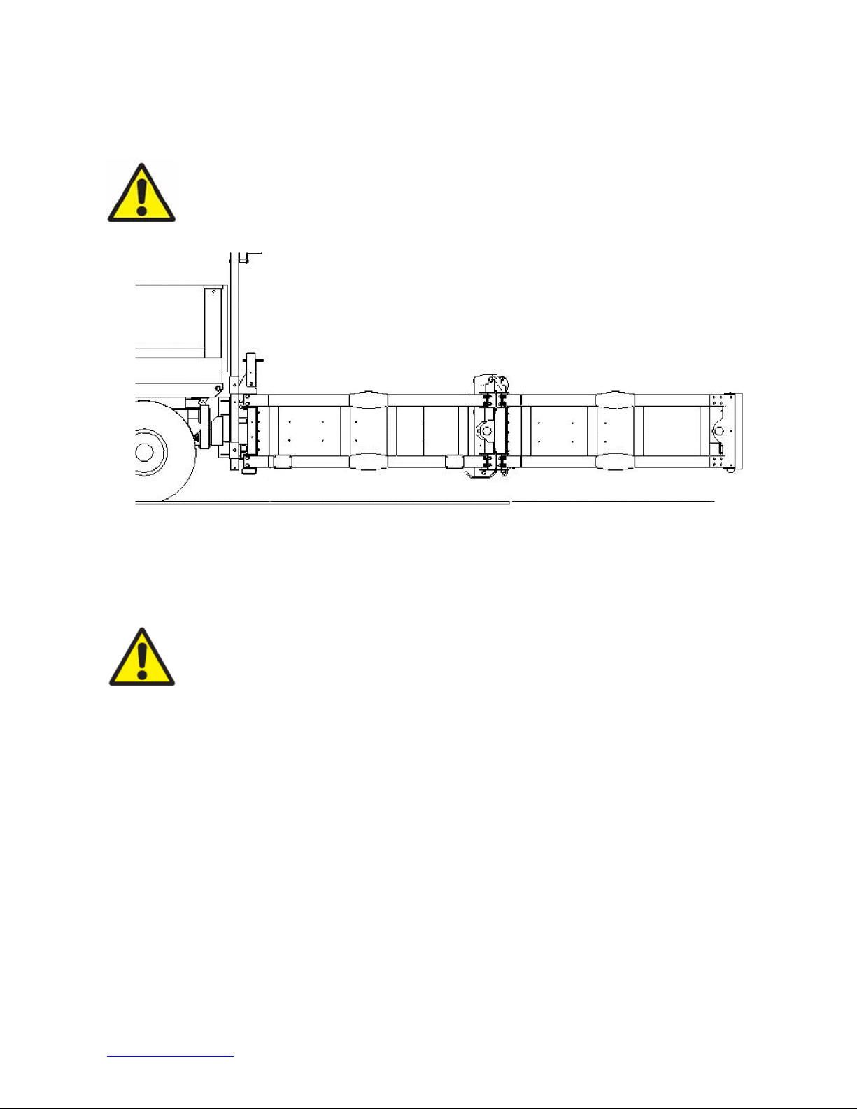
1. TheSS180®Mshallbe rigidlyfastened to thetruck.In thehorizontalposition,thebottom
of the TMA shall be 11" to 13" [280 to 330 mm] from the ground to the bottom of the Rear
Impact Face (Figure 3).
Warning: TheSS180®Mcan only absorb the energy of an impacting vehicle
when in the unfolded position.
Figure
3
↑
12” ±1” [305 mm ±25 mm]
↓
2. Jacksshall be usedto supporttheSS180®Mwhen it is detached from the truck. The
Jacks must be stored while the TMA is attached to the truck.
Important: The SS180®Mmust be deployedin the unfoldedpositionat all times
while operating as either aBarrier Vehicle or Shadow Vehicle.
The SS180®Mcan be in the "unfolded" position when traveling short distances at low speed
(not greater than 40 km/h).
The SS180®Mmust be in the "folded" position whentravelinglongdistancesat ahigh
speed(greater than 40 km/h).

trinityhighway.com
8
Revision ANovember 2019
3. The SS180®Mis intended to support its own weight and dissipate the kinetic energy of
errant vehicles per MASH criteria. Do not drag the TMA or place anything on its top or
damage will result. Do not sit, stand, or lean on any part of the TMA (Figures 4&5).
Figure
4
Figure
5
4. Before raising or lowering the TMA, the operator shall be fully trained in its proper
operation. All operators are required to fully understand the contents of this manual prior
to operating the system. The operator should never stand under the TMA while it is being
raised or lowered.
5. Folding the TMA provides the best maneuverability and driving characteristics. The TMA
shall be inits foldedtransportposition while travellingbetween deployment locations.Refer
to local agency policies as required for additional guidance. Unfold the system before
entering ajob site or beginning shadow vehicle operations. The support vehicle must be
fully stopped before TMA folding and unfolding.
6. All persons shall stand clear before folding or unfolding the TMA. The system must be
stopped in full folded position before allowing anyone directly behind the folded system.

trinityhighway.com
9
Revision ANovember 2019
7. Ballast and other heavy objects MUST BE ADEQUATELY ANCHORED to the truck to
prevent shifting during an impact (Figure 6). The force exerted on the tie-down straps could
be 20 times the weight of the ballast.
Figure
6
8. The agency responsible for the truck shall inspect it for adequate operator safety
equipment (e.g., seat belts, head rests, etc.)
9. The SS180®Mcan only be mounted to trucks weighing between 6,120 -11,340
kg.
10. Make sure that the performance and safety of the TMA is not impaired by damage or
corrosion.
Warning:This TMA is intended to be used as an impact attenuator on the rear
of trucks weighing between 6,120 -11,340 kg. TheTMAshallnotbe used for
any other purpose.
11. Regular maintenance of the TMA is critical for proper operation. Refer to the maintenance
section of this manual for additional information.
a. Regular inspection of frame members, cartridges, and fasteners is necessary to
ensure proper system performance.
b. Regular inspectionof hydraulic hoses is critical. Abroken or damagedhose will cause
the system to operate uncontrollably.
c. Keep electrical connections at the Pump Motor/Solenoid clean. Clean any hydraulic
spills or leakage to prevent bodily injury, fire, etc.
12. The driver shall be cautiouswhile making turns with the TMA in the unfolded position. The
TMA extends beyond the end of the truck and will swing wide while turning.
13. This system is an impact attenuator and is therefore used in high risk areas. Stay clear of
trafficwhenever possible.

trinityhighway.com
10
Revision ANovember 2019
14. The Hydraulic Assembly was designed to fold and unfold the TMA. Any other use may be
hazardous to people or equipment.
a. Do not use the system to push aload.
b. Do not use the raised end of the system to support any load.
c. Do not use any part of the TMA for towing or hauling aload. This could cause the lift
mechanism to malfunction and permanently damage the system.
d. Do not use the TMA as aladder.
Warning: Do not leave the TMA raised, even slightly, when deployed.
BARRIER VEHICLE -Atruck on which aTMA is mounted, while positioned upstream (towards
the direction that traffic is approaching) of awork zone.
SHADOW VEHICLE -Atruck on which aTMA is mounted, which is following behind amoving
operation such as striping, spraying, etc.
THE USE OF ATMA ON THE BACK OF ATRUCK, WHEN IMPACTED WITHIN THE
APPLICABLE MASH CRITERIA, HAS BEEN SHOWN TO:
Reduce the severity of the impact
Help protect the occupants of the impacting vehicle
Help protect the barrier or shadow vehicle occupants
Help reduce damage to the barrier or shadow vehicle
HAS NOT BEEN SHOWN TO:
Affect the skid (roll ahead) distance of an impacted truck
CONTROLLING SKID DISTANCE (ROLL AHEAD):
• Skid distance is significantly increased and is less predictable for lightweight shadow
vehicles.
• Skid distance is reduced and is more consistent when heavier shadow vehicles are used.
• Required Truck +TMA weight: 7,030 kg] up to 12,250 kg.

trinityhighway.com
11
Revision ANovember 2019
Assembly
Read and understand all instructions before beginning assembly.
Theweightof thevehicleshallbe between6,120kg and11,340kg fortested performance.
Refer to the Australian Design rules – Vehicle Standards Bulletin 6 (VSB6) for the Australian
regulations regarding chassis modifications and attachments. The system may be attached to the
truck by attaching parts to the vehicle frame, using specified hardware in the VSB6. Do not weld
any TMA components to the truck frame. It is recommended the use of side fishplate to mount the
unit to the chassis (as per page 13, figure 8). The addition of the side fishplates allows for the
removal and replacement of the mounting system, if the unit was to be damaged in a TMA impact.
Use certified or professional welders to ensure durable attachment of the TMA system.
Disconnect the truck battery before any welding on truck or TMA.
The truck frame must be suitable and accessible for mounting aTMA. If there are any questions
regarding the suitability, contact the Customer Service Department for input as to your
specific application.
Shipping list
Checkthe shipping list against the actual parts.
Recommended Tools
• Welding equipment
• Cutting torch
• Hammer
• Drift pin or alignment pin (300mm long)
• Tape measure
• 1/2” drive socket wrench w/150mm extension
• 1/2” drive sockets (9/16”, 1-1/8”, 1-1/2”, 9/16” deep well)
• Open end wrenches –(9/16”, 1-1/8”, 1-1/2”)
• 300mmcrescent wrenches –(2)
• Marking implement (pencil, soap stone)
• Drill for 13/16" diameter bit
• 13/16" diameter bit and pilot drill bit for same
• Center punch
• Torque wrench -120 N-m
• Hydraulic fluid (Dexron™ III fluid only) -Shipped with system
• Floorjackor Forklift
• Work gloves and other personal protection equipment as required
• Bubble level
Important: The above list of tools is ageneral recommendation. Depending
on specific site conditions and the complexity of the assembly specified by
the appropriate highway authority, additional or fewer tools may be required.
Decisions as to what tools are needed to perform the job are entirely the
responsibility of the specifying highway authority and the authority’s
selected contractor performing the assembly of the system at the authority’s
specifiedassemblysite.

trinityhighway.com
12
Revision ANovember 2019
Preparation
1A) Assembly Must Be Performed On Level Surface
The system’s framework is very heavy.
1B) Truck Ballast
Use abubble level to verify that the truck is parked on alevel surface. The truck shall be as close
to the final driving weight as possible. If ballast must be added to achieve the minimum weight, add
it at this time. Ballast must be properly anchored to the truck to keep it in place during an impact.
Ideally, an adequately sized truck, that requires no ballast, should be used. Because the 910
kg weight of the rearward protruding TMA is supported by the back of the shadow vehicle,
care must be taken not to exceed the manufacturer's published maximum axle loads. To ensure
that the driving characteristics of the vehicle are maintained, the manufacturer’s recommended
center-of-gravityzone shall be followed completely.
2) Interference Check
Before attempting to assemble the Underride, check for interference concerns.
The TMA folds so the Impact Face is very closeto themounting location(p. 24, Figure 25).If you
are not using astandard Socket Receiver Hitch Underride skip to Step 8.
Temporarily position the Underride Socket Receiver undertruckframe as shown(p.13,Figure8)
and check for interference concerns. Interference concerns with tail lights, springs, dump bodies
(in the folded or unfolded positions), etc., shall be corrected before proceeding.
STEPS 2&3
ATTACHMENT ASSEMBLY
STEP 5&
6
SUPPORT FRAME
UNDERRIDE
SOCKET
RECEIVER
SUPPORT MOUNT
STEP 4
Figure 7
trinityhighway.com
13
Revision ANovember 2019
3) Underride Assembly
With the truck at its actual driving weight and parked on a level surface, measure the distance from
the ground to the bottom of the truck frame. A distance of 711mm ± 25 mm is required. Spacer
Tubes may be added to the bottom of the frame to achieve this height (p. 14, Figure 10).
Note: The truck’s springs may settle with the weight of the TMA, sometimes as much
as 50 mm. Adjust the height to compensate for anticipated settling.
Measure distance from the back end of the frame forward to the rear-most leaf spring hanger. Look
for any obstruction on the bottom of the frame that may interfere with the Socket Receiver. A
minimum of 305 mm is required (Underride Assembly drawing on p. 60).
It is important to check for obstructions before mounting the socket receivers. Position the Socket
Receiver at the rear end of the frame so that the 76 x 387 mm flat bar is along the outside of the
frame member and the Socket Receiver Assembly is flush with the end of frame. If spacers are
required, weld them to the Socket Receiver and lap the Spacer Splices (pieces of 10 x 51 x 103
mm flat bar) across the Socket Receiver and Spacer at the rear most location (p. 47). The top of
the Socket Receiver shall be 711mm ± 25 mm from the level ground for proper system height (p.
14, Figure 10).
Important: Welding must be performed by professional or certified welder.
All welds must be then primed and painted.
Australian chassis modification regulations may differ to that explained in this manual. It is always
recommend that you follow your local design rules when modifying the vehicle's chassis and
installing any TMA. Ensure that the vehicle and any modifications carried out meet the compliance
requirements for your region.
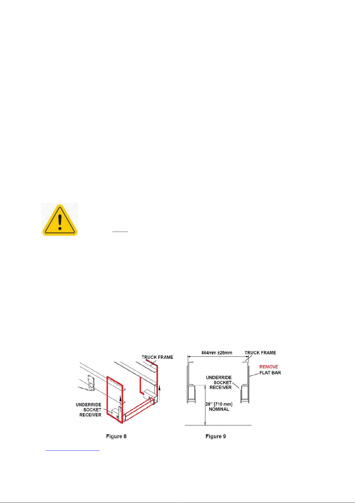
To provide addition strength to the rear of the chassis, it is recommend that the Underride Socket
Receivers have the flat mounting bar removed, then weld the Underride Socket Receivers to a large
16mm thick steel fishplate (similar as shown below in figure 8). Remember to position holes in the
fishplates for the pins to pass through the socket receiver. Then bolt the fishplates to the chassis and
if possible, also the tray sub frames. Once bolted on, install an extra cross-brace on the inside
between each Underride Socket Receiver. This will provide a rigid rear mount assembly (without
welding to the chassis), while allowing the removal and replacement of the receivers if damaged in
a TMA impact.

trinityhighway.com
14
Revision ANovember 2019
An example of modified Underride Socket Receiver mounts are shown below.They are a
suggested guide on how to install the Underride Socket Receivers without welding to the
vehicle chassis.
Installation of the Underride Socket Receivers may vary on each vehicle due
to chassis, suspension and body variations. You should allow seek the
direction of a engineer as to the best installation for your selected vehilce,
prior to beginning installation.
A
B
A
B

trinityhighway.com
15
Revision ANovember 2019
762 ±25 mm
711 ±25 mm
711 ±25 mm
Important: Left and right Underride Socket Receivers must be parallel and
level with each other.
TRUCK FRAME TRUCK FRAME
SPACER TUBES
FLUSH
WITH
FRAME
END
UNDERRIDE SOCKET
RECEIVER UNDERRIDE
SOCKET
RECEIVER
WITH SPACERS WITHOUT SPACERS
Figure 10 –Socket Hitch
Left Side
Shown
4) -Socket Hitch Assembly
Insert the Socket Hitches and pin them into place using the 1” x 6 3/4” Hitch Pins and
Retainer Pins shipped with the system.
RIGHT SOCKET
HITCH
LEFT SOCKET HITCH
HITCH &RETAINER PINS
Figure
11
B
A

trinityhighway.com
16
Revision ANovember 2019
5) Mount the Support Brackets to Socket Receivers
Mount the Support Brackets to the Socket Hitches as shown in Figure 12. Shims are used to level
the system. It is recommended that two (2) 1/4" Shims per side be used initially. This may be
adjusted once the system is assembled.
2 1/2” X 3 1/4/”
BAR WASHER
TRUCK FRAME
SOCKET
HITCH
3 1/4”X3 1/4”
BAR WASHER
SUPPORT
BRACKET
1” HEX NUT
1” LOCK WASHER
1” FLAT
WASHER
12GA
SHIM
Figure 12
1/4” SHIMS (TWO PER SIDE
RECOMMENDED AT INITIAL SETUP.
LEVEL THE TMA BY ADJUSTING
THE NUMBER OF SHIMS
1” FLAT WASHER
1X3 1/2” HEX BOLT
6) Attach the Support Frame /Backup to the Attachment Assembly
Move the system to the truck and pin the Support Frame/Backup Assembly to the Support Brackets
(Figure 13). The system is to be assembled as a whole unit. Use forklift slings to support the system.
Use the upper set of mounting holes for the attachment.
UPPER
MOUNTING
HOLES SUPPORT FRAME /
BACKUP ASSEMBLY
1-1/4 X7” HITCH PIN
Figure
13
ADD SHIMS TO LEVEL
SYSTEM (STEP 7)

trinityhighway.com
17
Revision ANovember 2019
7) Adjust the Height of the System Frame
Verify that the system frame is 305mm ±25 mm from the ground at the rear of the system.
It may
be necessary to add shims to the Socket Hitch in order to level the Frame (Figures 3 & 12).
8) Connect the Lights and Controls
Locate the female TMA Socket Connector in aconvenient location on the truck so that lifting or
lowering the TMA will not damage the electrical cable. Make sure that the electrical cord on the
TMA can reach this location.
For support vehicles with combined tail and clearancelights, connect a jumperbetweenpins 2 and
6on the backside of the male TMA plug connector (VIEW A-A and Figure 14). Connect the
7-pinplugtothesocket on thetruck.
The truck battery must be of the proper voltage. The SS180®Mis available in 12 and 24 volt
versions. Be sure the system and truck are compatible. Use standard safety practices when
attaching the battery cables. Attach positive terminal first when connecting and remove the
negative cable first when disconnecting the battery. Do not run the battery cables around sharp
corners, metal work, or in other areas that could pinch or cut the cables. Connect the battery cable
to the pump motor. Consult the Hydraulic Assembly drawing package.
Caution: For over-current protection, the positive cable lead coming off the
truck battery should be protected with a70 amp fuse or circuit breaker within
450mm of the truck battery.
The controls at the rear of the truck are mounted to bothsides of theSupportFrame.Securely
fasten cable ties to secure any loose wiring to the SS180®Mframe. Mount the cab switch box
inside the cab within easy reach of the driver and plug in the cabswitch box at the mating connector
of the TMA.
VIEW A-A
A
A
Figure
14

trinityhighway.com
18
Revision ANovember 2019
9) Check the Hydraulic System
TheHydraulic Assemblyis pre-assembledandtestedforoperationandleaksbeforeshipping.The
pump is wired as shown on the Hydraulic Assembly drawing (pp. 53-56). Before operating the
system, check to see if the reservoir has adequate fluid. The fluid level of afolded system should
beapproximately half full. Add onlyDexron™ III ATF fluid.Do notoverfill or fluid may leak out when
un-folded. Replace the cap in the fill port.
Read Operation Instructions (p.19;Folding andUnfoldingthe System). To ensure all electricaland
hydraulic lines will not be damaged, use the switch at the rear of the truck to fold and unfold the
system twice. Cycling the SS180®Mwill purge excess air from hydraulic lines and confirm its
operational status.
Important: Cycle the system using the cab switches to test controller operation.
OPERATION SWITCH
RESERVOIR CAP
APPROXIMATE FLUID LEVEL
W/SYSTEM UN-FOLDED
APPROXIMATE FLUID LEVEL
W/SYSTEM FOLDED
Figure
15
Note: Continuous operation may run down truck battery and/or damage pump.
Important: Ensure both positive and ground cables are connected directly from
pump to battery. DO NOT rely on chassis or frame for proper grounding.

trinityhighway.com
19
Revision ANovember 2019
10) Store the Jacks
The Jacks are provided to facilitate the attachment and removal of afolded SS180®Mfrom the
truck. Retrieve Jacks set aside earlier and place them in astorage location (Figure 16).
Figure
16
Important:Unbolt, remove, and store Jacks when the TMA is in service.
11) Verify the Position of the Hydraulic/Electrical Lines
Check the location of all the hydraulic and electrical lines to be sure they will not be damaged
whilefoldingandunfolding thesystem.
12) Final Check of System
Double check the height and levelness of the system.
13) Ready to Use
The SS180®Msystemis nowreadyforuse.To ensureproper andsafeoperation,allSS180®M
users shall be given operating and safety training from this manual and as specified by the owner
andlocalregulations.
Table of contents
Other Trinity Highway Control Unit manuals

Popular Control Unit manuals by other brands

Siemens
Siemens 3VA9.37-0VF10 quick start guide

Conrad
Conrad BRC36 operating instructions

Viessmann
Viessmann vitotronic 200-h Installation and service instructions

Elster
Elster Kromschroder VMF Series technical information

Elko
Elko EST3 quick start guide

Grundfos
Grundfos CIM 260 Functional profile and user manual


