Trinity Highway QuadGuard Elite M10 User manual

Revision E April 2021
Revision E April 2021

The QuadGuard
®
M10 has been tested pursuant to American Association of State Highway and
Transportation Officials (“AASHTO”) Manual for Assessing Safety Hardware (“MASH”)
specifications. The QuadGuard
®
M10 has been deemed eligible for federal-aid reimbursement on
the National Highway System by the Federal Highway Administration (“FHWA”).
Product Description
Assembly Manual
15601 Dallas Parkway
Suite 525
Addison, Texas 75001
QuadGuard®M10 610mm 24”
The information contained in this manual supersede all previous versions. The instructions,
illustrations, and specifications are based on the latest QuadGuard
®
M10 information available to
Trinity Highway at publication. We reserve the right to make changes at any time. Please visit
ingalcivil.com.au/products/road-safety-barriers/crash-cushions/quadguard-m10-mash to confirm
the latest revision.
Important:
These instructions are for standard assembly specified by the
appropriate highway authority. In the event the specified system assembly,
maintenance, or repair would require a deviation from standard assembly
parameters, contact a Ingal Civil Products representative. This system has
been deemed eligible by the FHWA for use on the national highway system under
strict criteria utilized by that agency.
QuadGuard
®
is a registered trademark of Energy Absorption Systems, Inc. Part No. 625877
© 2020 Trinity Highway Products, LLC
ingalcivil.com.au 1 Revision E April 2021
Warning:
The distributors, owners, contractors, lessors, and lessees are
RESPONSIBLE for the assembly, maintenance, and repair of the
QuadGuard
®
M10. Failure to fulfill these RESPONSIBILITIES could result
in serious injury or death.

Table of Contents
Customer Service Contacts .......................................................................................................... 3
Important Introductory Notes ........................................................................................................ 3
Safety Symbols ............................................................................................................................. 4
Safety Rules for Assembly............................................................................................................ 4
Limitations and Warnings.............................................................................................................. 5
System Overview .......................................................................................................................... 6
Inspect Shipping...................................................................................................................... 6
System Components............................................................................................................... 7
Determine Transition Type....................................................................................................11
Recommended Tools.................................................................................................................. 12
Site Preparation/Foundation ....................................................................................................... 14
Foundation/Anchoring........................................................................................................... 15
Trinity Highway Approved Adhesive Anchoring System ............................................................. 16
Vertical Anchors.................................................................................................................... 16
Anchor Assembly Cautions ................................................................................................... 17
Horizontal Anchors
........................................................................ 34
Maintenance and Repair............................................................................................................. 35
Inspection Frequency............................................................................................................ 35
Visual Drive-By Inspection .................................................................................................... 35
Walk-Up Inspection Checklist ............................................................................................... 35
Post-Impact Instructions........................................................................................................ 36
Parts Ordering Procedure & Drawings........................................................................................
................................................................................................................ 18
System Assembly ....................................................................................................................... 21
QuadGuard®M10 610mm [24”]Final Inspection Checklist
ingalcivil.com.au 2 Revision E April 2021
38
Parts List(s) & Quantities ...................................................................................................... 38
QuadGuard®M10 w/ Tension Strut Backup.................................................................. 40
TS Concrete Pad.......................................................................................................... 41
TS Concrete Pad 8” w/Rebar............................................................................................ 42
Tension Strut Backup .................................................................................................... 43
Monorail Assembly............................................................................................................. 44
Diaphragm Assembly.........................................................................................................
45
Shim Kit...................
........................................................................................................... 46
Fender Panel Assembly............................................................................................... 47
Nose Assembly................................................................................................................. 48
Safety Shape Barrier Transition.....................................................................................49
Single Slope Transition................................................................................................... 50
Vertical Barrier Transition..................................................................................................... 51
Vertical Barrier Transition, Extended.................................................................................. 52
Customer Service Contacts
Important Introductory Notes
Important:
DO NOT use any component part that has not been specifically
specified herein for the QuadGuard
®
M10 during the assembly or repair of this
system (p. 7 – 10 / 38 - 39).
Ingal Civil Products is committed to the highest level of customer service. Feedback regarding
the QuadGuard
®
M10, its assembly procedures, supporting documentation, and performance
is always welcome. Additional information can be obtained from the contact information below:
Contact Link ingalcivil.com.au/contact-us
ingalcivil.com.au 3 Revision E April 2021
Proper assembly of the QuadGuard
®
M10 is critical to
Ingal Civil Products
achieve tested performance that has been
evaluated and deemed eligible by the FHWA per AASHTO MASH criteria. These instructions
should be read and understood in their entirety before assembly. These instructions are for
standard assemblies and used in conjunction with the assembly of the QuadGuard
®
M10 as
specified by the applicable highway authority. If you need additional information, or have
questions about the QuadGuard
®
M10, please contact the highway authority that has planned
and specified this assembly and, if needed, contact Ingal Civil Products. This product must
be assembled in the location specified by the appropriate project engineers.If there are
deviations, alterations, or departures from the assembly protocol specified in this manual, the
device may not perform as tested.
A manufacturer’s drawing package will be supplied by Ingal Civil Products upon request.
Each system will be supplied with a specific drawing package unique to that system. Such
drawings take precedence over information in this manual and shall be studied thoroughly by a
qualified individual who is skilled in interpreting them before the start of any product assembly.
This product has been specified for use and has been provided to that user who has unique
knowledge of how this system is to be assembled. No person should be permitted to assist in
the assembly, maintenance, or repair of this system that does not possess the unique
knowledge described herein. These instructions are intended for an individual qualified to both
read and accurately interpret them as written. These instructions are intended only for an
individual experienced and skilled in the assembly of highway products.
Telephone 1300 446 425

Safety Symbols
This section describes the safety symbols that appear in this manual. Read the manual for
complete safety and assembly information.
Symbol Meaning
Safety Alert Symbol:
Indicates Important, Caution, Warning, or Danger. Failure
to read and follow the Important, Caution, Warning, or Danger indicators could
result in serious injury or death to workers and/or bystanders.
Warning:
Read safety instructions thoroughly and follow the assembly directions
and suggested safe practices before assembling, maintaining, or repairing the
QuadGuard
®
M10. It is the responsibility of the installer to follow the instructions
contained in this manual. Failure to comply with these warnings could result in
increased risk of serious injury of death in the event of a vehicle impact.
Important:
Please keep up-to-date instructions for later use and reference by
anyone involved in the assembly of the product.
Safety Rules for Assembly
* Important Safety Instructions *
It is the responsibility of the installer to use appropriate safety precautions when operating power
equipment, mixing chemicals, and when moving heavy equipment or QuadGuard
®
M10
components. Safety articles including but not necessarily limited to work gloves, eye protection,
safety-toe shoes, and back protection should be used.
Warning:
It is the responsibility of the installer to use all safety measures
incorporating appropriate traffic control devices specified by the highway authority.
These measures must be used to protect all personnel while at the assembly,
maintenance, or repair site.
Warning:
Failure to comply with these warnings could result in increased risk of
serious injury or death in the event of a vehicle impact with a system that has not
been accepted by the FHWA.
Warning:
Use only Trinity Highway parts on the QuadGuard
®
M10 for assembly,
maintenance, or repair. The use of component parts not specified herein is strictly
prohibited. The QuadGuard
®
M10 assembled with Trinity Highway parts has been
tested, approved, and accepted for use by the FHWA. A QuadGuard
®
M10 using
parts other than those specified herein has not been tested, approved, or accepted
for use by the FHWA. Failure to follow this warning could result in increased risk
of serious injury or death in the event of a vehicle impact.
Ingal
/crash
This manual must be kept in a location where it is readily available to persons who are skilled and
experienced in the assembly, maintenance, or repair of the QuadGuard
®
M10. Additional copies
of this manual are available from or by visiting
ingalcivil.com.au/products/road-safety-barrier uadguard-m10-mash. Please
contact Ingal Civil Products if you have any questions concerning the information in this manual
or about the QuadGuard
®
M10.
Civil Products on 1300 446 425
s -cushions/q
ingalcivil.com.au 4 Revision E April 2021
Limitations and Warnings
Pursuant to MASH “Recommended Procedures for the Safety Performance of Highway Safety
Features”, Trinity Highway contracts with FHWA approved testing facilities to perform and
evaluate crash tests to prepare a crash test results report. Trinity Highway is then able to submit
a Request for Federal Aid Reimbursement of Safety Hardware Devices to the FHWA for review.
These AASHTO directed tests are not intended to represent the performance of systems
when impacted by every vehicle type or every impact condition existing on the roadway.
This system is tested only to the test matrix criteria of MASH as approved by FHWA.
Trinity Highway expressly disclaims any warranty or liability for injury or damage to persons or
property resulting from any impact, collision or harmful contact with products, other vehicles, or
nearby hazards or objects by any vehicle, object or person, whether or not the products were
assembled in consultation with Trinity Highway or by third parties.
Warning: Do not assemble, maintain, or repair the QuadGuard®M10 until you
have read this manual thoroughly and completely understand it.
Warning: Ensure that all Danger, Warning, Caution, and Important statements
within this manual are completely followed. Failure to follow this warning could
result in serious injury or death in the event of a collision.
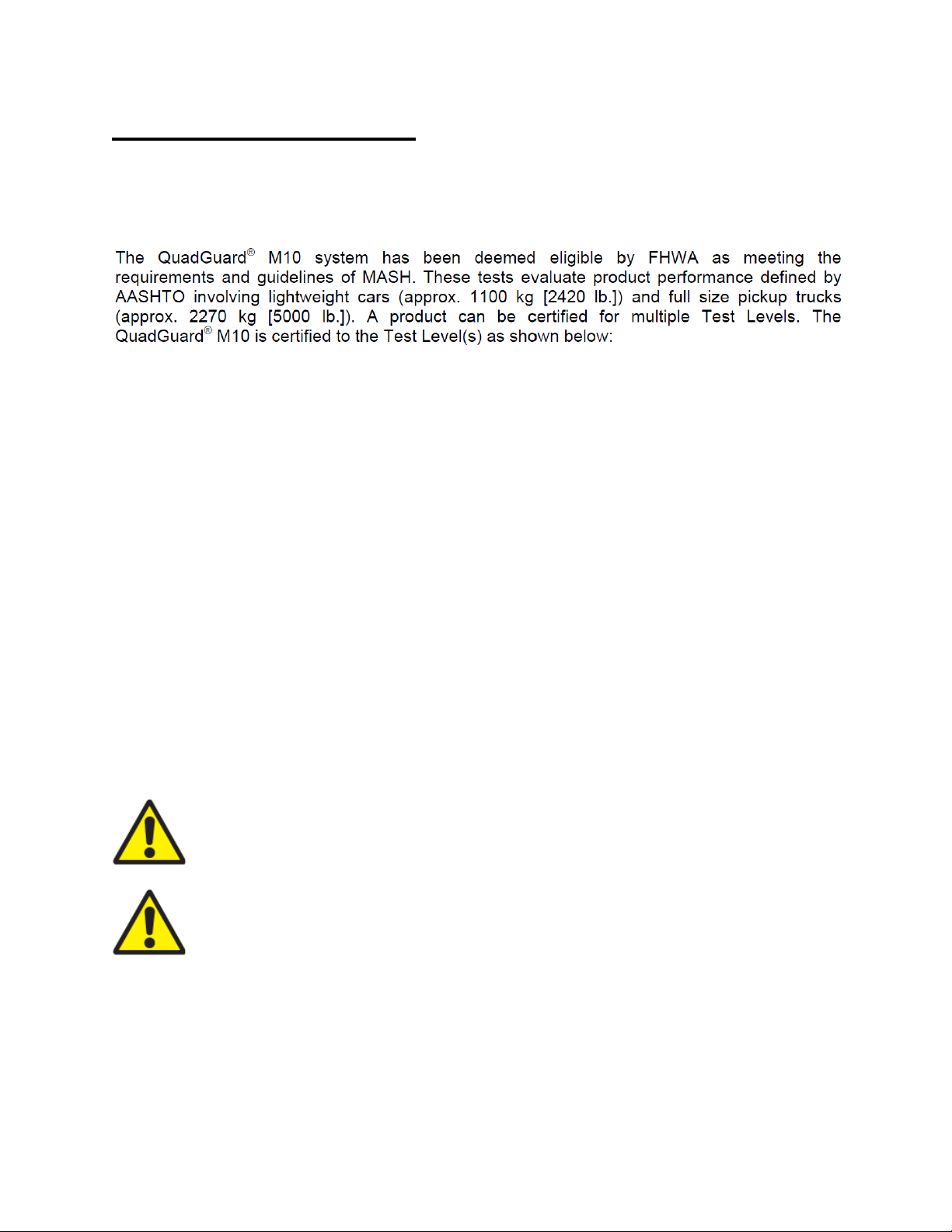
Test Level 3: 100 kph
Test Level 2: 70 kph
ingalcivil.com.au 5 Revision E April 2021
The QuadGuard®M10 is intended t
project engineer
o be assembled, delineated, and maintained within specific
state and federal guidelines. It is important for the specifying the use of a
highway product to select the most appropriate product configuration for site specifications. The
customer should be careful to properly select, assemble, and maintain the product. Careful
evaluation of site layout, traffic speed/type, direction, and visibility are some of the elements that
require evaluation by the project engineer in the selection of a highway product. For example,
curbs could cause an untested effect on an impacting vehicle.
After an impact occurs, the debris from the impact should be removed from the area immediately
and the specified highway product should be evaluated and restored to its original specified
condition or replaced as the project engineer determines as soon as possible.

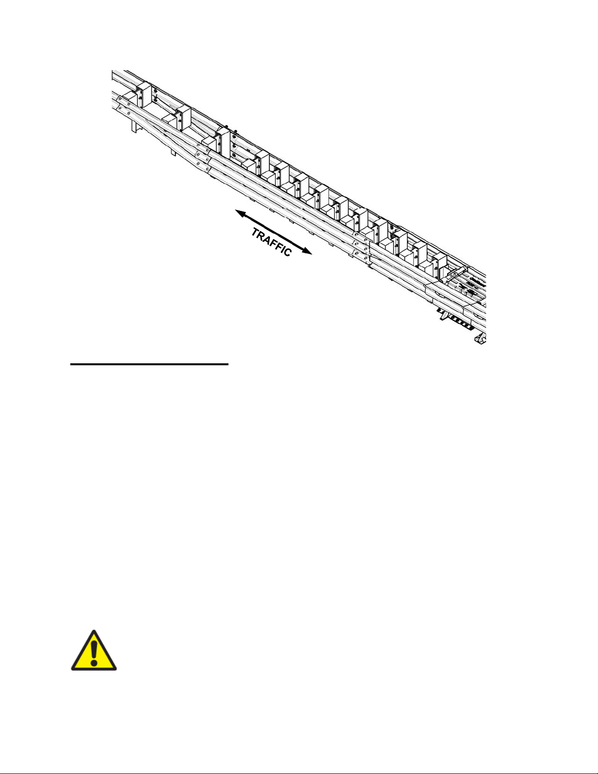
System Overview
The QuadGuard®M10 is a re-directive, non-gating crash cushion for roadside features of
24” [610 mm] or greater in width with use of approved transitions. It consists of energy-absorbing
cartridges surrounded by a framework of Quad-Beam Fender Panels.
The QuadGuard®M10 utilizes two types of cartridges in a “staged” configuration that are designed
and tested to address vehicles as defined by MASH for both lighter cars and heavier, high center-
of-gravity vehicles.
Impact Performance
Inspect Shipping
Check the received parts against the shipping list supplied with the system before deploying the
QuadGuard®M10. Make sure all parts have been received (p. 38 - 39).
Important: The Manufacturer’s Drawing Package supplied with the QuadGuard®
M10 must be used with these instructions for proper assembly and should take
precedence over these general instructions.
Warning: Do NOT modify the QuadGuard®M10 in any way.
The six (6) Bay QuadGuard®M10 has successfully passed the requirements stipulated in MASH
with both the light car and pickup trucks at speeds of up to 100 kph [62 mph] at redirection angles
up to 25 degrees.
The three (3) Bay QuadGuard®M10 has successfully passed the requirements stipulated in
MASH with both the light car and pickup trucks at speeds of up to 70 kph [44 mph] at redirection
angles up to 25 degrees.
During head-on impact testing, within MASH criteria, the QuadGuard®M10 has been shown to
telescope rearward to absorb the energy of impact. When impacted from the side, within the
applicable MASH criteria, it has been shown to redirect the vehicle back toward its original travel
path and away from the highway feature.
Important: Trinity Highway makes no recommendation whether use or
reuse of any part of the system is appropriate or acceptable following an
impact. It is the sole responsibility of the project engineer to make that
determination. It is critical that you inspect this product after assembly is
complete to make certain that the instructions provided in this manual have
been strictly followed.
ingalcivil.com.au 6 Revision E April 2021
Warning: It is the sole responsibility of the project engineer to ensure that the
QuadGuard®M10 and delineation used meet all federal, state, specifying
agency, and local specifications.
Warning: It is the sole responsibility of the project engineer to ensure that the
QuadGuard®M10 meets all appropriate Manual on Uniform Traffic Control
Devices (“MUTCD”) and local standards.
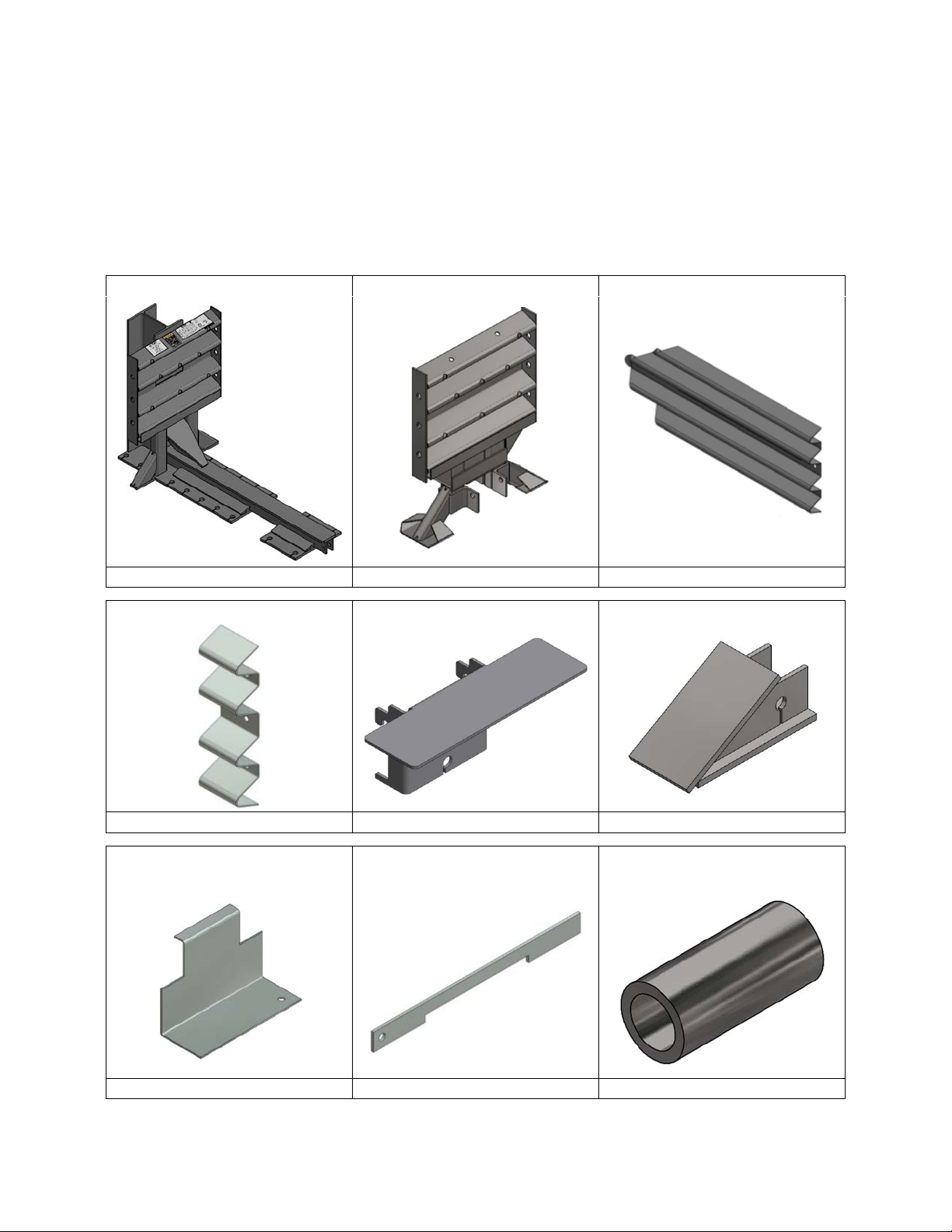
System Components
Note:
Components are not shown to scale.
Panel, Side, QG Bracket, Cartridge Support End Cap, Monorail, QG, G
Bracket, Cartridge Support
TS B/U
Locking Bar, Cartridge
Support
Pipe, 3/4” Sch 80X3
Tension Strut Backup 24” Diaphragm 24” Panel, Fender, QG
10102304 10102113 10102002
10102004 10102400 10102313
10102406 10102419 627537
ingalcivil.com.au 7 Revision E April 2021
Below is a list of system components that may be used in your particular QuadGuard®M10
configuration. Verify parts delivered and system details with the BOM (Bill of Materials) and
system drawings shipped with your system. Please call Ingal Civil Products if you have any
system questions (p. 3).
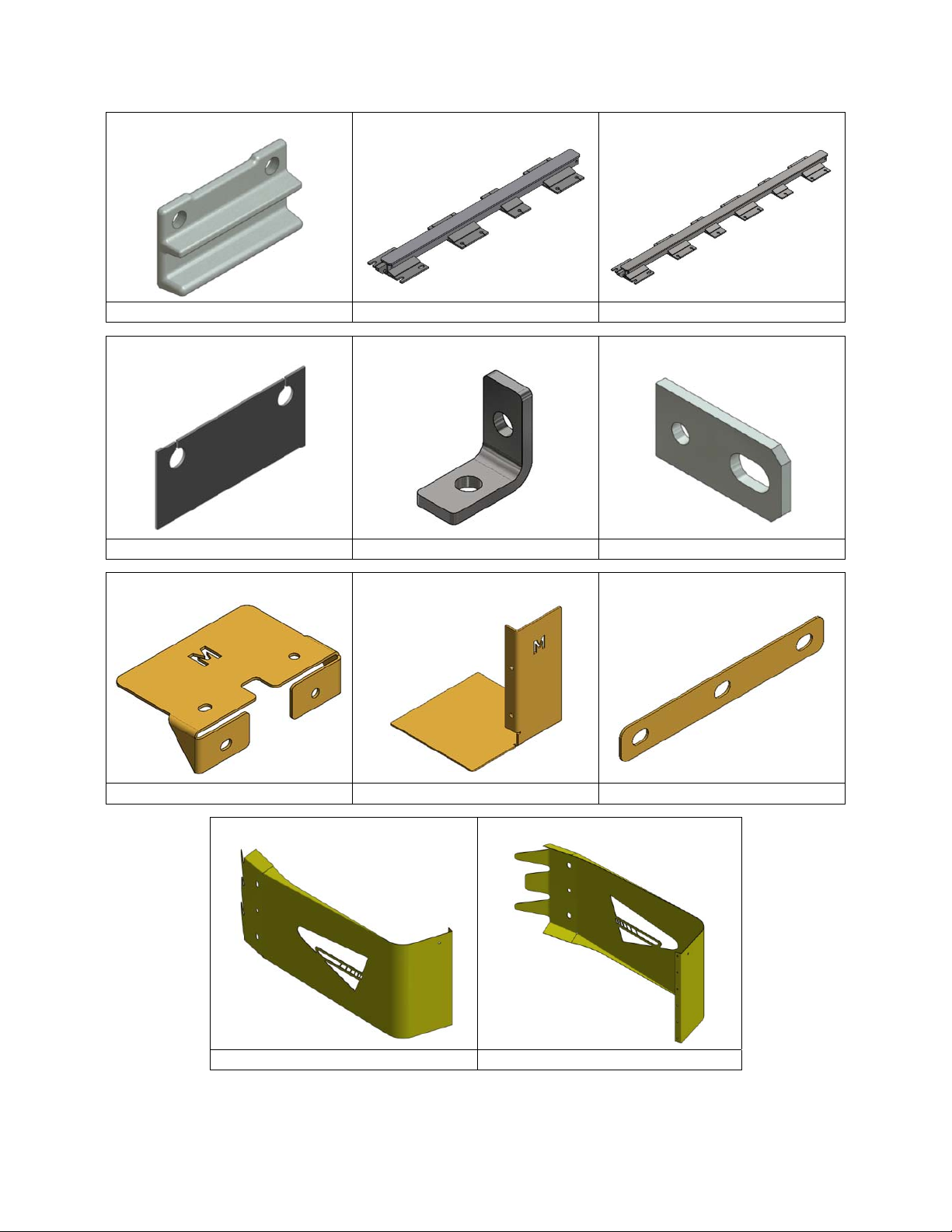
Monorail Guide Monorail, Two Bays, QG, G Monorail, Three Bays, QG, G
Shim, 12GAX3 5/8X8 Bracket, Angle, 2X1, W/Holes Bracket, Pull-Out
Nose, L, W/Logo Nose, R, W/Logo
10102534 10102311 10102312
10102906 10102213 10102411
10102211 10102212 10102210
10102202 10102204
Bracket, Cart, Hold Down Bracket, Cart Support, Nose WASHER,10GA X2X14,SLOT
ingalcivil.com.au 8 Revision E April 2021

Bolt, Hex, 1/4X3/4, G5 Bolt, Hex,3/8X1,G5 Bolt, Hex, 5/8X3 1/2, G5
Rail Bolt, 5/8X2 Bolt, Rail 5/8-11X5 Bolt, Hex, 3/4X2, G8
Nut, Hex, 1/4 Nut, Hex, 3/8 Rail Nut, Hex, 5/8
Nut, Hex, 5/8 Nut, Heavy Hex, 3/4
10102508 10103162 10102552
10102503 004441 10102462
Anchor, M20 x 165mm Gr 8.8 Anchor, M20 x 180mm, Gr 8.8 Anchor, M20 x 460mm Gr 8.8
10102549 10102547 10102911
10102515 10102516 10102501
10102502 10102504
ingalcivil.com.au 9 Revision E April 2021
10102539
M20 Structual Nut Hex Galv

Washer, Lock, 5/8 Washer, Lock, 3/4 Washer, Flat 3/8X1
Washer, Flat, 5/8X1 3/4 Washer, Fender, 3/8X2 Washer, Flat, 3/4X2
Mushroom Washer Flat Screw 5/8X5,G8 Die Spring, 5/8 X 1 1/2
Cartridge Assy, Type I Cartridge Assy, Type II Approved Adhesive
10102530 10102528 10102526
10102536 10102520 10102523
10102500 118038 10102547
ingalcivil.com.au 10 Revision E April 2021
10102903 10102904 10102902

Determine Transition Type
Note:
A proper Transition Panel or Side Panel must be used on each side of the Backup. A Side
Panel is not needed when a Transition Panel is used. The correct Panel(s) to use will depend on
the direction of traffic and what type of barrier or road feature the QuadGuard
®
M10 is shielding.
Contact the Customer Service Department prior to deployment if you have any questions (p. 3).
Figure 1
No Transition
(Unidirectional only)
Figure 3
Single Slope 6” Offset
Figure 2
Safety Shape 4” Offset
Figure 4
End Shoe
Figure 5
Extended End Shoe
ingalcivil.com.au
11 Revision E April 2021
Figure 6
Quad to Thrie-Beam
Recommended Tools
Documentation
Manufacturer’s Assembly Manual
Manufacturer’s Drawing Package
Personal Protective equipment
Eye Protection
Gloves
Safety-toe Shoes
Protective Clothing
Reflective Vest
Cutting equipment
Important:
Trinity Highway recommends using double-fluted drill bits to achieve
optimum tensile strength when applying an approved adhesive anchoring system
(p. 15).
Rotary Hammer Drill
Rebar cutting bit
Concrete drill bits – 22 mm] (Double-Fluted)
Grinder, Hacksaw or Torch (optional)
ingalcivil.com.au 12 Revision E April 2021
Figure 7
Quad to W-Beam

Hammers
Sledgehammer
Standard
Heavy duty 1/2” drive impact wrench
1/2" drive sockets: 7/16”, 9/16", 15/16", 1 1/16”, 1 1/8", 1 1/4"
1/2" drive Deep well sockets: 15/16", 1 1/4”
1/2" drive Ratchet and attachments
1/2" drive Breaker bar – 24” long
1/2" drive Torque wrench: 200 ft-lb
Combination wrench(s): 7/16”,9/16”, 15/16”, 1 1/8”
Hex Key (Allen) wrench: 3/8”
Miscellaneous
Traffic control equipment
Lifting and moving equipment (A lifting device is preferred although a forklift can be used.)
Minimum 5,000 lb. capacity required.
Air Compressor (100 psi minimum) and Generator (5 kW)
Long pry bar
Drift pin 300 mm
Center
punch
Tape measure 7.5m [25’]
hammer
Wrenches
ingalcivil.com.au 13 Revision E April 2021
Important: Trinity Highway makes no recommendation whether use or
reuse of any part of the system is appropriate or acceptable following an
impact. It is the sole responsibility of the project engineer to make that
determination. It is critical that you inspect this product after assembly is
complete to make certain that the instructions provided in this manual have
been strictly followed.
Note: The provided list of tools is a general recommendation and should not be
considered an extensive list. Depending on specific site conditions and the complexity of
the assembly , the required tools may vary. Decisions as to what tools are needed to
perform the job are entirely the responsibility of the selected contractor performing the
assembly of the system at the specified assembly site.

Site Preparation/Foundation
A QuadGuard
®
M10, for permanent applications, should be assembled on an existing or freshly
placed and cured concrete base (28 MPa [4000 psi] minimum). Location and orientation of the
concrete base and attenuator must comply with project plans or as otherwise determined by the
local highway authority.
Warning:
It is the responsibility of the installer to ensure proper site grading for
the QuadGuard
®
M10
placement as dictated by the state or specifying agency
pursuant to the AASHTO Roadside Design Guide.
Caution:
Accurate placement of all steel rebar is critical to avoid interference with
the concrete anchor bolts.
Important:
Systems mounted on asphalt must be replaced and mounted on
fresh, undisturbed asphalt if more than 10% of anchors are found to be loose,
broken, or show signs of pull out. If 10% or fewer anchors are damaged, replace
the damaged anchors in the existing asphalt. Anchor bolts used on systems
mounted on asphalt must be inspected every 6 months. Review Maintenance and
Repair Instructions and Post-Impact Instructions (pp. 35-38).
Figure 8
Cross-Slope
8% (5
○
) (12:1)
MAXIMUM
LEVELING PAD
(SHOWN EXAGGERATED
FOR CLARITY)
Recommended dimension and reinforcement specifications for new concrete foundations are
provided in Trinity Highway concrete foundation drawings, supplied with the system. The system
may be assembled on a non-reinforced concrete roadway (minimum 200 mm [8”] thick).
Deployment cross-slope shall not exceed 8% and should not twist more than 2% over the length
of the system; the foundation surface shall have a light broom finish.
Warning:
Location of the Backup in relation to nearby objects will affect the
operation of the attenuator. Upon impact, the Fender Panels telescope rearward
and extend beyond the rigid Backup as much as 765 mm [30”]. Position the Backup
so that the rear ends of the last Fender Panels are a minimum of 765 mm [30”]
forward of objects that would otherwise interfere with movement of the rearmost
Fender Panels. Failure to comply with this requirement is likely to result in system
performance which has not been crash tested pursuant to MASH criteria and may
also cause component damage which will necessitate maintenance or
replacement of the system.
ingalcivil.com.au 14 Revision E April 2021

Foundation/Anchoring
Asphalt Installations
Concrete Installations
Recommended dimension and reinforcement specifications for new concrete pads can be found
on the standard drawings.
The QuadGuard®M10 may be installed on any of the following foundations using the specified
anchorage:
Systems with a Tension
Important: Only 460 mm [18”]threaded rods, utilizing Trinity Highway approved
adhesive, can be used with asphalt foundations (p. 15). Contact Trinity Highway
for a complete list of approved adhesives (p. 3).
Foundation A: Reinforced Concrete Pad or Roadway
Foundation: 152 mm [6”] minimum depth P.C.C.
Anchorage: Approved adhesive with 180 mm [7”]studs 140mm [5 1/2”]embedment
Foundation B: Asphalt over P.C.C.
Foundation: 76 mm [3”]
] minimum asphalt concrete (A.C.) over 76 mm [3”] minimum P.C.C.
Anchorage: Length of anchor required is 460 mm [18”] and embedment of 420 mm [16 1/2”]
Foundation C: Asphalt over Subbase
Foundation: 152 mm [6”] minimum A.C. over 152 mm [6”] minimum Compacted Subbase (C.S.)
Anchorage: Approved adhesive with 460 mm [18”] studs 420 mm [16 1/2”] embedment
Foundation D: Asphalt Only
Foundation: 200 mm [8”]minimum A.C.
Anchorage: Approved adhesive with 460 mm [18”] studs 420 mm [16 1/2”] embedment
ingalcivil.com.au 15 Revision E April 2021
Important: It is the responsibility of the local DOT to ensure that this
assembly conforms to the AASHTO Roadside Design Guide.
For concrete installations, the QuadGuard®M10 should be installed only on an existing or freshly
placed and cured concrete base (4000 psi [28 MPa] minimum). Orientation of the concrete base
and the attenuator must comply with the project plans or as otherwise determined by the resident
project engineer.
-Strut Backup may be temporarily installed in construction zones on
asphalt. Assemblies on Asphalt Concrete (“A.C.”) must provide a minimum of 76 mm [3”][76
mm] layer of asphalt over a minimum of 76 mm [3”] layer of Portland Cement Concrete
(“P.C.C.”), 152 mm [6”]layer of asphalt over 152 mm [6”]layer of subbase, or 200 mm [8”]layer
of asphalt with no subbase.
Warning: It is the responsibility of the installer to ensure that your assembly
procedure meets all appropriate Safe Work Australia, WorkSafe NZ, or state &
territory authorities standards.
Trinity Highway Approved Adhesive Anchoring System
A Trinity Highway approved adhesive anchoring system is required to securely anchor crash
cushions. Each approved adhesive kit contains adhesive, studs, nuts and washers. Both vertical
and horizontal assemblies are possible using an approved adhesive anchoring system.
Vertical Anchors
Note: Read all Trinity Highway approved adhesive instructions before starting.
1) Prepare the Concrete Foundation
Warning: Do not allow anchoring adhesive to contact skin or eyes. See material
safety data sheet supplied with adhesive kit for first-aid procedures. Use only in
well-ventilated area. Do not use near open flame.
Warning: It is the responsibility of the installer to maintain a safe work area
including the use of standard work zone safety equipment & PPE: gloves, safety-
toe shoes, and eye / ear protection.
The anchor bolts (studs) that anchor the QuadGuard®M10 Backup and/or Monorail sections
to the concrete foundation must be those shipped in the kit or of high strength steel (120,000
psi [830 MPa] minimum tensile strength or equal). These studs must be set in minimum
4000 psi [28 MPa] concrete. Allow the concrete to cure a minimum of seven days before
applying anchoring adhesive.
2) Drill Boreholes
Anchoring Information
Stud Size: Orientation Bit Size Minimum Depth Torque Medium
Important: When mounting on asphalt, initial torque shall be as shown
above. Due to the properties of asphalt, anchors may loosen over time. For
this reason Trinity Highway recommends anchoring to asphalt only at
temporary locations. It is recommended to re-torque anchors in asphalt
every six (6) months to the proper initial torque specified.
Use the Monorail(s) and Tension Strut Backup as drilling templates. Use a rotary hammer drill
to drill the boreholes 22 mm [7/8”]diameter to the recommended depth. See the approved
adhesive instructions provided with adhesive kit. Check ensure each borehole is drilled to the
proper depth and aligned with the part to be anchored per Anchoring Information table.
M20 x 180mm Vertical 22 mm [7/8”] 145 mm Manufacturer Spec Concrete
M20 x 460mm Vertical 22 mm [7/8”] 425 mm 10 ft-lb [15 N-m] Asphalt
ingalcivil.com.au 16 Revision E April 2021
Caution: It is the responsibility of the installer to consult Safe Work
Australia,WorkSafe NZ, or state & territory authorities for debris removal
from borehole(s) and use Trinity Highway approved adhesive to achieve
optimum tensile strength. Do not use diamond drill bits for drilling boreholes.

3) Clean the Boreholes
Note: Use of the Trinity Highway approved vacuum drilling equipment is authorized to replace
the blowing and brushing requirement of Step 3.
4) Apply Approved Adhesive
Fill the borehole 100% full.
Caution: Fill borehole 100% full so it is even with the pavement surface per
manufacturer’s instructions.
5) Add the Washers and Nuts
Place a flat washer onto the stud then thread a nut on until the end of
the stud is flush with the nut (Figure 9).
6) Insert Studs in Boreholes and Wait for Adhesive to Cure
Push the stud down through the part to be anchored and into the
borehole.
Caution: Do not disturb or load the stud until the approved
adhesive material has fully cured (reference instructions
supplied with the approved adhesive kit).
7) Torque the Nuts
Once the adhesive has fully cured, torque the nut to the adhesive
manufacturer’s recommended values.
Anchor Assembly Cautions
1) Steel rebar
If steel rebar is encountered while drilling an anchor bolt borehole, apply one of the following
solutions:
A) Use a rebar drill bit for the rebar only and then switch back to the concrete bit to finish
drilling into the underlying concrete until the proper borehole depth is reached.
Caution: Do not drill through rebar without first obtaining permission to do so
from the project engineer.
B) Drill a new borehole down at an angle past the rebar to the proper depth. Anchor the
stud by completely filling both boreholes with an approved adhesive.
Figure 9
Vertical Application
(Before Applied Torque)
ingalcivil.com.au 17 Revision E April 2021
Blow the concrete dust from the borehole using oil-free compressed air. Thoroughly brush it
with a 22mm [7/8”]diameter steel bristle tube brush and then blow it out again. If the
borehole is wet, completely flush it with water while brushing and then blow it clean to
remove all water using oil-free compressed air.

Horizontal Anchors
The horizontal approved adhesive kit is the same as the vertical kit.
Caution:
Fill borehole 100% full so it is even with the vertical concrete surface
per manufacturer’s instructions.
1) Follow the instructions supplied with your approved adhesive kit
Apply approved adhesive to each anchor per instructions.
2) Add the Washers and Nuts
Put washer and nut on stud so the nut is flush with end of stud.
3) Insert each Stud with Washer and Nut into Borehole
Push stud with washer and nut into borehole.
Important:
The stud should be flush with the top of the nut in both vertical and
horizontal applications prior to tightening (Figure 10).
Caution:
Do not disturb or load the stud until the approved adhesive material has
hardened (reference approved adhesive kit instructions for hardening times).
4) Torque the nuts
Once the adhesive has fully cured, torque nut(s) to the approved adhesive manufacturing
specification.
Figure 10
Horizontal Application
(Before Applied Torque)
CORRECT
INCORRECT
ingalcivil.com.au
18 Revision E April 2021
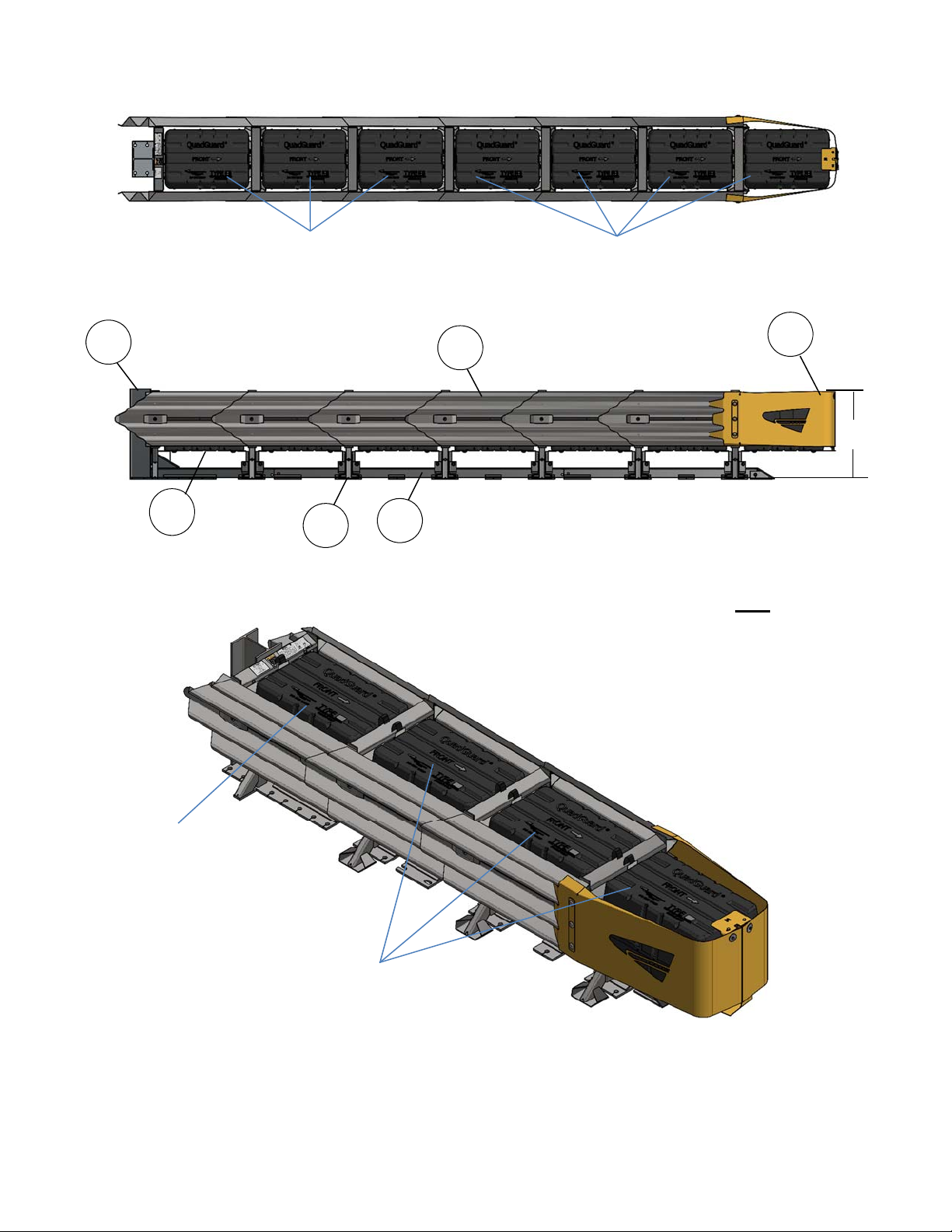
Figure 12 Elevation View
6 Bay TL-3
6
5
4
1 2 3
TYPE I
Figure 11 Plan View
TYPE II
FRONT
BACK
KEY
1) Backup
2) Quad-Beam Fender Panel
3) Nose Cover
4) Cartridge
5) Diaphragm
6) Monorail
Figure 13
3 Bay TL-2
TYPE II
TYPE I
32 1/8
ingalcivil.com.au
19 Revision E April 2021
Other manuals for QuadGuard Elite M10
2
Table of contents
Other Trinity Highway Industrial Equipment manuals


