Trinity Highway MPS 350X User manual


MPS
®
is
a
www.trini
t
The MP
S
Program
Federal
H
reimbur
s
This ma
times. F
o
The inst
informati
system i
n
changes
current i
n
a
registered t
r
t
yhighway.co
m
Truc
k
S
350
®
X s
y
(“NCHRP”)
H
ighway Ad
ement unde
Imp
o
asse
m
for st
a
the s
p
from
engin
e
use
o
High
w
nual must
b
o
r addition
a
ructions co
n
on, illustrati
n
formation
a
at any tim
e
n
structions.
r
ademark of
T
m
M
k
Mo
u
y
stem has
b
Report 350
ministration
r
the Federa
P
o
rtant:
T
h
m
bly, maint
e
a
ndard ass
e
p
ecified sy
s
standard a
e
e
r
. This sy
s
o
n the natio
n
w
ay repres
e
b
e availabl
e
a
l copies,
c
n
tained in t
ons, and s
p
a
vailable to
T
e
. Please c
o
T
rinity Indust
r
M
P
S
u
nte
d
b
een tested
specificati
o
(“FHWA”)
l-aid Highw
a
P
rodu
c
Asse
m
2525 N.
Dall
h
ese instru
c
e
nance, and
e
mblies spe
c
s
tem assem
ssembly p
a
s
tem has b
e
n
al highwa
y
e
ntatives are
e
to the wo
r
c
ontact Trin
his manual
p
ecification
s
T
rinity High
w
o
ntact Trinit
y
r
ies, Inc.
1
S
35
Atte
n
pursuant
t
o
ns. Based
o
determined
a
y Program.
c
t Des
c
m
bly
M
Stemmons
F
as, Texas 7
5
c
tions are
t
repair of M
c
ified by the
bly, mainte
n
a
rameters,
c
e
en deemed
y
system un
available f
o
r
ke
r
overse
e
ity Highwa
y
supersede
s
in this Ma
w
ay at the ti
m
y
Highway t
o
© 201
7
0
®
X
n
uat
o
t
o National
o
n a review
that the M
P
c
riptio
n
M
anual
F
reewa
y
5
207
t
o be use
d
M
PS 350
®
X
appropriat
e
n
ance, or r
e
c
ontact the
eligible for
n
der criteria
o
r consultati
o
e
ing and/o
r
y
at (888) 3
2
all previou
a
nual are b
a
me of printi
n
o
confirm t
h
7
Trinity High
w
Revision
X
o
r (“T
Cooperativ
e
of these c
r
P
S 350
®
X
s
n
d
only in
c
systems. T
h
e
highway a
e
pair would
appropriat
e
reimburse
m
utilized by
o
n if require
d
r
assembli
n
2
3-6374.
s informati
o
a
sed on th
e
n
g. We rese
h
at you are
r
Part No. 6
2
w
ay Product
s
C Decembe
r
MA”)
e
Highway
R
r
ash test re
s
s
ystem is el
c
onjunction
h
ese instru
c
uthority. In
t
require a
e
highway
m
ent by the
F
that agenc
y
d
.
n
g the prod
u
o
n and ma
n
e
latest MP
S
rve the righ
t
r
eferring to
2
0298
s
, LLC
r
2017
R
esearch
s
ults, the
igible for
with the
c
tions are
t
he event
deviation
authority
F
HW
A
for
y
. Trinity
u
ct at all
n
uals. All
S
350
®
X
t
to make
the most

www.trinityhighway.com 2 Revision C December 2017
Table of Contents
Customer Service Contacts..........................................................................................................3
Important Introductory Notes ........................................................................................................3
Safety Rules for Assembly............................................................................................................4
Safety Symbols.............................................................................................................................5
Limitations and Warnings..............................................................................................................6
Safety Instructions ........................................................................................................................7
Controlling Skid Distance (Roll Ahead).......................................................................................10
Assembly ....................................................................................................................................11
Inspect Shipment ..................................................................................................................11
Recommended Tools............................................................................................................11
Unpacking and Attaching the MPS 350®X ...........................................................................12
Operation Guidelines..................................................................................................................17
Raising and Lowering the System.........................................................................................17
Maintenance ...............................................................................................................................19
Recommended Routine Maintenance...................................................................................19
Winch System Operation............................................................................................................20
Lowering the MPS 350®X.....................................................................................................21
Raising the MPS 350®X.......................................................................................................22
Chain Retainer......................................................................................................................23
Removing the MPS 350®X From the Truck..........................................................................23
When the MPS 350®X is Impacted ............................................................................................24
Rapid Field Replacement of Shear Bolts..............................................................................24
Low-Speed Impact................................................................................................................25
Medium-Speed Impact..........................................................................................................25
High-Speed Impact ...............................................................................................................25
Troubleshooting Table ..........................................................................................................26
FRAME ASSEMBLY, MPS 350®X .......................................................................................27
HOIST ASSEMBLY, MPS 350®X, 12V ................................................................................29
MISC HARDWARE, MPS 350®X .........................................................................................31
LIGHT ASSEMBLY, MPS 350®X .........................................................................................32
STRIPING ASSEMBLY, MPS 350®X...................................................................................35
UNDERRIDE ASSEMBLY, RECEIVER TMA .......................................................................37
ATTACHMENT ASSEMBLY, MPS 350®X ...........................................................................38
CAB CONTROL ASSEMBLY, MPS 12V...............................................................................39

www.trin
Cust
o
Trinity H
i
350
®
X
s
welcom
e
Trinity
H
Teleph
o
E-mail:
Websit
e
Region
a
Center
v
Dallas,
Elizabe
t
Girard,
Orange
Impo
r
Proper
a
evaluate
d
in their
e
to be us
e
assembl
i
or have
planned
Departm
authority
this Man
ityhighway.
c
o
mer Se
i
ghway is c
o
s
ystem, its
e
. Additional
H
ighway
o
ne:
e
:
a
l Telepho
v
ille, Utah
Texas
t
htown, Ken
Ohio
burg, South
r
tant Int
r
a
ssembly o
f
d
and acce
p
e
ntirety and
u
e
d only in c
i
es only as
s
questions
a
and specifi
e
ent. This p
r
. If there ar
e
u
al, the dev
i
Imp
o
teste
d
c
om
rvice C
o
o
mmitted to
t
a
ssembly p
information
ne Conta
c
tucky
Carolina
r
oducto
f
the MPS
3
p
ted by the
u
nderstood
onjunction
w
s
pecified by
a
bout the M
P
e
d this ass
e
r
oduct must
e
deviations
i
ce may not
o
rtant:
DO
d
and/or ap
p
3
o
ntacts
t
he highest
rocedures,
s
can be obt
a
c
ts:
ry Note
s
3
50
®
X sys
FHWA per
N
before ass
e
w
ith the ass
e
the applica
b
P
S 350
®
X
e
mbly and,
i
be deploy
e
, alteration
s
perform as
NOT use a
p
roved fo
r
th
i
3
level of cus
t
s
upporting
d
a
ined from t
h
(888) 323
-
+1 (214)
5
product.in
f
www.trinit
y
(800) 772
-
(800) 527
-
(800) 282
-
(800) 321
-
(800) 835
-
s
tem is criti
c
N
CHRP Re
p
e
mbling the
M
e
mbly of th
e
b
le highway
system, ple
i
f needed,
c
e
d in the lo
c
s
, o
r
depart
u
i
t was teste
d
ny compon
e
i
s system d
u
t
omer servi
c
d
ocumentat
i
h
e contact i
n
-
6374 (USA
)
5
89-8140 (In
f
y
highway.c
o
-
7976
-
6050
-
7668
-
2755
-
9307
c
al to achi
e
p
ort 350. T
h
M
PS 350
®
X
e
MPS 350
®
authority. If
e
ase contac
t
c
ontact Trin
i
c
ation speci
f
u
res from th
e
d
.
e
nt part tha
t
u
ring the as
s
Revision
C
c
e. Feedbac
i
on, and pe
n
formation b
)
ternational)
o
m
e
ve perform
h
ese instruc
t
X
system. T
h
®
X system
a
you need a
d
t
the highw
a
i
ty Highway
’
f
ied by the
e
assembly
t
has not b
e
s
embly or r
e
C
Decembe
r
k regarding
rformance i
elow:
ance that
h
t
ions shoul
d
h
ese instru
c
a
nd are for
d
ditional inf
o
a
y authority
’s Custome
r
appropriate
protocol sp
e
e
en specific
a
e
pair of this
s
2017
the MPS
s always
h
as been
d
be read
c
tions are
standard
o
rmation,
that has
r
Se
r
vice
highway
ecified in
a
lly crash
s
ystem.

www.trin
This pr
o
provided
should b
possess
qualified
for an in
d
selected
Safet
y
* Import
a
This ma
n
experien
of this
m
product.i
informati
A
lways
equipme
protectio
Safety
m
used to
control p
ityhighway.
c
o
duct has b
to that use
r
e permitted
the unique
to both rea
d
d
ividual exp
e
by the high
w
Imp
o
and s
350
®
X
work
e
FHW
A
invol
v
War
n
and I
m
Failu
r
collisi
o
y
Rules
a
nt Safety I
n
ual must b
e
ced in the
a
m
anual are
t
on in this m
a
use appro
p
nt or MPS
3
n shall be u
s
m
easures in
c
provide saf
e
lan that has
c
om
een specifi
e
r
who has u
n
to assist in
knowledge
d
and accur
a
e
rienced an
d
w
ay authori
t
o
rtant:
Rea
d
uggested s
a
X
system.
F
e
rs and/or b
y
A
. Please k
e
v
ed in the as
n
ing:
Ens
u
m
portant st
a
r
e to follow
t
o
n.
for Ass
e
nstruction
s
e
kept in a l
a
ssembly, m
available
f
t
. Please c
o
a
nual or ab
o
p
riate safet
y
3
50
®
X com
s
ed.
c
orporating
e
ty for pers
o
been estab
4
e
d for use
n
ique knowl
e
the assem
b
described
a
a
tely interpr
e
d
skilled in t
t
y.
d
safety ins
t
a
fe practice
s
F
ailure to fol
y
standers. I
t
e
ep up-to-d
a
sembly of t
h
u
re that all
o
a
tements wi
t
his warning
e
mbly
s
*
ocation wh
e
aintenance,
f
rom Trinity
o
ntact Trini
t
o
ut the MPS
y
precautio
n
ponents. W
traffic contr
o
o
nnel while
lished by th
e
4
by the ap
p
e
dge of ho
w
b
ly, mainten
a
bove. Thes
e
e
t them as
w
he assembl
y
t
ructions th
o
s
before as
s
low this wa
r
t
further co
m
a
te instructi
h
e product.
o
f the MPS
thin the M
P
could resul
e
re it is rea
d
or repair o
f
Highway
b
t
y Highway
350
®
X sys
t
n
s when o
p
ork gloves,
o
l devices
s
TMA is in
e
highway a
p
ropriate hi
g
w
this syste
m
ance, or re
p
e instructio
n
w
ritten. The
s
y
of highwa
y
o
roughly an
d
s
embling, m
r
ning can r
e
m
promises t
h
ons for lat
e
350
®
X sy
s
P
S 350
®
X
m
t in serious
d
ily availabl
e
f
the MPS 3
b
y calling (
if you hav
e
t
em.
p
erating po
w
safety gog
g
s
pecified b
y
use. TMA
p
uthority for
T
Revision
C
g
hway aut
h
m
is to be a
s
p
air of this
s
n
s are inten
d
s
e instructi
o
y
products t
h
d
follow the
aintaining,
o
e
sult in seri
o
h
e eligibility
e
r use and
r
s
tem Dange
m
anual are
injury or d
e
e
to person
s
3
50
®
X syst
e
888) 323-6
3
e
any ques
t
wer equip
m
g
les, safety-
t
y
the highw
a
p
ersonnel
m
T
MA use.
C
Decembe
r
h
ority and
h
s
sembled. N
s
ystem that
d
ed for an i
o
ns are inte
n
h
at are spe
c
assembly
d
o
r
r
epairing
o
us injury or
of this syst
e
r
eference b
y
r, Warning,
completely
e
ath in the e
s
who are s
k
e
m. Addition
3
74 or by
t
ions conce
r
m
ent, movi
n
t
oe shoes,
a
a
y authority
m
ust follow t
2017
h
as been
o person
does not
ndividual
n
ded only
c
ified and
d
irections
the MPS
death to
e
m by the
y
anyone
Caution,
followed.
vent of a
k
illed and
al copies
email at
r
ning the
n
g heavy
a
nd back
must be
he traffic

www.trin
Safet
y
This se
c
manual
f
Symbo
l
ityhighway.
c
y
Symb
o
c
tion descri
b
f
or complete
l
Mean
Safe
t
read
a
in ser
War
n
serio
u
been
War
n
have
Dang
e
comp
unde
r
War
n
speci
f
deplo
y
in th
e
autho
War
n
MPS
3
utiliz
e
are o
t
have
unsp
e
could
UNA
C
War
n
War
n
feder
a
War
n
Traffi
c
c
om
o
ls
b
es the saf
e
safety, ass
e
ing
t
y Alert S
y
a
nd follow t
h
ious injury
o
n
ing:
Failu
u
s injury or
accepted b
y
n
ing:
Do n
o
read this
m
e
r, Warnin
g
l
etely follo
w
r
stand these
n
ing:
Safe
t
f
ied by the
h
y
ment site.
e
event of
rity must al
w
n
ing:
Use
3
50
®
X for
a
e
or other
w
t
her Trinity
they been
d
e
cified parts
result in s
C
CEPTED s
y
n
ing:
Do N
O
n
ing:
Ensu
r
a
l, state, sp
e
n
ing:
Ensu
r
c
Control D
e
5
e
ty symbol
s
e
mbly, oper
a
y
mbol:
Indi
c
h
e Danger,
o
r death to
w
re to compl
death in th
e
y
the FHWA
.
o
t assembl
e
m
anual thor
o
g
, Caution,
w
ed. Please
inst
r
uction
s
t
y measur
e
h
ighway aut
h
Failure to f
o
a collision.
w
ays be obs
only Trinit
y
a
ssembling,
w
ise comin
g
Highway
s
d
eemed eli
g
or access
o
erious injur
y
y
stem.
O
T modify t
h
r
e that the
e
cifying age
n
r
e that you
r
e
vices (“MU
T
5
s
that appe
a
a
ting, maint
e
c
ates Import
Warning, C
a
w
orkers and/
o
y with thes
e
e
event of
a
.
e
, maintain,
o
ughly and
and Imp
o
call Trinity
s
.
e
s, incorpo
r
h
ority, must
o
llow this w
a
The traffic
erved in util
i
y
Highway
maintaining
g
le parts fr
o
s
ystems. S
u
g
ible for us
e
o
ries is stric
t
y
or death
h
e MPS 350
®
MPS 350
®
n
cy, and loc
a
r
assembly
T
CD”) and l
o
a
r in this
M
e
nance, rep
t
ant, Cautio
n
a
ution, or I
m
o
r bystande
e
warnings
a
vehicle im
p
or repair th
completel
y
o
rtant state
m
Highway a
r
ating app
r
be used to
p
a
rning could
control pl
a
i
zing this pr
o
parts that
, or repairin
g
o
m other s
y
u
ch configur
a
e
.
A
ssembl
y
t
ly prohibite
in the eve
®
X system i
X system
al specifica
t
meets all
a
o
cal standar
d
Revision
C
M
PS 350
®
X
air, and ser
v
n
, Warning,
o
m
portant st
a
rs.
could resul
t
p
act with a
e MPS 350
®
y
understan
d
m
ents with
t (888) 32
3
r
opriate tra
f
p
rotect all p
e
result in s
e
a
n establis
h
o
duct.
are speci
g
the MPS
3
y
stems ev
e
a
tions have
y
, maintena
n
d. Failure t
o
nt of a ve
h
n any way.
and deline
a
t
ions.
a
ppropriate
d
s.
C
Decembe
r
X
manual.
R
v
ice informa
o
r Danger.
F
a
tements co
u
t
in increas
e
system tha
t
®
X system
d
it. Ensur
e
in the ma
n
3
-6374 if yo
f
fic control
e
rsonnel w
h
e
rious injury
h
ed by the
fied herein
3
50
®
syste
m
e
n if those
not been t
e
n
ce, or rep
a
o
follow thi
s
h
icle impac
t
a
tion used
Manual on
2017
R
ead the
tion.
F
ailure to
u
ld result
e
d risk of
t
has not
until you
e
that all
n
ual are
u do not
devices
h
ile at the
or death
highway
for the
m
. Do not
systems
e
sted, nor
a
irs using
s
warning
t
with an
meet all
Uniform

www.trinityhighway.com 6 Revision C December 2017
Limitations and Warnings
Trinity Highway, in compliance with the NCHRP Report 350 “Recommended Procedures for the
Safety Performance of Highway Safety Features”, contracts with FHWA approved testing facilities
to perform crash tests, evaluation of tests, and submittal of results to the FHWA for review.
The MPS 350®X system was tested to meet the impact criteria, requirements, and guidelines of
NCHRP Report 350. These tests, specifically set forth by FHWA, evaluate product performance by
utilizing established impacts outlined by NCHRP Report 350 involving a range of vehicles on the
roadways, from lightweight cars (approx. 820kg [1800 lb.]) to full size pickup trucks (approx. 2000
kg [4400 lb.]) as specified by the appropriate highway agency. A product can be certified for
multiple Test Levels. The MPS 350®X system is certified to the Test Level(s) as shown below:
Test Level 3: 100 km/h [62 mph]
These FHWA directed tests are not intended to represent the performance of systems when
impacted by every vehicle type or every impact condition existing on the roadway. This
system is tested only to the test matrix criteria of NCHRP Report 350 as approved by FHWA.
Additionally, the MPS 350®X system was tested to meet the impact criteria, requirements, and
guidelines of TD 49. These tests, specifically set forth by The Highways Agency, evaluate product
performance by simulating those impacts outlined by TD 49 involving a typical range of vehicles on
our roadways, from lightweight cars (approx. 900 kg [2000 lbs.]) to heavier cars (approx. 1500 kg
[3300 lbs.]) as specified by The Highways Agency. A product can be certified for various speed
levels as shown below:
TL3.UK: 110 km/h [68 mph]
Highways Agency directed tests are not intended to represent the performance of systems
when impacted by every vehicle type or every impact condition existing on the roadway.
This system is tested only to the test matrix criteria of TD 49 as approved by the Highways
Agency.
Trinity Highway expressly disclaims any warranty or liability for injury or damage to persons or
property resulting from any impact, collision or harmful contact with products, other vehicles, or
nearby hazards or objects by any vehicle, object or person, whether or not the products were
assembled in consultation with Trinity Highway or by third parties.
The MPS 350®X system is intended to be assembled, delineated, and maintained within specific
state and federal guidelines. It is important for the highway authority specifying the use of a highway
product to select the most appropriate product configuration for its site specifications. The customer
should be careful to properly select, assemble, and maintain the product. Careful evaluation of the
site lay out, vehicle population type; speed, traffic direction, and visibility are some of the elements
that require evaluation in the selection of a highway product.
After an impact occurs, the debris from the impact should be removed from the area immediately
and the product should be evaluated and restored to its original specified condition or replaced as
soon as possible. All components and assemblies should be inspected and any parts that are
damaged should be replaced with original Trinity Highway replacement parts. Contact the Customer
Service Department prior to repair if you have any questions (see p. 3).

www.trin
Safet
y
For the
s
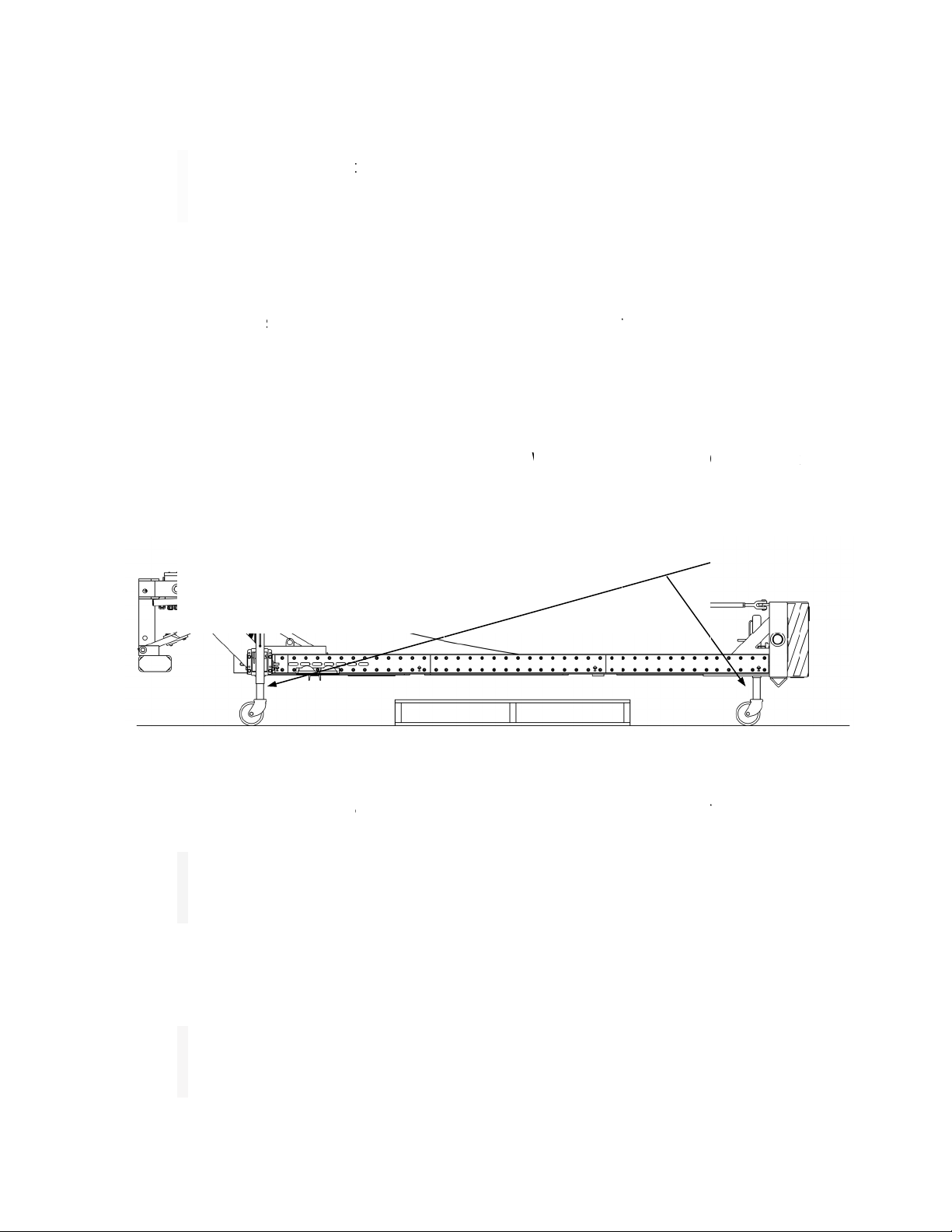
When til
t
1.
T
T
o
T
w
2. J
a
F
a
ityhighway.
c
y
Instru
c
s
afety of the
t
ing the TM
A
T
he TMA sh
a
T
MA shall b
e
n p. 11). Th
T
MA can onl
y
w
hen in the
D
a
cks shall
b
igure 2). R
o
t
tached to t
h
War
n
Jack
s
maint
e
Dan
g
oper
a
c
om
c
tions
operato
r
, th
A
, stay clear
a
ll be fasten
e
e
280 to 33
0
e TMA mu
s
y
absorb th
e
D
OWN (hori
z
b
e used to
s
o
tate or sw
i
h
e truck.
n
ing:
Do n
o
s
provided.
e
nance acti
v
g
er:
Ensur
e
tion.
7
e operator
s
of all movin
e
d to the tru
0
mm [11" t
o
s
t be left in t
e
energy of
a
z
ontal) posi
t
s
upport the
i
vel Jacks i
n
o
t use han
d
A
lways ke
e
v
ities.
e
that no o
n
7
s
hall stand
a
g parts.
ck. In the D
O
o
13"] from
t
he DOWN
(
a
n impactin
g
t
ion.
Figur
e
MPS 350
®
n
to the sto
r
Figur
e
s or feet to
e
p feet cle
a
n
e is near,
a
t the rea
r
o
f
OWN (horiz
t
he ground
a
(
horizontal)
p
g
vehicle, wi
e
1
X when it
i
r
age (horiz
o
e
2
lift or supp
o
a
r of frame
under or b
e
Revision
C
f
the truck o
n
z
ontal) positi
o
a
nd level (s
e
p
osition wh
e
i
thin NCHR
P
i
s detached
o
ntal) positi
o
o
rt the MPS
when in o
e
hind the
M
C
Decembe
r
n
the non-tr
a
o
n, the bott
o
e
e
A
ssembl
y
e
never pos
s
P
Report 35
0
from the t
r
o
n when th
e
350
®
X. Al
w
peration a
n
M
PS 350
®
X
2017
a
ffic side.
o
m of the
y
section
s
ible. The
0
criteria,
r
uck (see
e
TM
A
is
w
ays use
n
d during
when in

www.trin
3.
B
o
t
h
4.
W
s
e
F
5.
C
i
s
d
i
n
Safety
C
ityhighway.
c
Caut
i
not d
r
not si
t
B
efore raisi
n
peration.
A
l
l
h
e system.
N
W
hen traveli
e
cure the fr
a
igures 3 &
4
Figu
r
C
onfirm all p
e
s
stopped in
irectly behi
n
n
the raised
Caut
i
the U
P
C
hains
c
om
i
on:
The
M
r
ag the TM
A
t
, stand, or l
e
g or loweri
l
operators
s
N
ever stand
ng long dis
a
me with th
e
4
).
e 3
e
rsons are
s
full UP (ve
r
n
d the eleva
t
position or
w
i
on:
Whe
n
P
(vertical)
t
8
M
PS 350
®
X
A
or place a
e
an on any
p
ng the TM
A
s
hall fully u
n
under the T
tances or
s
e
Safety Ch
s
tanding cle
a
r
tical) positi
o
t
ed system.
w
hile it is be
i
n
traveling t
o
t
raveling po
s
Linchpi
n
Chain
(
S
8
X
system is i
nything on
t
p
art of the
T
A
, the oper
a
n
derstand t
h
MA when a
t
s
toring the
T
ains using
t
a
r before ra
i
o
n and retai
Never allo
w
i
ng lowered.
o
and from
a
s
ition.
n
Securing S
a
(
Chain Cove
r
hown For Cl
a
i
ntended to
t
op of the s
y
T
MA.
a
tor shall
b
h
e contents
o
t
tempting to
T
MA in the
t
he Linchpin
i
sing or low
e
ning chain i
w
anyone to
.
a
work zon
e
a
fety
r
Not
a
rity)
Revision
C
only suppo
r
y
stem as d
a
b
e fully trai
n
of this Man
u
lower it.
UP (vertic
a
n
s provided
w
Figure 4
e
ring the T
M
s in use be
f
stand und
e
e
, travel wit
h
C
Decembe
r
r
t its own w
e
a
mage will r
e
n
ed as to i
t
u
al prior to
o
a
l) position,
w
ith the sys
M
A. Verify th
e
f
ore allowin
g
e
r the TMA
w
h
the MPS
3
2017
e
ight. Do
e
sult. Do
t
s proper
o
perating
properly
s
tem (see
e system
g
anyone
w
hen it is
3
50
®
X in

www.trin
6.
B
p
N
a
7.
T
e
8. It
6
a
9.
T
D
10.
T
p
11.
T
t
r
t
r
12.
T
I
m
t
o
13.
T
i
m
ityhighway.
c
B
allast and
o
revent shifti
n
N
ote:
The
f
n impact.
T
he agency
o
quipment (
e
is required
804 kg [15
,
ppropriate
s
T
he driver s
h
D
OWN (hori
z
T
he driver s
h
osition. The
Caut
i
while
Fram
e
T
his system
i
r
affic lane w
r
uck and/or i
T
he Winch
A
m
proper us
a
o
the syste
m
T
he system
m
pact. Do n
o
Caut
i
(55 k
m
slow
e
occur
s
c
om
o
ther heav
y
n
g during a
n
f
orce on the
o
r authority
r
e
.g., seat bel
that the M
,
000 lbs.]
t
s
tate and fe
d
h
all be caut
i
z
ontal) posit
i
h
all be cau
t
TMA exten
d
i
on:
Do n
o
the MPS 3
5
e
Assembly
i
s an impac
t
henever po
s
mpacting v
e
A
ssembly
s
a
ge will cau
s
m
.
must be in
o
t leave the
i
on:
While
m
/hr) with
M
e
r than 35
m
s
or various
9
y
objects M
n
impact (se
e
tie-down s
t
r
esponsible
ts, head re
s
PS 350
®
X
t
o achieve
d
eral guideli
n
i
ous while
o
on so that i
n
t
ious while
d
s beyond t
h
o
t leave th
e
5
0
®
X is bei
n
could be da
t
attenuator
s
sible. If th
e
e
hicle that c
o
s
ystem was
s
e the lift m
e
the DOW
N
system rais
e
traveling in
M
PS 350
®
X
m
ph (55 km/
h
road condit
i
9
UST BE A
D
e
Figure 5).
t
raps could
b
Figure 5
for the truc
k
s
ts, etc.).
system be
intended i
m
n
es (see p.
1
o
perating th
e
n
jury and/or
Figure 6
making tur
n
h
e end of th
e
e
Winch St
r
n
g used as t
maged.
and is ofte
n
e
system is
i
o
uld cause i
n
solely de
s
e
chanism to
N
(horizont
a
e
d, even sli
g
a moving
w
X
in a DO
W
h
r) will be r
e
i
ons dictate.
D
EQUATE
L
be 20 time
s
k
shall inspe
c
mounted t
o
m
pact perf
o
1
0).
e
truck with
damage wil
n
s with the
e
truck and
w
r
ap tight in
he Winch a
n
n
used in hi
g
impacted, t
h
n
jury or dea
s
igned to li
f
o
malfunctio
n
a
l) position
t
g
htly, during
w
ork zone,
N
W
N (horizo
n
e
quired wh
e
Revision
C
L
Y ANCHO
R
s
the weight
c
t it for ade
q
o
trucks wei
o
rmance o
f
the TMA i
n
l not result
(
TMA in th
e
w
ill swing w
the DOWN
n
d/or the at
t
g
h traffic ris
k
h
ere may b
e
th.
f
t and low
e
n
and caus
e
t
o perform
g
worksite o
p
N
EVER driv
e
n
tal) operati
e
n bouncin
g
C
Decembe
r
R
ED to the
of the ball
a
q
uate opera
t
ghing a mi
n
f
the syste
m
n
the UP (v
e
(
see Figure
6
e
DOWN (h
o
w
ide while tu
r
(horizontal
)
t
achment p
o
k
areas. Sta
y
e
fragments
e
r the TMA
e
permanen
t
as tested
d
p
erations.
e
faster tha
n
ng position
.
g
of the MP
S
2017
truck to
a
st during
t
or safety
n
imum o
f
m
under
e
rtical) or
6
).
o
rizontal)
r
ning.
)
position
o
int to the
y
clear of
from the
system.
t
damage
d
uring an
n
35 mph
.
Speeds
S
350
®
X

www.trinityhighway.com 10 Revision C December 2017
Controlling Skid Distance (Roll Ahead)
The use of a TMA on the back of a truck will not:
Affect the skid (roll ahead) distance of an impacted truck. KEEP WORK CREWS CLEAR!
Controlling skid distance (roll ahead):
Skid distance is significantly increased and is less predictable for lightweight shadow
vehicles.
Skid distance is reduced and is more consistent when heavier shadow vehicles are used.
Required minimum truck weight: 6,804 kg. [15,000 lbs.] or greater.
Roll-Ahead Distance for Shadow Vehicles
Weight of Shadow
Vehicle (Moving)
Prevailing
Speed km/h
[mph]
Weight of Impacting Vehicle to be Contained*
2,040 kg
[4,500 lbs] 4,536 kg
[10,000 lbs] 6,804 kg
[15,000 lbs] 10,886 kg
[24,000 lbs]
6,804 kg [15,000 lb] 96-105 [60-65] 23 m [75 ft] 46 m [150 ft] 53 m [175 ft] 69 m [225 ft]
80-88 [50-55] 23 m [75 ft] 38 m [125 ft] 46 m [150 ft] 53 m [175 ft]
72 [45] 15 m [50 ft] 30 m [100 ft] 30 m [100 ft] 30 m [100 ft]
10,886 kg [24,000 lb] 96-105 [60-65] 23 m [75 ft] 30 m [100 ft] 46 m [150 ft] 53 m [175 ft]
80-88 [50-55] 15 m [50 ft] 23 m [75 ft] 30 m [100 ft] 46 m [150 ft]
72 [45] 15 m [50 ft] 23 m [75 ft] 23 m [75 ft] 30 m [100 ft]
Note: Distances are applicable for shadow vehicle speeds up to 25 km/h [15 mph].
Roll-Ahead Distance for Barrier Vehicles
Weight of Barrier
Vehicle (Stationary)
Prevailing
Speed km/h
[mph]
Weight of Impacting Vehicle to be Contained*
2,040 kg
[4,500 lbs] 4,536 kg
[10,000 lbs] 6,804 kg
[15,000 lbs] 10,886 kg
[24,000 lbs]
6,804 kg [15,000 lb] 96-105 [60-65] 8 m [25 ft] 23 m [75 ft] 30 m [100 ft] 46 m [150 ft]
80-88 [50-55] 8 m [25 ft] 15 m [50 ft] 23 m [75 ft] 30 m [100 ft]
72 [45] 8 m [25 ft] 8 m [25 ft] 15 m [50 ft] 23 m [75 ft]
10,886 kg [24,000 lb] 96-105 [60-65] 8 m [25 ft] 15 m [50 ft] 23 m [75 ft] 30 m [100 ft]
80-88 [50-55] 8 m [25 ft] 8 m [25 ft] 15 m [50 ft] 23 m [75 ft]
72 [45] 8 m [25 ft] 8 m [25 ft] 8 m [25 ft] 15 m [50 ft]
*Weights of Typical Vehicles:
Midsize automobile - 1,020 kg [2,250 lb]
Full-size automobile - 1,500 kg [3,500 lb]
Loaded 3/4-ton pickup truck - 2,750 kg [6,000 lb]
Loaded 1-ton cargo truck - 4,500 kg [10,000 lb]
Loaded 4-yard dump truck - 11,000 kg [24,000 lb]
Source: "Use of Truck Mounted Attenuators in Work Zones" by Jack B. Humphreys, P.E. and T.
Darcy Sullivan, P.E., University of Tennessee.

www.trin
Asse
m
Read an
d
If syste
m
rear lea
f
(AWS)
q
battery
b
The tru
c
question
s
that spe
agency.
Only us
e
specifyin
Inspe
c
Carefull
y
parts ag
a
Reco
m
W
C
H
T
1
/
1
/
O
1
M
F
C
W
B
Note:
T
extensi
v
specifie
d
what to
o
highwa
y
system
a
ityhighway.
c
m
bly
d
understan
Imp
o
[15,0
0
appr
o
m
must be a
f
spring ha
n
q
ualified wel
efore any w
k frame m
u
s
regarding
cified this
s
e
reflective
s
g the use o
f
c
t Shipm
e
y
uncrate all
a
inst the shi
p
m
mended
W
elding equi
C
utting torch
H
amme
r
T
ape measu
r
/
2” drive so
c
/
2” drive so
c
O
pen end wr
e
2” crescent
M
arking impl
e
loor jack or
C
enter punc
h
W
ork gloves
B
ubble level
T
he above l
i
v
e list. Dep
d
by the a
p
o
ls are nee
d
y
authority
a
t the auth
o
c
om
d all instruc
t
o
rtant:
Th
e
0
0 lbs.] to
o
priate state
ttached to t
n
gers to en
s
ders to ens
elding on th
u
st be suita
b
the suitabil
s
ystem for
s
triping patt
e
f
this TMA.
e
nt
componen
t
p
ping list su
Tools
pment GM
A
r
e
c
ket wrench
c
kets (9/16”,
e
nches (9/1
w
renches (
2
e
ment (pen
c
Forklift
h
and other p
e
i
st of tools
ending on
p
propriate
h
d
ed to perf
and the a
u
o
rity’s spe
c
1
t
ions before
e
truck wei
g
achieve i
n
and federal
he truck by
s
ure struct
u
ure durable
e truck or T
M
b
le and ac
c
ity, please
guidance.
T
e
rns that ha
v
t
s. Before a
s
pplied with
t
A
W or SMA
W
w/ 6” exten
s
1-1/8”, 1-1/
6
”, 1-1/8”,1-
2
)
c
il, soap sto
n
e
rsonal prot
e
is a gener
a
specific si
h
ighway au
t
o
rm the jo
b
u
thority’s s
e
c
ified asse
m
1
beginning
a
g
ht, excludi
n
tended i
m
guidelines.
welding pa
r
u
ral integrity
attachmen
t
M
A.
c
essible for
c
ontact the
T
rinity High
w
v
e been sp
e
s
sembling t
h
t
he system.
V
W
s
ion
2”)
1/2”)
n
e)
e
ction equi
p
a
l recomme
n
te conditi
o
t
hority the
b
are entir
e
e
lected co
n
m
bly site.
a
ssembly.
ng TMA,
m
m
pact perfo
r
r
ts to the fr
a
y
of frame.
t
of the TM
A
mounting
a
appropriat
e
w
ay is ava
i
e
cifically ap
p
h
e MPS 35
0
V
erify that
a
p
ment as re
q
n
dation an
d
o
ns and th
e
required t
o
e
ly within t
h
n
tractor pe
Revision
C
m
ust be a
m
rmance of
a
me, do no
t
Use
A
meri
c
A system.
D
a
TMA syst
e
e
highway
a
i
lable for c
o
proved by t
h
0
®
X system
a
ll parts wer
e
q
uired
d
should n
o
e
complexi
t
o
ols may v
a
h
e discreti
o
rforming t
h
C
Decembe
r
m
inimum o
f
the syste
m
t
weld forw
a
c
an Weldin
g
D
isconnect
e
m. If there
a
uthority or
e
o
nsultation
w
h
e highway
, check the
e
received.
o
t be consi
d
t
y of the a
a
ry. Decisi
o
o
n of the s
p
h
e assemb
l
2017
6804 kg
m
under
a
rd of the
g
Society
the truck
are any
e
nd user
w
ith that
authority
received
d
ered an
ssembly
o
ns as to
p
ecifying
l
y of the
www.trin
Unpa
c
1.
R
2.
R
m
3.
R
c
a
4.
O
H
m
5.
R
x
t
h
R
6.
C
7. I
n
C
8.
A
M
b
ityhighway.
c
c
king and
Caut
i
is mo
10’-6
”
R
ead safety i
R
emove the
m
aterials.
R
emove pla
s
a
rdboard b
o
O
pen the
M
H
ardware
As
m
issing (see
R
emove the
1” Hex Bol
t
h
e Misc. Ha
r
R
aise the M
P
C
onfirm the t
n
form the tr
u
C
hock the w
h
Caut
i
attac
h
the ig
NOT
S
A
dd load to t
h
M
PS 350
®
X
e different f
o
War
n
other
oper
a
c
om
Attachi
n
i
on:
Prior
t
re than 10’
-
(3.2 m), co
n
nstructions
t
shipping
b
s
tic Stripin
g
o
x with the
M
M
iscellaneo
u
s
sembly (se
e
p. 3).
s
hipping st
a
t
s (PN 113
5
r
dware Ass
e
P
S 350
®
X o
f
r
uck is on fl
a
u
ck driver th
a
h
eels to pre
v
i
on:
A
lwa
h
ed, repaire
d
nition of th
e
S
TART EN
G
h
e truck; if
a
is attached
o
r local reg
u
n
ing:
Do
n
loose acc
e
tion.
1
n
g the M
P
t
o mounting
-
6” (3.2 m)
n
tact Trinity
t
horoughly
b
b
ands and
g
Assembl
y
M
iscellaneou
s Hardwar
e
e
drawing
6
a
nds and att
5
98G) and f
o
e
mbly.
f
f the shippi
n
a
t level grou
a
t the MPS
v
ent truck m
ys i
nform t
d
, operated,
e
truck and
G
INE.
a
pplicable, t
h
. The mini
m
u
lations. Co
n
n
ot operate
t
e
ssories, w
h
2
P
S 350
®
X
the MPS 3
5
from the re
Highway a
b
b
efore oper
a
protective
m
y
compone
n
s Hardware
e
box and
6
20358 on
p
a
ch the thr
e
o
u
r
(4) 3/8”
W
n
g pallet usi
n
Figure 8
nd.
350
®
X is g
o
ovement. D
o
he truck dr
i
or adjuste
d
place signs
h
e truck mu
s
m
um loaded
n
sult your lo
c
t
he MPS 3
5
h
ich may b
e
X
5
0
®
X, verify
ar of the tr
u
b
out various
a
ting the M
P
m
aterial. P
r
n
ts (see d
r
.
inventory
p
. 31). Con
t
e
e (3) Jacks
W
hiz Nuts (
ng the stora
o
ing to be a
o
not start
t
i
ver when t
h
d
. Chock th
e
on the tru
c
s
t be loade
d
weight is 6,
c
al governin
5
0
®
X while
e
come tang
Revision
C
that the fu
e
u
ck. If the
d
extensions
P
S 350
®
X.
r
operly dis
p
r
awing 620
3
items from
t
act Trinity
H
(PN 00567
8
(
PN 003257
G
a
ge Jacks.
ssembled,
r
t
ruck engi
n
h
e MPS 3
5
e
wheels. R
e
c
k that it is
b
d
to the corr
e
804 kg (15,
g specificati
wearing lo
o
led in the
M
J
C
Decembe
r
e
l tank(s) on
d
istance is l
(see p. 3).
p
ose of all
3
44 on p.
the Misc
e
H
ighway if
p
8
B) with fou
G
) per Jac
k
r
epaired, or
a
n
e.
5
0
®
X is goi
e
move the
k
b
eing servi
c
e
ct weight b
000 lbs.). T
i
ons.
o
se fitting cl
M
PS 350
®
J
acks
2017
the truck
ess than
shipping
35) and
e
llaneous
p
arts are
r (4) 3/8”
k
found in
a
djusted.
ng to be
k
eys from
c
ed – DO
efore the
his could
othing or
X during
www.trin
9.
M
a
(
9
10.
S
ityhighway.
c
M
ove the M
P
ssembled h
e
9
15 mm) an
d
Imp
o
perfo
r
crash
Caut
i
A
sse
m
not o
b
the tr
u
S
elect the b
e
A. This
fram
e
atta
c
shou
of th
e
brac
e
Wel
d
rear-
reco
m
c
om
P
S 350
®
X i
n
e
ight at 915
d
maximum
o
rtant:
Pro
p
r
mance of t
h
.
i
on:
Leav
e
m
bly and di
r
b
structed du
u
ck and the
e
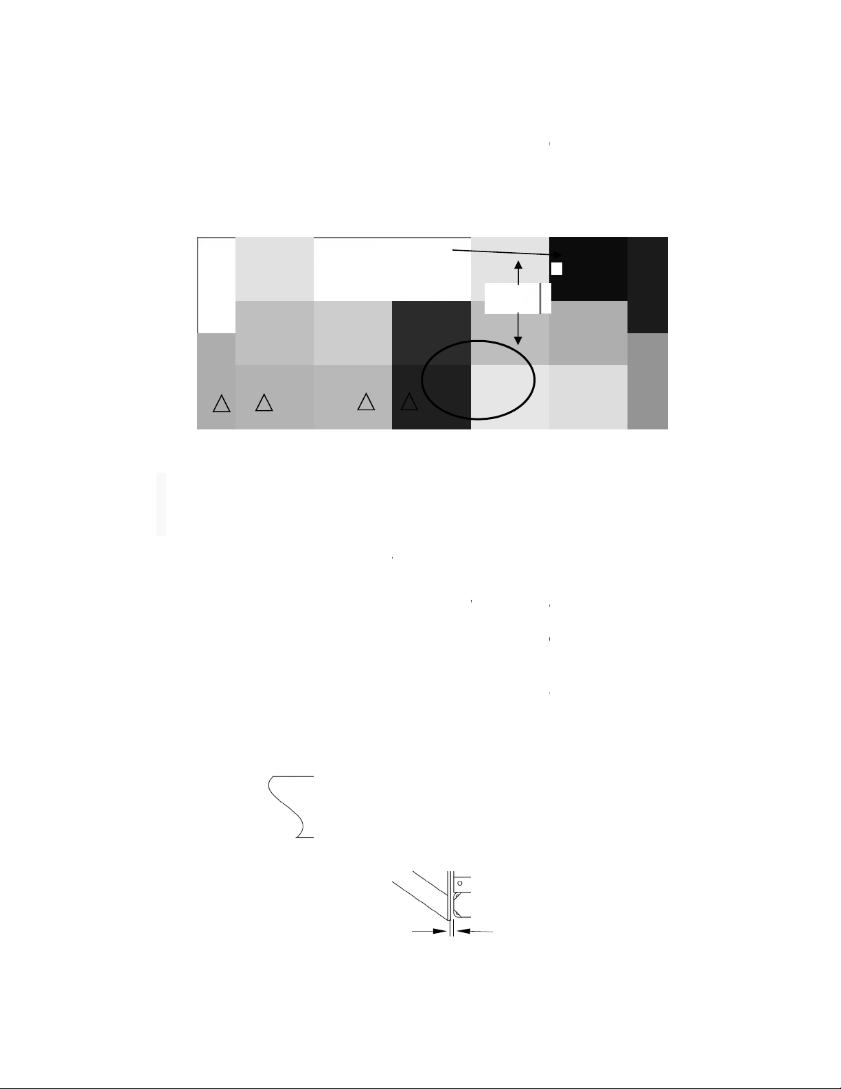
st mounting
option uses
e
rails as s
h
c
hment poin
ld allow 1/2
”
e
MPS 350
®
e
d to the t
r
u
d
the Chan
n
most leaf
s
m
mendatio
n
1
n
to position
a
mm [+ 12
m
height of 3
6
p
er mountin
g
h
e system
u
e
adequate
r
ectly in fro
n
ring an imp
a
MPS 350
®
X
option for
y
a minimum
h
own in Fig
u
ts for the
M
”
(13 mm)
o
®
X Bumper
u
ck frame u
n
els to the
t
s
pring han
g
n
s regarding
P
1
/
2” [13
m
3
a
t the back
o
m
m /- 0 mm
]
6
-1/2” (927
m
g
height mu
s
u
nder appro
Figure 9
(4” minim
u
n
t of the Sh
e
a
ct. Failure
t
X
.
y
our applica
t
1/2” (13 m
m
u
re 10 belo
w
M
PS 350
®
X
o
f clearance
and the M
o
sing the “C
”
t
ruck
f
rame
g
er, followin
attachment
Figure 10
ivot Bolt
m
m]
o
f the truck.
]
(36” [+ 1/2
m
m) to the c
e
st be maint
a
priate state
u
m) clear a
r
e
ar Bars to
t
o follow thi
s
t
ion.
m
) Plate wel
w
. Mount T
a
X
Bumper.
between th
e
o
unting Plat
e
”
Channels
as fa
r
forw
a
n
g the truc
k
methods.
36”
915 mm
Revision
C
Use the Ja
c
” /- 0”]), (mi
enter of the
a
ined to ach
and federa
r
ea directly
ensure tha
t
s
warning wi
l
ded across
abs welded
The length
e Lower Bu
e
. The Mou
n
provided w
i
ard as pos
s
k
manufact
u
C
Decembe
r
c
ks to set t
h
nimum hei
g
Pivot Bolt.
ieve intend
e
l guidelines
behind the
t
the Shear
ll result in d
a
the back of
to the plat
e
of the Mo
u
mper Cross
n
ting Plate
s
i
th the MP
S
s
ible, but b
e
u
rer’s warn
i
2017
h
e correct
g
ht of 36”
e
d impact
during a
Bumper
Bars are
a
mage to
the truck
e
provide
u
nt Tabs
Member
s
hould be
S
350
®
X.
e
hind the
i
ngs and
www.trin
11.
A
T
t
o
p
12.
C
g
w
f
r
C
13.
P
W
(
s
P
t
h
S
o
ityhighway.
c
B. This
rails.
for t
h
Low
e
to th
e
C. Soc
k
Con
t
parti
c
Imp
o
A
WS
A
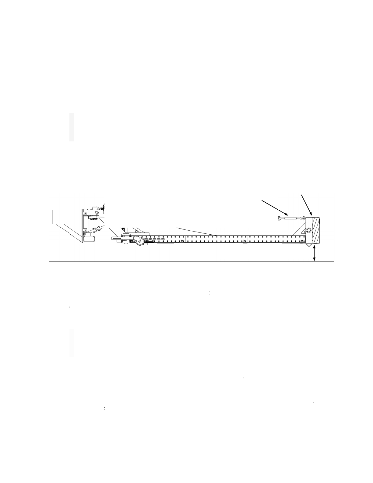
fter the M
P
T
urnbuckles.
o
330 mm) f
r
osition on t
h
C
onnect the
W
round cond
u
w
elding cabl
e
r
om the truc
C
ontrols. Tri
n
Caut
i
batte
r
truck
P
ush and h
o
W
inch Strap.
s
ee Figures
P
osition the
W
h
rough the
C
S
ecure by in
s
ut the ends
c
om
option invo
Welding o
n
h
e Lower B
u
e
r Bumper
C
e
truck fram
e
k
et Hitch Op
t
act Trinity
H
c
ular applic
a
o
rtant:
A
ll
w
D1.1. Disco
P
S 350
®
X i
The botto
m
r
om the gro
u
h
e TM
A
for l
a
W
inch by ro
u
ctors) fro
m
e
quick-dis
c
k and enab
l
n
ity Highwa
y
i
on:
For o
v
r
y should b
e
b
attery.
o
ld the DO
W
Un-spool t
h
12 and 1
3
W
inch Stra
p
C
ross Bar
T
s
erting the
C
of the cotte
r
1
lves weldin
g
n
the “C” Ch
a
u
mper Cros
C
ross Mem
b
e
rails.
t
ion (see p.
3
H
ighway to
a
tion (see p.
w
elding mu
s
nnect truck
s mounted
m
edge of th
e
u
nd (see Fi
g
a
ter use (se
e
uting two (2
)
m
the charg
e
c
onnect allo
w
l
es easy ro
u
y
can provid
e
v
e
r
-current
e
protected
w
W
N button o
h
e Winch S
t
3
). Remove
p
between t
h
T
abs and th
e
C
otter Pin i
n
r
pin.
4
g
the MPS
a
nnel supp
o
s Membe
r
.
b
er extendin
3
7 and 38).
discuss a
n
3).
s
t be perfor
m
battery prio
r
to the truc
k
e
Impact F
a
g
ure 12). Ro
e
Figure 2
o
Figure 11
)
2 AWG (m
e
d truck bat
w
s easy at
t
u
ting of the
c
e
optional C
a
protection,
t
w
ith a 200
a
n the unit's
t
rap until it i
s
the 1” (25
h
e two Cros
e
loop on t
h
n
to the hole
350
®
X Bu
m
o
rt(s) provid
e
Adequate
b
g forward a
n
y special
m
m
ed by a w
r
to welding.
k
, adjust th
e
a
ce should
m
tate or swiv
e
o
n p. 7).
ax 15’ in le
n
t
tery to the
t
achment a
n
c
ables. Co
n
able Kits in
t
he positive
a
mp fuse or
rocker swi
t
s
long enou
g
mm) diam
e
s Bar Tabs
.
h
e end of th
in the 1” (
2
Tur
n
11
”
Revision
C
m
per directl
e
s the requi
r
b
racing sho
u
a
s far as po
s
m
ounting r
e
elder certifi
e
e
Impact F
a
m
easure be
t
e
l Jacks int
o
n
gth) batter
y
back of the
n
d removal
n
firm operati
15’, 20’, or
2
cable lead
circuit bre
a
t
ch while h
o
gh to attac
h
e
ter Pin fro
.
Insert 1” (
2
e Winch St
r
2
5 mm) dia
m
n
Buckles
”
to 13" [280
t
C
Decembe
r
y to the tru
r
ed structur
a
u
ld be weld
e
s
sible for at
t
e
quirements
e
d by AWS
a
ce height
u
t
ween 11 to
o
storage (h
o
y
cables (po
s
truck. The
of the MP
S
on of the
W
2
5’ lengths.
coming off
a
ker within 1
o
lding the e
n
h
to the Cro
s
m the Win
c
2
5 mm) dia
m
r
ap (see ne
x
m
eter Pin a
n
Impact F
a
t
o 330 mm]
2017
ck frame
a
l support
e
d to the
t
achment
for your
D14.3 or
u
sing the
13” (280
o
rizontal)
s
itive and
use of a
S
350
®
X
W
inch and
the truck
8” of the
n
d of the
s
s Frame
c
h Strap.
m
eter Pin
x
t page).
n
d flaring
a
ce

www.trin
14.
A
f
a
15.
M
A
c
Wire Co
White
Brown
Green
Red
Yellow
Black
Blue
Note:
W
wrap o
v
Winch
S
ityhighway.
c
Caut
i
of the
A
ttach the
D
a
steners pr
o
M
ount the L
A
ssembly, a
n
h
art referen
c
l
o
r
Funct
i
Groun
d
Tail /
C
Right
H
Stop
L
Left H
a
Tail /
C
Not U
s
W
inch Stra
p
v
er the TOP
S
pool
c
om
i
on:
The
W
Winch Dru
m
D
urashell
®
N
o
vided as sh
o
ighting Jun
c
n
d on the l
o
c
es the wiri
n
i
on
d
C
learance,
a
H
and Turn
a
L
amp
a
nd Turn an
C
learance,
a
s
ed
p
MUST
of the
1
W
inch Strap
o
m
to ensure
N
ose and S
t
o
wn in dra
w
c
tion Box
o
o
wer chann
e
n
g color cod
e
a
nd ID Lamp
a
nd Hazard
d Hazard
a
nd ID Lamp
5
Figure 12
Figure 13
o
n the MPS
proper func
t
t
riping Ass
e
w
ing 620344
o
n the Low
e
e
l o
f
the I
m
e
and functi
o
s
s
350
®
X sh
o
t
ion of Winc
e
mbly on t
h
on page 35
.
e
r Bumper
m
pact Fenc
e
o
n for the c
o
(VIEW I
S
Revision
C
o
uld
A
LWA
Y
c
h (see Figu
r
h
e Impact
F
.
Cross Me
m
e
(see Figur
o
nnector wi
r
Figure 1
4
S
LOOKIN
G
Pull Winc
h
location sh
C
Decembe
r
Y
Swrap ov
e
r
e 12).
F
ence first
u
m
ber of the
e 14). The
r
ing.
4
G
AT PLUG)
h
Strap to
own here
2017
e
r the top
u
sing the
Bumper
following

www.trin
16.
M
r
o
17.
R
o
a
L
18.
W
t
h
L
p
ityhighway.
c
M
ount the L
i
o
uting instru
R
aise the M
P
v
er the Fra
m
nd secure t
h
imit Switch
w
W
ith the MP
S
h
e end (see
inchpin thro
lace. Repe
a
Linch
p
c
om
i
ghting Sys
t
ctions (see
p
P
S 350
®
X t
o
m
e Cross-m
h
e Frame C
w
ill activate
S
350
®
X in
Figure 16).
ugh the Ch
a
a
t this step f
o
p
in w/Clip
1
t
em on the
p
. 32, 33, a
n
o
the UP (v
e
ember on t
h
ross-memb
e
and the Wi
n
a
n UP (vert
i
Insert the
C
a
in Retaine
r
o
r the Chain
6
MPS 350
®
n
d 34).
e
rtical) posi
t
h
e Frame A
s
er
(see Figu
n
ch will auto
m
Figure 15
i
cal) positio
n
C
hain betwe
e
r
Tabs and
C
on the oth
e
Figure 16
X. Use dr
a
t
ion until th
e
s
sembly. T
h
re 15). Wh
e
m
atically po
n
, remove t
h
e
n the Chai
n
C
hain. Lock
e
r side of th
e
Revision
C
a
wing 6201
3
e
Latch Bar
A
h
e Latch Ba
e
n the unit i
s
we
r
down.
h
e Linchpin
a
n
Retainer
T
the Clip on
e
system.
Frame C
La
C
Decembe
r
3
9 for mou
n
A
rms drop i
n
r Arms mus
s
secured, t
h
a
nd open th
T
abs. Next, i
the end to
s
ross Memb
e
tch Bar Ar
m
2017
n
ting and
n
to place
t engage
h
e Upper
e Clip on
nsert the
s
ecure in
er
m
s

www.trin
Oper
a
Before
o
safety s
e
The MP
S
raise the
possible
The driv
e
When th
e
lowered
not be s
o
While ra
i
side of t
h
allow an
y
The co
n
located i
n
of the sy
side of t
h
Note:
M
Raisin
When o
p
Raisin
g
There is
up, pres
s
ityhighway.
c
a
tion G
u
o
perating th
e
e
ction of this
S
350
®
X s
y
TMA up fr
o
scraping of
e
r simply ac
e
operato
r
r
e
back to the
o
lely suppor
t
Imp
o
Imp
o
(horiz
atten
u
i
sing or low
e
h
e truck an
d
y
one to sta
n
n
trols can
b
n
the truck
c
stem. To c
h
h
e TMA Fra
m
M
ove contr
o
g and L
o
Caut
i
Unde
r
being
p
erating fro
m
g
the Syst
e
one UP (ve
r
s
and hold t
h
Dan
g
MPS
Failu
r
in ser
Caut
i
syste
m
the R
e
c
om
u
ideline
s
e
MPS 35
0
Manual. V
e
y
stem has b
e
o
m its DOW
N
the rear en
d
tivates the
U
e
moves his
horizontal
p
t
ed by the
W
o
rtant:
A
n
a
o
rtant:
In
a
ontal) posi
t
u
ato
r
when
t
e
ring the T
M
d
remain a
w
d under the
b
e located
o
c
ab. The co
n
h
ange the m
o
m
e.
o
l switch a
n
o
wering t
h
i
on:
Make
r
no circum
raised or lo
w
m
the cab, al
w
m
r
tical) positi
o
h
e UP switc
h
g
er:
Know
t
350
®
X und
r
e to follow t
h
ious person
a
i
on:
If so
m
m
is to be s
t
e
taining Ch
a
1
s
0
®
X, thoro
u
e
rify that the
e
en equipp
e
N
(horizont
a
d
of the sys
t
U
P button fr
o
finger from
p
osition by p
W
inch Strap
f
a
larm will s
o
a
work zone
,
t
ion whene
v
t
he system i
s
M
A from out
w
are of traffi
TM
A
when
o
n either s
i
n
trols on th
e
o
unting pos
i
n
d release l
e
h
e Syste
m
sure the to
p
stances sh
o
w
ered.
w
ays be aw
o
n switch o
n
h
until the s
y
t
he overhea
er any over
h
h
is warning
a
l injury or
d
m
eone will b
e
t
ored in the
U
a
in as show
n
7
u
ghly read
a
system is p
e
d with an
E
a
l) position.
T
t
em as the
t
o
m inside t
h
the button,
ressing the
f
or extende
d
und if the T
M
,
the truck s
v
er possibl
e
s
in the DO
W
s
ide the ca
b
c condition
s
it is in the r
a
i
de of the
T
e
TMA Fram
i
tion, the s
w
e
ver on MP
S
m
p
of the syst
o
uld anyon
e
are of obje
c
n
each set o
f
y
stem reach
e
d clearance
h
ead obstr
u
could caus
e
d
eath.
e
doing mai
n
U
P (vertical
)
n
in Figure 1
a
nd unders
t
roperly ass
e
E
lectric Hoi
s
T
he TMA m
a
t
ruck travel
s
h
e cab to m
o
the TMA wi
l
DOWN but
t
d
periods.
M
A is not in
hould be dr
i
e
. The sy
s
W
N (horizon
b
, the oper
a
s
. Always st
a
ised positi
o
T
MA Fram
e
m
e are to be
w
itch can be
S 350
®
X b
e
t
em is clear
e
be allowe
d
c
ts behind th
f
controls (s
e
es the verti
c
of overhea
d
u
ction witho
u
e
damage to
n
tenance b
e
)
position, b
e
1
6 (see p. 1
6
Revision
C
t
and these
e
mbled and
s
t Assembly
a
y be raise
d
s
in and out
o
mentarily r
a
l
l remain in
t
on. The we
i
the full UP
o
i
ven with th
e
s
tem can
o
n
tal) position
a
tor is to sta
t
ay clear of
o
n or while it
e
.
A
set of
c
mounted to
easily repo
s
e
fore work
s
of all object
d
behind th
e TMA.
e
e p. 20 &
2
c
al position.
d
obstructio
n
u
t knowing
t
the MPS 3
5
e
hind the rai
e
sure to se
6
).
C
Decembe
r
instructions
in working
o
that can b
e
d
remotely t
o
of sloped d
r
a
ise the TM
A
place until t
h
i
ght of the
T
o
r DOWN p
o
e
TMA in th
e
o
nly perfor
m
.
a
nd on the
n
moving par
t
is being lo
w
c
ontrols ma
y
the non-tr
a
s
itioned on
t
s
ite arrival.
s before pr
o
e system
w
2
1). To tilt th
n
s. NEVER
t
he clearan
c
5
0
®
X and
m
sed system
cure the sy
s
2017
and the
o
rder.
e
used to
o
prevent
r
iveways.
A
higher.
h
e unit is
T
MA shall
o
sition.
e
DOWN
m
as an
n
on-traffic
t
s. Never
w
ered.
y
also be
a
ffic side
t
he either
o
ceeding.
w
hen it is
e system
drive the
c
e height.
m
ay result
, or if the
s
tem with

www.trin
Loweri
n
There is
system
d
lower th
e
system.
the DO
W
will auto
m
the DO
W
automati
ityhighway.
c
n
g the Sys
t
one DOWN
d
own, press
e
system,
b
Press down
W
N button. I
f
m
atically di
s
W
N button
cally when t
Dan
g
oper
a
War
n
A
sse
m
result
War
n
speci
f
deplo
y
alwa
y
c
om
t
em
(horizontal
)
and hold th
e
b
e sure tha
t
on the rele
f
the unit is
engage the
until the s
y
he TMA co
n
g
er:
Ensur
e
tion.
n
ing:
Th
e
m
bly’s weig
h
in serious i
n
n
ing:
Sa
f
f
ied by the
y
ment site.
y
s be obser
v
1
)
position s
w
e
switch D
O
t
the Retai
n
ase lever t
o
equipped
w
Latch Bar
w
y
stem reac
h
n
tacts and a
c
e
that no o
n
e
MPS 35
0
h
t rests on t
n
jury or dea
t
f
ety measu
r
highway au
The traffic
c
ed while util
8
w
itch on eac
O
WN until th
e
n
ing Chain i
disengage
w
ith the opti
o
w
hen the D
O
h
es the ful
l
c
tivates the
n
e is near,
0
®
X must
he Support
t
h to the op
e
r
es incorp
o
thority mus
t
c
ontrol plan
izing this pr
o
c
h set of co
n
e
system re
a
i
s removed
the Latch
B
o
nal Cab C
o
O
WN button
l
horizontal
Lower Limit
under or b
e
be lower
e
Chains. Fa
i
e
rator and/o
r
o
rating app
r
t
be used t
o
establishe
d
o
duct.
Revision
C
n
trols (see p
a
ches the h
o
and that n
o
B
ar manuall
y
o
ntroller, an
is held dow
position.
T
Switch.
e
hind the
M
e
d complet
e
i
lure to follo
w
r
bystander
s
r
opriate tra
o protect a
l
d
by the hig
C
Decembe
r
. 20 & 21).
T
o
rizontal po
s
o
one is b
e
y
and press
Actuator w
n. Continue
T
he Winch
M
PS 350
®
X
e
ly until th
e
w
this warn
i
s
.
ffic control
l
l personnel
hway auth
o
2017
T
o tilt the
s
ition. To
e
hind the
and hold
ith Cable
pressing
will stop
when in
e
Frame
i
ng could
devices
while at
o
rity must

www.trin
Maint
Before
p
Mainten
a
(vertical)
Reco
m
Descrip
t
1.
C
2.
V
3.
C
I
m
4. I
n
5. I
n
1.
V
2. I
n
3. I
n
4. I
n
1. I
n
2. I
n
r
e
3. I
n
W
4. I
n
5. I
n
6.
I
n
u
p
Replace
620131
o
Ensure t
h
Dependi
n
may var
y
every th
r
Replace
approve
d
placeme
Dependi
n
replace
m
replacin
g
ityhighway.
c
e
nance
p
erforming
a
a
nce Sectio
n
position, b
e
m
mended
t
ion
C
heck opera
t
V
isually insp
e
C
heck for 1
1
m
pact Face.
n
spect Turn
b
n
spect Winc
V
isually insp
e
n
spect the
S
n
spect oper
a
n
spect Chai
n
n
spect dem
a
n
spect Caut
i
e
placement
s
n
spect Fra
m
W
inch Strap
n
spect Elect
n
spect Rip
P
n
spect Winc
ntil the Bol
t
ast Retaine
r
3/8ӯ She
a
o
n page 27
f
h
at all Fast
e
n
g on frequ
y
. Trinity H
r
ee (3) mont
5/8ӯ Sh
e
d
Bolts. Se
e
n
t details.
n
g on fre
q
m
ent interval
g
hardware
a
War
n
result
Caut
i
the U
P
Caut
i
to dai
c
om
a
ny Mainte
n
n
of this Ma
e
sure to se
c
Routine
t
ion of Limit
e
ct MPS 35
0
1
” – 13” (2
8
Adjust if ne
b
uckles to e
n
h Strap and
e
ct 3/8ӯ S
h
upport Stru
t
a
tion of the
L
n
Assembly
a
rcation ma
r
i
on and Wa
r
s
.
m
e mountin
g
is undamag
e
rical Wiring
a
P
lates and a
t
h Strap Att
a
t
s are visibl
e
r
Plate.
a
r Bolts in
S
f
or details o
f
e
ners are se
c
ency and s
e
i
ghway rec
o
hs or as det
e
ar Bar Mo
u
e
drawing 6
2
q
uency and
s may vary
.
a
nnually or
a
n
ing:
Ensu
r
in serious i
n
i
on:
When
P
(vertical)
p
i
on:
The
a
l
y inspectio
n
1
n
ance on t
h
nual. If mai
n
c
ure the sys
t
Mainten
a
Switches a
n
0
®
X for loo
s
8
0 mm – 3
cessary.
n
sure that L
hardware f
o
h
ear Bolts a
t
t
Mounting
B
L
atch Bar A
s
for damage
.
r
kings on Im
p
r
ning decal
s
g
hardware
e
d.
a
nd Plugs.
t
tachment h
a
a
chment Pla
e
. Check fo
S
upport Str
u
f
Shear Bolt
c
ure.
e
verity of u
s
o
mmends i
n
ermined by
u
nting Bolt
s
2
0131 on p
a
severity
o
.
Trinity Hig
h
a
s determin
e
r
e that all fa
n
jury or dea
t
traveling to
p
osition.
a
bove routin
e
n
of the MP
S
9
h
e MPS 35
0
n
tenance is
t
em with the
a
nce
n
d Latch Ba
r
s
e bolts, da
m
30 mm) of
ock Nuts ar
e
o
r damage.
t
Support St
r
B
olts.
s
sembly an
d
.
p
act Face o
f
s
for legibilit
y
to ensure
a
rdware.
te and Bolt
s
r stretching
u
ts with app
r
replaceme
n
s
e, Shear
B
n
specting a
n
end user p
e
s
on the B
r
a
ge 27 for
S
o
f use, S
h
h
way reco
m
e
d by end u
s
steners are
t
h to the op
e
and from t
h
e
maintena
n
S
350
®
X sy
s
0
®
X, thoro
u
to be perfo
e
Retaining
C
r
Assembly.
m
aged parts
,
ground cle
e
tight.
r
ut for wear.
d
Springs.
f
MPS 350
®
y
. Call Trinit
y
that Bolts
s
by unwind
i
of holes in
r
oved Bolts.
n
t.
B
olt replace
m
n
d/or repla
c
e
riodic inspe
r
acket and
S
hear Bolt o
h
ear Bar
M
m
mends ins
p
s
er periodic
secure. F
a
e
rator and/o
r
h
e work zon
n
ce recom
m
s
tem during
Revision
C
u
ghly read
rmed with t
h
C
hains (see
,
etc.
arance und
X.
y
Highway
f
are tight a
n
ing the Win
c
n
Winch Str
a
See drawi
n
m
ent interv
a
c
ing hardwa
ctions.
Bumper w
i
rientation a
n
M
ounting B
o
p
ecting and
/
inspections
.
a
ilure to foll
o
r
bystander
s
e, travel wit
h
m
endations
s
its use.
C
Decembe
r
and under
s
h
e system i
n
p. 16).
Inter
v
er DAI
L
WEE
K
f
o
r
n
d
c
h
a
p
MONT
H
n
g
a
ls
re
THR
E
MON
T
i
th
n
d
o
lt
/
or
.
Y
EA
R
o
w this warn
s
.
h
the MPS
3
s
hould be i
n
2017
s
tand the
n the UP
v
al
L
Y
K
LY
H
LY
E
E
T
HS
R
LY
ing could
3
50
®
X in
n
addition
Table of contents
Other Trinity Highway Industrial Equipment manuals


Popular Industrial Equipment manuals by other brands

Ecosoft
Ecosoft MO22XLWE instruction manual

Rupes
Rupes HE200K START-UP, OPERATING AND MAINTENANCE INSTRUCTIONS

ATI Technologies
ATI Technologies QC-210 product manual

GORBEL
GORBEL RETROFIT II Installation, operation & maintenance manual

TTM
TTM MAG 250 Installation, Operating and Maintenance Instruction

AHCON
AHCON TL2.0 user manual


MAGUIRE
MAGUIRE Weigh Scale Blender Installation operation & maintenance

Burford
Burford 8830 Service manual

SMC Networks
SMC Networks 55-CDU25 DCW3726W instruction manual

EZ-ACCESS
EZ-ACCESS TITAN Assembly manual

REXROTH
REXROTH Sytronix FcP 5020 operating instructions

Speedline Technologies
Speedline Technologies ELECTROVERT Aquastorm Options guide