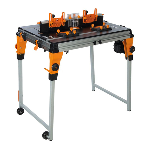
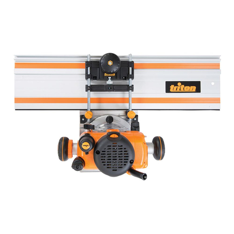
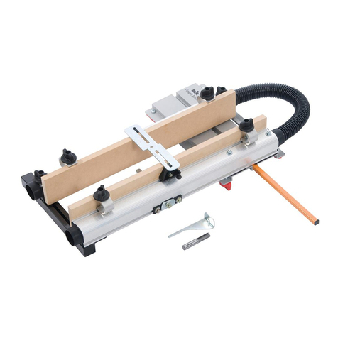
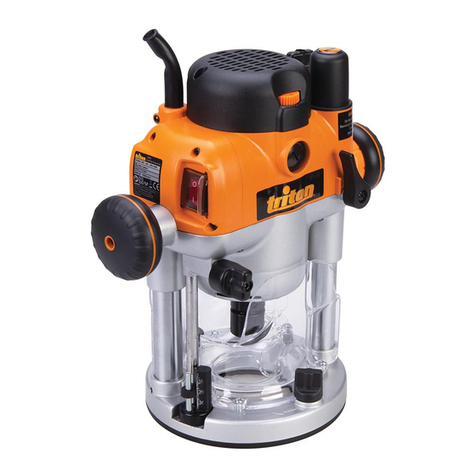
Triton RTA300 Quick guide

www.tritontools.com
Precision Router Table
RTA 300
Operating and
Safety Instructions
Bedienings- en
veiligheidsvoorschriften
Instructions d’utilisation et
consignes de sécurité
Gebrauchs- und
Sicherheitsanweisung
Istruzioni Per L’uso E
La Sicurezza
Instrucciones
de uso y de seguridad
PDF Compressor Pro

GB
CONTENTS
Thank you for purchasing this Triton tool. Please read these instructions: they contain information necessary for safe and
effective operation of this product. This product has a number of unique features and, even if you are familiar with similar
products, reading the instructions will help you get the full benefit of its unique design. Keep these instructions close to
hand and ensure all users of this tool have read and fully understand them.
Contents / Specifications / Symbols
Specifications 2
Symbols 2
Safety Instructions 3
Parts List 5
Product Images 6
Fitting the Table 9
Assembly 10
Key Factors for Quality of Cut 12
Operation 13
Edge Rebating 13
Trenching 14
Planing 16
Planing to Width 17
Edge Moulding 18
End Grain Work 19
Morticing 19
Warranty 20
SPECIFICATIONS
SYMBOLS
ENVIRONMENTAL PROTECTION
Waste electrical products should not be
disposed of with household waste.
Please recycle where facilities exist.
Check with your local authority or
retailer for recycling advice.
Always wear ear, eye and respiratory
protection.
WARNING. To reduce the
risk of injury, user must read instruction
manual
Instruction warning.
Part no: RTA300
Table size: 540mm x 690mm
Cuts: Planing, trenching, rebating, moulding, endgrain work,
free-hand work
Net weight: 12.5kg (27.5lb)
Protect your hearing
Always use proper hearing protection when tool noise exceeds 85dB.
PDF Compressor Pro

3
GB
Safety Instructions
WARNING Read all safety warnings and all
instructions. Failure to follow the warnings and
instructions may result in electric shock, fire and/
or serious injury.
Save all warnings and instructions for future
reference.
The term "power tool" in the warnings refers to
your mains-operated (corded) power tool or battery-
operated (cordless) power tool.
1) Work area safety
a) Keep work area clean and well lit. Cluttered or dark
areas invite accidents.
b) Do not operate power tools in explosive
atmospheres, such as in the presence of
flammable liquids, gases or dust. Power tools create
sparks which may ignite the dust or fumes.
c) Keep children and bystanders away while
operating a power tool. Distractions can cause you to
lose control.
2) Electrical safety
a) Power tool plugs must match the outlet. Never
modify the plug in any way. Do not use any adapter
plugs with earthed (grounded) power tools.
Unmodified plugs and matching outlets will reduce risk
of electric shock.
b) Avoid body contact with earthed or grounded
surfaces, such as pipes, radiators, ranges and
refrigerators. There is an increased risk of electric
shock if your body is earthed or grounded.
c) Do not expose power tools to rain or wet
conditions. Water entering a power tool will increase
the risk of electric shock.
d) Do not abuse the cord. Never use the cord for
carrying, pulling or unplugging the power tool.
Keep cord away from heat, oil, sharp edges or
moving parts. Damaged or entangled cords increase
the risk of electric shock.
e) When operating a power tool outdoors, use an
extension cord suitable for outdoor use. Use of
a cord suitable for outdoor use reduces the risk of
electric shock.
f) If operating a power tool in a damp location is
unavoidable, use a residual current device (RCD)
protected supply. Use of an RCD reduces the risk of
electric shock.
NOTE: The term “residual current device (RCD)” may
be replaced by the term “ground fault circuit interrupter
(GFCI)” or “earth leakage circuit breaker (ELCB)”.
3) Personal safety
a) Stay alert, watch what you are doing and use
common sense when operating a power tool. Do
not use a power tool while you are tired or under
the influence of drugs, alcohol or medication. A
moment of inattention while operating power tools may
result in serious personal injury.
b) Use personal protective equipment. Always wear
eye protection. Protective equipment such as dust
mask, non-skid safety shoes, hard hat, or hearing
protection used for appropriate conditions will reduce
personal injuries.
c) Prevent unintentional starting. Ensure the switch
is in the off-position before connecting to power
source and/or battery pack, picking up or carrying
the tool. Carrying power tools with your finger on the
switch or energising power tools that have the switch
on invites accidents.
d) Remove any adjusting key or wrench before
turning the power tool on. A wrench or a key left
attached to a rotating part of the power tool may result
in personal injury.
e) Do not overreach. Keep proper footing and balance
at all times. This enables better control of the power
tool in unexpected situations.
f) Dress properly. Do not wear loose clothing or
jewellery. Keep your hair, clothing and gloves away
from moving parts. Loose clothes, jewellery or long
hair can be caught in moving parts.
g) If devices are provided for the connection of dust
extraction and collection facilities, ensure these
are connected and properly used. Use of dust
collection can reduce dust-related hazards.
4) Power tool use and care
a) Do not force the power tool. Use the correct power
tool for your application. The correct power tool will
do the job better and safer at the rate for which it was
designed.
b) Do not use the power tool if the switch does not
turn it on and off. Any power tool that cannot be
controlled with the switch is dangerous and must be
repaired.
c) Disconnect the plug from the power source and/
or the battery pack from the power tool before
making any adjustments, changing accessories, or
storing power tools. Such preventive safety measures
reduce the risk of starting the power tool accidentally.
d) Store idle power tools out of the reach of children
and do not allow persons unfamiliar with the
power tool or these instructions to operate the
power tool.Power tools are dangerous in the hands of
untrained users.
SAFETY INSTRUCTIONS
PDF Compressor Pro

4
GB
e) Maintain power tools. Check for misalignment or
binding of moving parts, breakage of parts and
any other condition that may affect the power
tool’s operation. If damaged, have the power tool
repaired before use. Many accidents are caused by
poorly maintained power tools.
f) Keep cutting tools sharp and clean. Properly
maintained cutting tools with sharp cutting edges are
less likely to bind and are easier to control.
g) Use the power tool, accessories and tool bits etc.
in accordance with these instructions, taking into
account the working conditions and the work to
be performed. Use of the power tool for operations
different from those intended could result in a
hazardous situation.
5) Service
a) Have your power tool serviced by a qualified repair
person using only identical replacement parts.
This will ensure that the safety of the power tool is
maintained.
Safe use of the router table
Always follow these safety instructions when using
your router table
rotation arrows (printed around the central hole)
Workcentre or Router Stand, with the workpiece to the
left of the cutter
use the fence if using a cutter without a bearing or pilot
cutters
correctly adjusted changing or adjusting cutters
fence faces, the insert ring, the safety guard and the
workpiece before starting the router
operating to prevent them from vibrating into the cutter.
the day, or when leaving the unit unattended
Wear goggles
Wear ear defenders
Wear a respiratory mask
Wear protective clothing
Wear gloves
The tool must be used only for its prescribed purpose.
Any use other than those mentioned in this manual will
be considered a case of misuse. The user and not the
manufacturer shall be liable for any damage or injury
resulting from such cases of misuse.
The manufacturer shall not be liable for any
modifications made to the tool nor for any damage
resulting from such modifications.
Even when the tool is used as prescribed it is not
possible to eliminate all residual risk factors. The
following hazards may arise in connection with the
tool’s construction and design:
worn
worn
Safety Instructions
PDF Compressor Pro

5
GB
PARTS LIST
1. Router Table (1)
2. Vacuum Hose (1)
3. Protractor (1)
Fastener Bag 1 Contents
4. Tapered Hose Adaptor (1)
5. Series 2000 Workcentre Locking Hook (1)
6. M4 x 35mm Countersunk Screw (1)
7. M4 Hex Nut (1)
8. Small Insert Ring (1)
9. Large Insert Ring (1)
10. Alignment Tool (1)
Router Plate Components
11. Router Plate (1)
12. Sub Plate (1)
Fastener Bag 2 Contents
13. Plate Clamp Base (4)
14. Plate Clamp Knob (4)
15. M6 x 45mm Countersunk Screw (4)
16. M6 Flange Nut (12)
17. M6 x 60mm Coach Bolt (4)
18. M6 X 16mm Countersunk Screw (4)
19. Plate Spacer (4)
20. Washer (4)
21. Clamp (4)
22. Clamp Base (4)
23. Clamp Spring (4)
24. Clamp Knob (4)
Sliding Table Insert Components
25. Sliding Table Insert (1)
Fastener Bag 3 (Sliding Table) Contents
26. Inner Bearing (2)
27. Inner Clamp Knob (2)
28. Outer Bearing (2)
29. Hold-Down (1)
30. M6 X 45mm Countersunk Screw (2)
31. M6 X 20mm Countersunk Screw (3)
32. M6 Flange Nut (2)
33. M6 Hex Nut (3)
Fence Components
34. Fence (1)
35. MDF Fence Face (2)
36. Rear Guard (1)
37. Front Guard (1)
Fastener Bag 4 (Fence) Contents
38. Fence Bracket (2)
39. M4 Nyloc Nut (10)
40. M4 X 25mm Countersunk Screw (2)
41. 1.5mm Shim (2)
42. 1.0mm Shim (2)
43. Micro Adjuster (2)
44. M4 X 45mm Countersunk Screw (8)
45. Fence Springs (8)
46. Fence Spring Base (4)
47. Fence Spring Plate (4)
Pressure Finger Components
48. Straight Finger (2)
49. Bent Finger (2)
50. Spacer (2)
51. Plastic Washer (4)
52. Finger Post (4)
Parts List
PDF Compressor Pro

6
GB
Product Images
24
2021
23
32 22
17
10
Fig.7
Fig.8
Fig.9
Fig.6
16
16
14
13
19
15
11
18 8 9
12
PRODUCT IMAGES
GB
PDF Compressor Pro

7
GB
Product Images
Fig. 11
4
2
41
43 39
46
45
47
52
36
37
50
38
51
40
44 35
39
49
34
42
Fig. 10
27
16
26
15
33
28
31
31
25 33
29
PDF Compressor Pro

8
GB
Product Images
Fig. 12
3
48
51
25
52
11
10
8
9
1
Fig. 13
48
51
1
50
52
PDF Compressor Pro

9
GB
Fitting the Table
FITTING THE TABLE
Fitting to a Triton Series 2000 Workcentre
See Figs 1 - 3
1. Fit the Series 2000 Workcentre Locking Hook (5) to the
front bearing channel of the
Router Table (1) using the M4
x 35mm Countersunk Screw
(6) and M4 Hex Nut (7)
2. Locate the hook into the slot
in the front end panel of the
Workcentre and lower the
rear of the table onto the
Workcentre (Fig 2)
3. Rotate the rear locking
latches on the router table as
necessary so that they are
at right angles to the table,
with the latch bars (on the
underside of latches) outside
the table
4. This will allow the rear of
the table to sit flat on the
Workcentre bearing channels
5. Secure the table in position by
rotating the latches to engage
the bearing channels (Fig 3)
Fitting to a Triton MK3 Workcentre
See Fig 4
1. Place the Router Table (1)
behind the front end panel of
the Workcentre and rest it on
the bearing channels
2. Align the keyholes in the front
end panel of the Workcentre
with those in the front bearing
channel of the router table
and use the MK3 table locking pins to lock the table in
position
3. Secure the table as described above in steps 3 - 5 of
‘Fitting to a Triton Series 2000 Workcentre’ (Fig 3)
Fitting to a Triton Router Stand
See Fig 5
1. Fit the Router Table (1) over
the front end panel of the
router stand with the conical
pins (on the router stand)
locating into the holes on
the inside face of the front
bearing channel of the table
2. Rotate the rear locking latches on the router table as
necessary so that they are at right angles to the table,
with the latch bars (on the underside of the latches)
outside the table
3. Lower the rear end of the table onto the stand
4. Secure in position by rotating the latches to engage the
bearing channels on the stand
Router Stand RSA300 Accessories
Stand RSA300; these snap onto the lower tubes of the
stand
table fence - it hangs via the scale pointer holes.
Theses hooks should be fitted to the right hand side of
the stand viewed from the switchbox end)
finger assembly, which hangs via the finger slots.
These hooks should be fitted on the left side
storage of the Protractor (3). For a tight fit, bend the tab
in the top of the hole downward slightly
Fig.1
Fig.2
Fig.3
Fig.4
Fig.5
PDF Compressor Pro

10
GB
Assembly
ASSEMBLY
Assembling the router plate
See Fig 6
1. Fit the Clamp Bases (13) to the corners of the underside
of the Router Plate (11) with the M6 x 45 Countersunk
Screws (15) and M6 Flange Nuts (16). Do not tighten
yet
2. Fit the sub plate to the router plate using the M6 x 16
Countersunk Screws (18), Plate Spacers (19) and M6
Flange Nuts (32). Tighten firmly
3. Fit the Small Insert Ring (8) into the router plate. It twist
locks into position
4. Sit the router plate into the central cut-out in the table
(clamp bases facing down) with the depressed slot in
the plate on the left (when viewed from the switchbox
end)
5. Slide the clamp bases outward until they locate
against the square tube supports, ensuring there is no
movement in the plate, then tighten firmly in position
6. Screw the Plate Clamp Knobs (14) onto the screws until
they hold the router plate firmly into the table (they cut
their own thread)
In use:
aways are facing outward, the plate can be removed;
turn the knobs clockwise about half a turn to tighten it
back down
while fitting the router
Fitting a Triton router to the sub plate
See Figs 7 & 8
mounting of Triton Routers
1. Loosen the two mounting knobs on your router until
they are approximately 10mm (3⁄8") above the base of
the router
2. Locate the router onto the sub plate with the chuck
plunged through the small insert ring. Align the
mounting knobs with the small round holes
3. Push down on the mounting knobs until the bolt heads
locate into the keyholes and rotate the router anti-
clockwise until the knobs align with the small triangle
holes
4. Tighten the mounting knobs firmly
Fitting other brands of router to the sub plate
See Fig 9
1. Lock your router at full depth and fit the Router
Alignment Tool (10) into the collet. Place the router onto
the Sub Plate (12) with the alignment tool fitting snugly
through the small insert ring. NOTE: Most large routers
fit best with their handles angled diagonally across the
plate
2. Determine the four most suitable clamp slots –
ensuring you do not obstruct any of the router controls.
If four suitable clamping positions cannot be achieved,
three well spaced clamps are acceptable. Alternatively,
remove the obstruction (eg. turret) from the router, or
attempt to straddle the clamp over it
3. Locate the heads of the M6 x 60 Coach Bolts (17) into
the openings of these slots and loosely assemble the
Clamp Bases (22) onto them using M6 Flange Nuts (32)
4. Slide the clamp bases up against the base of the router
and tighten the flange nuts with a 10mm spanner
5. Fit the Clamp Springs (23), Clamps (21) then Washers
(20) over the bolts and loosely fit the Clamp Knobs (24)
6. Determine which end of the clamps best suits your
router base, then slide them over a free position on the
base
7. Tighten the clamp knobs firmly
slide back the clamps to disengage them from the
router base
direct screw mounting of Porter Cable routers to the
sub plate via their base mounting screws, if preferred
Assembling the sliding table insert
See Fig 10
1. Tighten the Outer Bearings (28) and Hold-down (29)
onto the Sliding Table Insert (25) using the M6 x 20
Screws (31) and M6 Hex Nuts (33)
2. Fit the Inner Bearings (26) to the insert using the M6
x 45 Screws (30) and M6 Flange Nuts (32). Do not
tighten yet
3. Locate the insert into the tracks in the table by hooking
the hold-down under the outer (orange) track first.
The slots on the inner bearings should locate onto the
flange on the aluminium inner track
4. Now firmly tighten the inner bearing screws and check
that the insert slides smoothly
5. If there is any movement between the aluminium inner
track and the inner bearings, loosen the screws, twist
the bearing slightly and re-tighten
PDF Compressor Pro

11
GB
Assembly
6. Screw the Inner Clamp Knobs (27) onto the inner
bearing screws; they cut their own thread
In use:
modes of use. When the cut-away edges are facing
the inner track the insert is free to slide and can be
removed
away edges facing inwards, the insert is locked from
sliding. By backing off the clamps one complete turn,
the insert is free to slide but cannot be removed
table surface and if necessary loosen the three screws
securing the aluminium inner track and make any
required adjustment before re-tightening
Assembling the fence
See Fig 11
1. Fit the Rear Guard (36) to the Fence (34) by inserting
the front tabs first. Slide the red locking tab up then
lower the rear of the guard while depressing the rear
catch
2. When the catch snaps into place, slide the locking tab
down to lock the guard in position
3. Attach the MDF Fence Faces (35) using the M4 x 45
Countersunk Screws (44) via the long slots in the fence
4. Position them with the two extra holes at the top.
Fit the Fence Spring Plates (47) (with their flat faces
against the fence), Fence Springs (45) and Fence
Spring Bases (46) onto the bolts at the rear of the fence
and tighten into position using M4 Nyloc Nuts (39)
5. Tension the nuts so that the MDF holds securely
against the fence
In use
the cutter as possible. Position them by sliding forward
or backward
unwanted movement. For very heavy or difficult cuts
lock the faces by fully tightening the screws
MDF Fence Faces using the M4 x 25 Countersunk
Screws (40) and M4 Nyloc Nuts (39)
guard. Some initial force may be necessary. Loosen the
knob and slide the guard guide forward until the front
guard can be fully lowered and the guard slides against
the MDF, then tighten
via the T-bolts through the table slots. The T-bolts are
designed to pass through the table slots and then be
turned through 90°, locking the fence to the table when
the knobs are tightened
Check Fence Squareness
See Fig 14
1. Use a set square against the face of the fence to
check it is square to the table. If necessary loosen the
horizontal locking screws through the rear flange of
the fence and adjust the vertical jacking screws in the
braces until the fence is square, then re-tighten the
locking screws
2. Adjust the two front braces together then the two rear
braces together
Storage hints
notches at the rear of the fence
storage position when not in use (see Fig 10). When in
use, they relocate to the slots behind the fence
(see Fig. 18)
the fence braces when not in use (see Fig. 10). When
in use, they are fitted behind the MDF fence faces
(see Figs. 25 & 26). If necessary loosen off the fence
springs to accommodate fitting of the shims, then re-
tighten to the desired tension
Assembling the pressure fingers
See Figs 12 & 13
1. Insert two Finger Posts (52) with Spacers (50) through
the holes in the fence brackets and fit the Plastic
Washers (51)
2. Insert the Bent Pressure Fingers (49) through the slots
and tighten the knobs on top of the finger posts to
tension them into position
3. Insert the remaining two finger posts through the
preferred holes in the sliding insert, then fit the
washers and Straight Fingers (48) before tightening
to the holes in the table for operations such as ‘Planing
to Width’. The finger post spacers should be reversed
when fitting to the table
interchangeable depending on the operation you are
performing
Fig.14
PDF Compressor Pro

12
GB
Assembly / Key Factors for Quality of Cut
Adjusting the protractor
See Figs 12 & 15
1. Fit the Protractor (3) to the preferred holes in the MDF
slider and tighten the small knobs on the locating
bosses until they are a snug fit. If the knobs are too
tight to turn by hand a small spanner can be used.
2. With the knobs fully tightened the protractor cannot be
removed (Fig 12)
Checking the protractor scale
1. Loosen the adjustment knob and line the edge of the
protractor up with the aluminium inner track
2. Check that the scale pointer is at 90°. If necessary,
loosen the central clamping screw and adjust the
position of the metal scale plate until it reads 90°
(Fig 15)
In use:
in the MDF slider. In most cases the protractor will be
used following the workpiece
protractor to support the workpiece close to the cutter.
By also trimming the wooden face as it passes the
cutter, tear-out in the workpiece will be prevented
allow re-trimming
Fig.15
KEY FACTORS FOR QUALITY OF CUT
The quality of cut using a router depends on a number of
key factors.
The Feed Rate
the motor, cutter size and type, depth and width of cut,
and the type of material
overload. Cutting will be difficult to control, and tear
out (splintering) is likely. Damage may occur to your
router motor or chuck, and in extreme cases the cutter
could break
the bit to rub instead of cutting. This will show up as
burn marks on your workpiece
quality, and the sound of the router motor are guides to
the correct feed rate
slight burn mark or step in your work
off to ensure that you can complete the cut smoothly
without obstruction
Depth of Cut
As a general rule:
3⁄8" in
diameter) ensure that the depth of cut does not exceed
the diameter of the bit
two or three shallow cuts rather than one deep cut
Router bit selection
18,000 and 24,000 rpm (min-1)
marks and tearout
they generally do not retain their sharp edges for long
tipped router cutters. Tungsten carbide is the hardest
commercially available cutting edge material
which have a ball bearing pilot on top. Bits which have
an integral pilot (i.e. no ball bearing race) can burn or
mark the work
PDF Compressor Pro

13
GB
OPERATION
Introduction
See Fig 16
reference only. They do not relate to any actual
dimensions, which are determined by the diameter of
the cutter used
have to be locked parallel on the table. The readings in
both fence windows may differ
pressure fingers. When they cannot be used ensure the
workpiece is pressed down on the table and against
the fence during the cut
material you will be working with, to ensure the desired
cut is achieved
components, slide the MDF fence faces toward each
other until they just clear the cutter. This provides
maximum support for the workpiece, close to the cutter
(Fig 16) diameter and less than 50mm (approx. 2") replace the
small table insert with the larger size
permanently lock on, use tape or a releasable cable tie
to hold the switch on during operation. Alternatively a
trigger strap (part no. AGA001) can be ordered through
your local Triton stockist
Dust extraction
highly recommended
vacuum cleaner, domestic (bag-type) units can fill
up very quickly. For a much larger capacity, consider
fitting a Triton Dust Collector (DCA300) to your vacuum
cleaner
overhead guard and screw the Tapered Hose Adaptor
(4) onto the opposite end of the hose. Note that it has a
left-handed thread
cleaner into the tapered hose adaptor
If doing so, using the larger diameter table insert will
help wood shavings to fall beneath the table Ensure
shavings do not build-up between the fences and your
workpiece. Brush or blow away accumulated shavings
after every few cuts, when the cutter has stopped
spinning completely.
vacuum cleaner may exceed the rated amperage of
your domestic extension lead or power outlet; always
connect your vacuum cleaner and router to separate
electrical outlets, and switch on both appliances
separately
EDGE REBATING
See Figs 17 & 18
cutter. If using a bearing guided rebate cutter, refer to
‘Edge Moulding’
1. Start by setting the router fence flush with the cutter
2. Use a wooden straight edge along the fence face
and rotate the cutter until its cutting edge is in the
outermost position
3. Adjust the fence until the front and rear scale readings
are similar and the straight edge is touching the cutter,
then lock the fence
(eg. a cabinet backing), use an offcut of that
component to set up the cut as follows:
1. Set and lock the router fence flush with the cutter
2. Install the micro-adjusters in the table slot behind the
fence but do not yet tighten them into position
3. Place your offcut between the back flange of the fence
and the micro-adjusters then tighten them into position
(Fig 18)
4. Remove the offcut, re-position the fence back against
the micro-adjusters and lock it
scales as a reference or use the micro-adjusters as
follows:
1. Set the router fence flush with the cutter
2. Screw the thumbwheels on the micro-adjusters out to
provide sufficient adjustment
Fig.16
Key Factors for Quality of Cut / Edge Rebating
PDF Compressor Pro

14
GB
3. Tighten the micro-adjusters in position against the rear
of the fence and screw the thumbwheels in to obtain
the required rebate amount. One complete turn is
1.0mm and calibrations are marked every 0.2mm. (1⁄32"
= 0.8mm, 1⁄16" = 1.6mm, 1⁄8" = 3.2mm, 1⁄4" = 6.4mm)
4. Unlock the fence, move it back against the micro-
adjusters and re-lock
5. For short edges, the fence should only be used to
set the rebate depth; use the protractor to guide the
workpiece (See ‘Cross-trenching’). The fence must be
set exactly parallel for this operation
TRENCHING
WARNING: For many trenching operations, the cutter
cannot be guarded. Keep your hands well clear and never
trail your fingers behind the workpiece
Trenching against a fence
See Figs 19 & 20
workpiece, the router table fence can be used
Workcentre, trenches up to 610mm (24") in from an
edge can be performed against the rip fence
achieved on any model of Triton Extension Table when
the Router Table is fitted to a Workcentre
If using a Triton Router Stand RSA 300, you may
consider the optional Mini Sliding Extension Table
(ETA100) used in ‘Fixed Rip’ mode. The compact design
fits quickly to the new stand and makes many difficult
cuts easy
see ‘Using a planing jig’
your fence at the required setting. Feed the workpiece
smoothly through the cutter and against the fence,
whilst keeping it pressed down evenly against the table
Fig.17
Fig.18
Fig.19
Fig.20
Edge Rebating / Trenching
PDF Compressor Pro

15
GB
Cross-trenching
See Figs 21 - 23
performed with the protractor following the workpiece
keyholes in the face of the protractor and extend it past
the cutter
notch and to prevent tear-out in the workpiece (Fig 21)
performed in the overhead mode on the Workcentre
using the optional Router & Jigsaw Mounting Plate
(AJA150) (Fig 22)
Extension Table in the ‘Panel Saw’ mode. Clamp an
extended wooden batten in front of the rip fence using
the hold-down clamps and run it through the cutter to
provide a sighting notch and prevent tear-out (Fig 23)
Stopped Cross-trenches
See Fig 24
by placing suitable length spacer boards in front and
behind the slider to limit its travel
Table by fitting stops (eg hose or exhaust clamps) to the
inner track to limit the table travel
the work to be plunged onto the cutter. While this
can be achieved using the above methods, it is best
performed in the overhead mode on the Workcentre
using the optional Router & Jigsaw Mounting Plate
(AJA150)
workpiece back with the router still running. Switch it
off and wait for the cutter to stop spinning
Fig.21
Fig.22
Fig.23
Fig.24
Trenching
PDF Compressor Pro

16
GB
PLANING
mostly hidden behind the fence faces
WARNING: NEVER make planing cuts with the
workpiece passing between the cutter and fence on the
right. The cutter will flex aside, ‘climb up’ on the work,
and rip the workpiece out of your hands - or pull your
hand into the cutter
Planing on the router fence
See Figs 25 & 26
using combinations of the 1.0 & 1.5mm planing shims
supplied
cuts
and slot the shims into the gap created, straddling each
set of screws (loosen spring tension if necessary)
shims behind the rear MDF fence face
MDF fence face and the 1.0mm shims behind the front
MDF fence face
with the rear MDF fence face (Fig 26), then begin your
cut
Planing a high face on the router fence
See figs 27a & b
the guard guide back behind the fence. The pressure
finger assemblies must also be removed from the fence
1. For 1.0 & 1.5mm cuts, insert the appropriate shims
behind the rear MDF fence face
2. Lock the fence with the rear face aligned with the
cutter
3. Remove the shims and, without re-adjusting the fence,
complete the first pass (Fig 27a)
4. Re-fit the shims behind the rear MDF fence face, then
flip the workpiece and complete the second pass
(Fig 27b)
0.5mm shims behind the rear MDF fence face
Fig.25
Fig.26
Fig.27a
Fig.27b
Planing
PDF Compressor Pro

17
GB
PLANING TO WIDTH
relocate the safety guard onto the router plate
their furthest setting. Lift the red lock tab at the rear
and depress the catch to remove the guard from the
fence, then re-fit it to the table. Reposition the front
guard back until it is flush against the rear guard
spacers reversed, as described in ‘Assembling the
pressure fingers’ (Fig. 13)
left side of the cutter (viewed from the switchbox end),
therefore a Series 2000 Workcentre, Extension Table or
planing jig is required – see guidance for each below
than 3mm (1⁄8") with each pass
Using the Series 2000 Workcentre fence
See Fig 28
and the scale readings are the same front and rear.
Subtract this scale reading from your desired planing
width to obtain the required fence setting
blade and rip fence and adjust the fence until the
scale readings are approximately equal front and rear.
Remove the workpiece, reset the fence toward the
cutter by the desired planing amount and commence
your cut
Using an extension table fence
See Fig 29
to a width
extension table fence; narrower workpieces will require
a spacer board between the fence and the workpiece and measure the distance between the cutter and the
fence
desired planing width
cutter and the fence and adjust the fence until the
scale readings are approximately equal front and rear.
Remove the workpiece, reset the fence toward the
cutter by the desired planing amount and start your cut
Using a planing jig
See Figs 30 & 31
1. To make a planing jig, cut two boards from 19mm sheet
material to fit perfectly within the table slider opening
2. Rebate the edges of one board (the base board) to
accommodate the slider tracks and ensure the jig sits
flush with the table
3. With the router fence set at maximum width, make a
slot in the base board using a 1⁄2" (12mm) dia. straight
bit. Slot a little over half way through the board then flip
it and make a second slot in the same face
4. Use the same method to make slots in the other board,
but this time using a 1⁄4" (6mm) dia. bit
Fig.28
Fig.29
Fig.30
Planing to Width
PDF Compressor Pro

18
GB
5. Fit the jig base to the table and use the router fence
clamping knobs and T-bolts to join the top to it
6. The full range of adjustment can be achieved by
rotating the jig base and/or the jig top
7. Place the workpiece between the cutter and the jig and
lock the jig
8. Remove the workpiece and reset the jig top towards
the cutter by the desired planing amount
micro adjusters in the jig slots to set the width, either
by using the thumbwheels or the fence shims, as
described in ‘Planing’
the jig fence can be replaced with a narrow batten
(Fig 31)
EDGE MOULDING
plain pilot on top, which can be used without a fence.
However, straight sided or slightly convex workpieces
are more easily edge moulded using the fence
fit the guard to the router plate
Using the router fence
See Fig 32
It is always best to use two or three shallow passes rather
than one deep pass to lessen the chance of tearout or
splintering
Adjust the fence to just expose the cutter for the first
pass. Progressively expose more of the cutter by adjusting
the fence between passes until the final pass when the
pilot should be level with the fence
For extra support and guidance, short edges are best
performed against the protractor (see ‘End Grain Work’
below)
Free-hand edge moulding
See Fig 33
WARNING: Never attempt free-hand routing without a
bearing or pilot guided cutter
integral lead-in and trail-out guides also make the job
much easier
1. Several passes are better than one deep pass. Start
with the cutter lowered and progressively increase the
cutter height for each pass
2. Rest the workpiece against the front (lead-in) edge of
the guard and maintain this contact while feeding the
workpiece onto the cutter
3. Continue the cut against the cutter’s pilot guide
4. Near the end of the cut, swing the workpiece toward
the rear (trail-out) edge of the guard
5. Complete the cut with the work in contact with the rear
edge of the guard
Fig.31
Fig.32
Fig.33
Planing to Width / Edge Moulding
PDF Compressor Pro

19
GB
END GRAIN WORK
controlled against the router fence and can often tear-
out at the completion of the cut. This can be overcome
by using the protractor fitted with an extended wooden
face as described in ‘Cross-trenching’
with the fence fitted (see ‘Edge Rebating’), or with the
guard fitted to the router plate (Fig 34)
Using a template guide
See Fig 35
possible. If the guard cannot be fitted, due to the nature
of the cut, take great care with your hand positions edges of curved or shaped components
top bearing (as used for laminate trimming)
should be re-located to the router plate
1. First, rough out the shape of the workpiece with a
jigsaw
2. Then, using tacks or double-sided tape, attach the
template to the top of your workpiece
3. Set the height of the flush trim bit so that the bearing
runs only along the template. The workpiece will then
finish exactly the same size as the template
4. Feed against the direction of rotation, keeping both
hands on top of the workpiece and well clear of the
cutter
MORTICING
WARNING: The cutter cannot be fully guarded when
morticing so ensure your hands are well clear of the cutter
at all times and hold the workpiece firmly.
withyour saw in the Workcentre.
downfinger assemblies to be removed from the fence,
and the guard guide adjusted back behind the face of
the fence
workpiece will be in approximately the right position
above the cutter
your workpiece onto the cutter
perform several cuts at increasing settings
distance. The cutter will tend to push the material away
from the fence, so firm sideways pressure against the
fence is necessary
hold the workpiece against the fence
until satisfied with the position of the mortice
best to work between two stop blocks clamped to the
fence. If the workpieces are too long to use stop blocks
fitted to the fence, replace the MDF faces with longer
ones and fit the blocks to them (Fig. 36)
possible to work between stop blocks) reference the
mortice position by drawing lines on the side of your
workpiece and aligning these with pencil lines drawn
onto the table to indicate the position of your cutter
TIP: For finishing, it is easier to round off the tenons
rather than chiselling the mortices square at the ends.
Fig.34
Fig.35
End Grain Work / Morticing
PDF Compressor Pro

20
GB
Triton Precision Power Tools guarantees to the
purchaser of this product that if any part proves to
be defective due to faulty materials or workmanship
within 12 MONTHS from the date of original
purchase, Triton will repair, or at its discretion
replace, the faulty part free of charge.
This guarantee does not apply to commercial use
nor does it extend to normal wear and tear or
damage as a result of accident, abuse or misuse.
* Register online within 30 days.
Terms & conditions apply.
This does not affect your statutory rights
To register your guarantee visit our web site at
www.tritontools.com* and enter your details.
indicated otherwise) for information on future releases.
Details provided will not be made available to any third party.
PURCHASE RECORD
Date of Purchase: ___ / ___ / ____
Model: RTA300
Serial Number: __________________
Retain your receipt as proof of purchase
WARRANTY
Warranty
PDF Compressor Pro
Other manuals for RTA300
1
Table of contents
Languages:
Other Triton Power Tools manuals

Triton
Triton TRA001 Quick guide

Triton
Triton TRA001 Quick guide

Triton
Triton TDJ 600 User manual

Triton
Triton TWSS10 Quick guide

Triton
Triton T12OT Quick guide

Triton
Triton TJS 001 Assembly instructions

Triton
Triton TMUTL Assembly instructions

Triton
Triton XT18 User manual

Triton
Triton TRA001 Quick guide

Triton
Triton TSPS450 User manual

Triton
Triton TRA001 Quick guide

Triton
Triton TWX7RT001 User manual

Triton
Triton mof001 Quick guide

Triton
Triton TRTA001 Quick guide

Triton
Triton TWSS10 Quick guide

Triton
Triton TW SS10 Quick guide

Triton
Triton JOF001 Quick guide

Triton
Triton Superjaws XXL Quick guide

Triton
Triton EPA 001 Quick guide

Triton
Triton TDJ 600 Quick guide