Trix BR 50 User manual

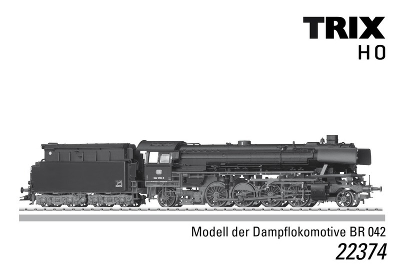
Modell der Dampflokomotive BR 50
22785
F
D GB USA NL

2

3
Inhaltsverzeichnis: Seite
Informationen zum Vorbild 4
Sicherheitshinweise 6
Wichtige Hinweise 6
Multiprotokollbetrieb 6
Hinweise zum Digitalbetrieb 7
Schaltbare Funktionen 9
Parameter/Register 10
Wartung und Instandhaltung 26
Ersatzteile 36
Table of Contents: Page
Information about the prototype 4
Safety Notes 11
Important Notes 11
Multi-Protocol Operation 11
Notes on digital operation 12
Controllable Functions 14
Parameter/Register 15
Service and maintenance 26
Spare Parts 36
Sommaire : Page
Informations concernant la locomotive réelle 5
Remarques importantes sur la sécurité 16
Information importante 16
Mode multiprotocole 16
Remarques relatives au fonctionnement
en mode digital 17
Fonctions commutables 19
Paramètre/Registre 20
Entretien et maintien 26
Pièces de rechange 36
Inhoudsopgave: Pagina
Informatie van het voorbeeld 5
Veiligheidsvoorschriften 21
Belangrijke aanwijzing 21
Multiprotocolbedrijf 21
Aanwijzingen voor digitale besturing 22
Schakelbare functies 24
Parameter/Register 25
Onderhoud en handhaving 26
Onderdelen 36

4
Informationen zum Vorbild
Als letzte sogenannte „Einheitsdampfloks“ entstanden kurz
vor Beginn des Zweiten Weltkriegs die Maschinen der Baurei-
he 50. Im April 1937 beauftragte das Reichsverkehrs-Ministeri-
um (RVM) das Reichsbahn-Zentralamt (RZA) mit dem Entwurf
einer leistungsfähigen Güterzuglokomotive für Nebenbahnen
unter anderem als Ersatz für die Eh2-Güterzugdampfloks der
Reihe 57.10-40 (preußische G 10). Sie sollte in der Ebene einen
mittelschweren Güterzug ziehen, Gleisbögen mit 140 m Halb-
messer befahren können und mit rund 15 t Radsatzfahrmasse
auch auf Nebenbahnen mit leichtem Oberbau problemlos
einsetzbar sein. Als Höchstgeschwindigkeit erschienen 80
km/h ausreichend. Da an vielen Endbahnhöfen entweder gar
keine Drehscheiben waren oder die vorhandenen zu kurz,
sollte die Maschine aber in beiden Richtungen gleich schnell
sein. Daher sah man für den Tender zum Schutz des Lokperso-
nals bei Rückwärtsfahrt eine Schutzwand vor. Das RZA plante
zunächst eine 1‘D-Lokomotive (Baureihe 46), weil man einer
1‘E weder die geforderte hohe Rückwärtsgeschwindigkeit
noch die erforderliche Zughakenleistung zutraute. Mit dieser
Maschine waren aber die geforderten Radsatzlasten nicht zu
erreichen und so blieb nur die Konstruktion eines Fünfkupplers
mit Vorlaufradsatz. Somit lieferte Henschel von April bis Juli
1939 die ersten zwölf Lokomotiven mit Stahlfeuerbüchse,
legiertem Stahl als Kesselbaustoff, einem Zweizylinder-Heiß-
dampftriebwerk mit Wagner-Überhitzer sowie 16 bar Kessel-
überdruck. Die so entstandene Baureihe 50 sollte alsbald die
glücklichste Konstruktion der Deutschen Reichsbahn werden,
denn die rund 1.600 PS starke und 80 km/h schnelle Maschine
entwickelte sich schnell zu einer universell einsetzbaren,
robusten und zuverlässigen Lokomotive.
Information about the prototype
The class 50 locomotive came into being shortly before the
start of World War II as the last of the so-called “standard
design steam locomotives”. In April of 1937 the Reich
Transportation Ministry (RVM) charged the German State
Railroad Central Office (RZA) with the design of a powerful
freight locomotive for branch lines, among other things, as
a replacement for the class 57.10-40 (Prussian G 10) 0-10-0
freight steam locomotives. It had to be able to pull a medium
weight train on flat terrain, negotiate curves with a radius of
140 meters / approximately 460 feet, and be usable with about
a 15 metric ton wheel load on branch lines with less than ideal
roadbed. A suitable maximum speed appeared to be 80 km/h
/ 50 mph. Since many end terminals had no turntable or one
that was too short, this locomotive had to be able to go at the
same speed in both directions. For that reason a protective
wall was planned for the tender to protect the locomotive
crew when running in reverse. The RZA initially planned a
2-8-0 locomotive (class 46) because no faith was placed in a
2-10-0 design for the required high speed in reverse and the
necessary tractive effort. The required wheel loads could not
be reached with a 2-8-0 design, so the design remained with
a locomotive with 5 driving axles and a pilot truck. From April
to July of 1939 Henschel delivered the first twelve locomo-
tives with a steel firebox, alloy steel for the boiler plating, a
two-cylinder, super heated steam running gear layout with a
Wagner super heater as well as 232 pounds per square inch
boiler excess pressure. The class 50 that came out of this was
soon destined to become the German State Railroad’s most
successful design, because this locomotive with its approxi-
mately 1,600 horsepower and 80 km/h / 50 mph speed quickly
became a general-purpose, sturdy, reliable unit.

5
Informations concernant la locomotive réelle
En tant que dernière «Locomotive à vapeur» dite «aux composants
partagés», c’est peu de temps avant le début de la deuxième guerre
mondiale que furent créées les machines de la Série 50. En avril
1937, le Ministère des transports du Reich (RVM) donna mission à
l’administration centrale de la Reichsbahn (RZA) de concevoir une
locomotive puissante pour trains de marchandises circulant sur des
lignes secondaires, entre autres en remplacement de la locomotive
à vapeur pour train de marchandises Eh2, de la Série 57.10-40 (G 10
prussienne). Elle devait tirer dans la plaine un train de marchan-
dises de poids moyen, être capable d’emprunter des voies courbes
d’un rayon de 140 m et pouvoir également être mise en œuvre sans
difficultés, avec une masse par essieu d’environ 15 t, sur des lignes
secondaires avec un matériel de voie léger. La vitesse maximale de
80 km/h apparut suffisante. Dans la mesure où dans de nombreuses
gares terminales, soit aucune plaque tournante n’était disponible,
soit celles-ci étaient trop courtes, la machine devait fonctionner à
la même vitesse dans les deux sens. C’est la raison pour laquelle
il fut prévu d’équiper le tender d’une paroi de protection en vue
de protéger le personnel de conduite de la locomotive au moment
de la marche arrière. L’administration centrale de la Reichsbahn
prévit tout d’abord une locomotive 1‘D (Série 46), car on doutait de
l’aptitude d’une la 1’E à garantir aussi bien la grande vitesse exigée
en marche arrière que la puissance nécessaire au crochet de
traction. Avec cette machine, les charges d’essieu exigées ne pou-
vaient toutefois pas être atteintes et c’est ainsi qu’il ne restait que la
possibilité de construire une locomotive à cinq essieux accouplés
avec essieu monté avant. La Série 50 ainsi créée allait ensuite deve-
nir la construction la plus heureuse de la Deutsche Reichsbahn, car
la machine qui développait environ 1.600 CV et qui avait une rapidité
d’environ 80 km/h est rapidement devenue une locomotive suscepti-
ble d’être mise en œuvre de manière universelle, robuste et fiable.
Informatie van het voorbeeld
De machines van de serie 50 ontstonden kort voor het begin van
de Tweede Wereldoorlog als laatste zogenaamde “eenheids-
stoomlocs”. In april 1937 ontving het Reichsbahn-Zentralamt
(RZA) van het Reichsverkehrs-Ministerium (RVM) de opdracht
om een krachtige goederenlocomotief voor nevenlijnen te ont-
werpen. Deze moest onder andere de Eh2-goederenstoomlocs
van de serie 57.10-40 (Pruisische G 10) gaan vervangen. De
loc moest op het vlakke land een middelzware goederentrein
kunnen trekken, bogen met een straal van 140 m doorrijden en
met een belasting per as van ongeveer 15 ton ook probleemloos
inzetbaar zijn op nevenlijnen met een lichte bovenbouw. Een
maximumsnelheid van 80 km per uur zou voldoende zijn. Omdat
op veel kopstations ofwel helemaal geen draaischijven ofwel te
korte draaischijven aanwezig waren, moest de machine echter in
beide richtingen dezelfde snelheid kunnen ontwikkelen. Daarom
werd de tender van een wand voorzien, die het locpersoneel bij
het achteruitrijden bescherming moest bieden. Het RZA plande in
eerste instantie een 1‘D-locomotief (serie 46), omdat men een 1‘E
noch de vereiste achteruitrijsnelheid, noch het vereiste vermo-
gen aan de trekhaak toevertrouwde. Met deze machine was het
echter niet mogelijk om binnen de voorgeschreven belasting per
as te blijven, dus bleef alleen de constructie van een vijfvoudig
gekoppelde machine met vooras over. En zo leverde Henschel
van april tot juli 1939 de eerste twaalf locomotieven met stalen
vuurkist, een ketel van gelegeerd staal, een tweecilinder-over-
verhitteraandrijving met Wagner-oververhitter en een keteldruk
van 16 bar. De zon ontstane serie 50 zou al snel als de meest
succesvolle constructie van de Deutsche Reichsbahn worden,
want de 80 km per uur rijdende machine met een vermogen
van 1.600 pk ontwikkelde zich ras tot een universeel inzetbare,
onverwoestbare en betrouwbare locomotief.
6
Sicherheitshinweise
• DieLokdarfnurmiteinemdafürbestimmtenBetriebssys-
tem eingesetzt werden.
• Analogmax.15Volt=,digitalmax.22Volt~.
• DieLokdarfnurauseinerLeistungsquelleversorgt
werden.
• BeachtenSieunbedingtdieSicherheitshinweiseinder
Bedienungsanleitung zu Ihrem Betriebssystem.
• FürdenkonventionellenBetriebderLokmussdasAn-
schlussgleis entstört werden. Dazu ist das Entstörset
611 655 zu verwenden. Für Digitalbetrieb ist das Entstör-
set nicht geeignet.
• ACHTUNG! Funktionsbedingte scharfe Kanten und Spitzen.
• SetzenSiedasModellkeinerdirektenSonneneinstrah-
lung, starken Temperaturschwankungen oder hoher
Luftfeuchtigkeit aus.
Wichtige Hinweise
• DieBedienungsanleitungunddieVerpackungsind
Bestandteile des Produktes und müssen deshalb aufbe-
wahrt sowie bei Weitergabe des Produktes mitgegeben
werden.
• FürReparaturenoderErsatzteilewendenSiesichbittean
Ihren Trix-Fachhändler.
• GewährleistungundGarantiegemäßderbeiliegenden
Garantieurkunde.
• Entsorgung:www.maerklin.com/en/imprint.html
• DervolleFunktionsumfangistnurunterTrixSystems,
DCC und unter mfx verfügbar.
• Eingebaute,fahrtrichtungsabhängigeStirnbeleuchtung.
Im Digitalbetrieb schaltbar.
• BefahrbarerMindestradius360mm.
Multiprotokollbetrieb
Analogbetrieb
Der Decoder kann auch auf analogen Anlagen oder Gleis-
abschnitten betrieben werden. Der Decoder erkennt die
analoge Gleichspannung (DC) automatisch und passt sich
der analogen Gleisspannung an. Es sind alle Funktionen,
die unter mfx oder DCC für den Analogbetrieb eingestellt
wurden aktiv (siehe Digitalbetrieb).
Digitalbetrieb
Der Decoder ist ein Multiprotokolldecoder. Der Decoder
kannunterfolgendenDigital-Protokolleneingesetztwerden:
mfx oder DCC.
Das Digital-Protokoll mit den meisten Möglichkeiten ist das
höchstwertige Digital-Protokoll. Die Reihenfolge der Digital-
ProtokolleistinderWertungfallend:
Priorität1:mfx
Priorität2:DCC
Priorität3:DC
Hinweis: Wenn zwei oder mehr digital-Protokolle am
Gleis erkannt werden, wählt der Decoder automatisch das
höchstwertige Protokoll. Wird z.B. mfx und DCC erkannt,
wählt der Decoder mfx.

7
Hinweis: Beachten Sie, dass nicht alle Funktionen in allen
Digital-Protokollen möglich sind. Unter mfx und DCC können
einige Einstellungen von Funktionen, welche im Analog-
Betrieb wirksam sein sollen, vorgenommen werden.
Hinweise zum Digitalbetrieb
• DiegenaueVorgehensweisezumEinstellenderdiversen
Parameter entnehmen Sie bitte der Bedienungsanleitung
Ihrer Mehrzug-Zentrale.
• DieabWerkeingestelltenWertesindfürmfxgewählt,so
dass ein bestmöglichstes Fahrverhalten gewährleistet ist.
Für andere Betriebssysteme müssen gegebenenfalls
Anpassungen getätigt werden.
• DerBetriebmitgegenpoligerGleichspannungim
Bremsabschnitt ist mit der werkseitigen Einstellung
nicht möglich. Ist diese Eigenschaft gewünscht, so muss
auf den konventionellen Gleichstrombetrieb verzichtet
werden(CV29/Bit2=0).
mfx-Protokoll
Adressierung
• KeineAdresseerforderlich,jederDecodererhälteine
einmalige und eindeutige Kennung (UID).
• DerDecodermeldetsichaneinerCentralStationoder
Mobile Station mit seiner UID automatisch an.
• NameabWerk:50 1581 DB KAB
Programmierung
• DieEigenschaftenkönnenüberdiegrascheOberäche
der Central Station bzw. teilweise auch mit der Mobile
Station programmiert werden.
• EskönnenalleCongurationVariablen(CV)mehrfach
gelesen und programmiert werden.
• DieProgrammierungkannentwederaufdemHaupt-oder
dem Programmiergleis erfolgen.
• DieDefaulteinstellungen(Werkseinstellungen)können
wieder hergestellt werden.
• Funktionsmapping:FunktionenkönnenmitHilfeder
Central Station 60212 (eingeschränkt) und mit der Central
Station 60213/60214/60215 beliebigen Funktionstasten
zugeordnet werden (siehe Hilfe in der Central Station).

8
DCC-Protokoll
Adressierung
• MöglicheAdressen:Kurze,langeundTraktionsadresse
• Adressbereich:
1 – 127 (kurze Adresse, Traktionsadresse)
1 – 10239 (lange Adresse)
• JedeAdresseistmanuellprogrammierbar.
• KurzeoderlangeAdressewirdüberdieCVsausgewählt.
• EineangewandteTraktionsadressedeaktiviertdie
Standard-Adresse.
Programmierung
• DieEigenschaftenkönnenüberdieCongurationsVari-
ablen (CV) mehrfach geändert werden.
• DieCV-NummerunddieCV-Wertewerdendirekteinge-
geben.
• DieCVskönnenmehrfachgelesenundprogrammiert
werden (Programmierung auf dem Programmiergleis).
• DieCVskönnenbeliebigprogrammiertwerden.PoM
(Programmierung auf dem Hauptgleis PoM) ist nur bei
den in der CV-Tabelle gekennzeichneten CV möglich.
PoM muss von Ihrer Zentrale unterstützt werden (siehe
Bedienungsanleitung ihres Gerätes).
• DieDefaulteinstellungen(Werkseinstellungen)können
wieder hergestellt werden.
• 14bzw.28/126Fahrstufeneinstellbar.
Fahrstufen am Lokdecoder und am Steuergerät müssen
übereinstimmen, es sind sonst Fehlfunktionen möglich.
• AlleFunktionenkönnenentsprechenddemFunktions-
mapping geschaltet werden.
• WeitereInformation,sieheCV-TabelleDCC-Protokoll.
Es wird empfohlen, die Programmierungen grundsätzlich auf
dem Programmiergleis vorzunehmen.
Logische Funktionen
Anfahr-/Bremsverzögerung
• DieBeschleunigungs-undBremszeitkönnengetrennt
von einander eingestellt werden.
• DielogischeFunktionsabschaltungABVkannüberdas
Funktionsmapping auf jede beliebige Funktionstaste
gelegt werden.

9
Schaltbare Funktionen
Spitzensignal an Funktion f0 Funktion f0
Rauchgenerator * an Funktion 1 Funktion f1 Funktion f1
Geräusch:Betriebsgeräusch — Funktion 2 Funktion f2 Funktion f2
Geräusch:Pfeife — Funktion 3 Funktion f3 Funktion f3
ABV aus — Funktion 4 Funktion f4 Funktion f4
Geräusch:Bremsenquietschen — Funktion 5 Funktion f5 Funktion f5
Geräusch:Luftpumpe — Funktion 6 Funktion f6 Funktion f6
Geräusch:Rangierpff — Funktion 7 Funktion f7 Funktion f7
Geräusch:Dampfablassen — Funktion 8 Funktion f8 Funktion f8
Geräusch:Kohleschaufeln — — Funktion f9 Funktion f9
Geräusch:Schüttelrost — — Funktion f10 Funktion f10
Geräusch:Wasserpumpe — — Funktion f11 Funktion f11
Geräusch:Injektor — — Funktion f12 Funktion f12
Geräusch:Glocke — — Funktion f13 Funktion f13
Rangiergang — — Funktion f14 Funktion f14
STOP mobile station
15
f0 f8 f0f8
f0 - f3 f4 - f7
* Gehört nicht zum Lieferumfang.

10
CV Bedeutung Wert DCC ab Werk
1 Adresse 1 - 127 3
2 PoM Minimalgeschwindigkeit 0 - 255 10
3 PoM Anfahrverzögerung 0 - 255 15
4 PoM Bremsverzögerung 0 - 255 15
5 PoM Maximalgeschwindigkeit 0 - 255 220
8 Werkreset/Herstellerkennung 8 131
13 PoM Funktionen F1 - F8 im Analogbetrieb 0 - 255 1
14 PoM Funktionen F9 - F15 und Licht im Analogbetrieb 0 - 255 1
17 Erweiterte Adresse (oberer Teil) CV29,Bit5=1 192
18 Erweiterte Adresse (unterer Teil) CV29,Bit5=1 128
19 Traktionsadresse 0 - 255 0
21 PoM Funktionen F1 - F8 bei Traktion 0 - 255 0
22 PoM Funktionen F9 - F15 und Licht bei Traktion 0 - 255 0
29 PoM
Bit0:UmpolungFahrtrichtung
Bit1:AnzahlFahrstufen14oder28/128
Bit2:DCCBetriebmitBremsstrecke(keinAnalogbetriebmöglich)
Bit5:kurze/langeAdresse
0 / 1
0 / 2
0 / 4
0 / 32
0, 1, 2, 3, 4, 5, 6,
7, 32, 34, 35, 36,
37, 38, 39 6
63 PoM Lautstärke 0 - 255 255

11
travel. They can be turned on and off in digital operation.
• Minimumradiusforoperationis360mm/14-3/16“.
Multi-Protocol Operation
Analog Operation
This decoder can also be operated on analog layouts or ar-
eas of track that are analog. The decoder recognizes alter-
nating current (DC) and automatically adapts to the analog
track voltage. All functions that were set under mfx or DCC
for analog operation are active (see Digital Operation).
Digital Operation
The decoders are multi-protocol decoders. These decoders
canbeusedunderthefollowingdigitalprotocols:mfxorDCC.
The digital protocol with the most possibilities is the highest
order digital protocol. The sequence of digital protocols in
descendingorderis:
Priority1:mfx
Priority2:DCC
Priority3:DC
Note: If two or more digital protocols are recognized in the
track, the decoder automatically takes on the highest value
digital protocol.For example, if mfx & DCC are recognized,
the mfx digital protocol is taken on by the decoder.
Note: Please note that not all functions are possible in all
digital protocols. Several settings for functions, which are
supposed to be active in analog operation, can be done
under mfx and DCC.
Safety Notes
• Thislocomotiveisonlytobeusedwiththeoperating
system it is designed for.
• Analogmax.15voltsDC,digitalmax.22voltsAC.
• Thislocomotivemustneverbesuppliedwithpowerfrom
more than one power pack.
• Pleasemakenoteofthesafetynotesintheinstructions
for your operating system.
• Thefeedertrackmustbeequippedtopreventinter-
ference with radio and television reception, when the
locomotive is to be run in conventional operation. The
611 655 interference suppression set is to be used for this
purpose. The interference suppression set is not suitable
for digital operation.
• WARNING! Sharp edges and points required for operation.
• Donotexposethemodeltodirectsunlight,extreme
changes in temperature, or high humidity.
Important Notes
• Theoperatinginstructionsandthepackagingareacom-
ponent part of the product and must therefore be kept as
well as transferred along with the product to others.
• PleaseseeyourauthorizedTrixdealerforrepairsor
spare parts.
• Thewarrantycardincludedwiththisproductspecies
the warranty conditions.
• Disposing:www.maerklin.com/en/imprint.html
• ThefullrangeoffunctionsisonlyavailableunderTrix
Systems and under DCC and mfx.
• Built-inheadlightsthatchangeoverwiththedirectionof

12
Notes on digital operation
• Theoperatinginstructionsforyourcentralunitwillgive
you exact procedures for setting the different parame-
ters.
• Thevaluessetatthefactoryhavebeenselectedformfx
in order to guarantee the best possible running characte-
ristics.
Adjustments may have to be made for other operating
systems.
• Thesettingdoneatthefactorydoesnotpermitoperation
with opposite polarity DC power in the braking block.
If you want this characteristic, you must do without
conventionalDCpoweroperation(CV29/Bit2=0).
mfx Protocol
Addresses
• Noaddressisrequired;eachdecoderisgivenaone-
time, unique identifier (UID).
• ThedecoderautomaticallyregistersitselfonaCentral
Station or a Mobile Station with its UID.
• Namesetatthefactory:50 1581 DB KAB
Programming
• Thecharacteristicscanbeprogrammedusingthe
graphic screen on the Central Station or also partially
with the Mobile Station.
• AlloftheCongurationVariables(CV)canbereadand
programmed repeatedly.
• Theprogrammingcanbedoneeitheronthemaintrackor
the programming track.
• Thedefaultsettings(factorysettings)canbeproduced
repeatedly.
• Functionmapping:Functionscanbeassignedtoanyof
the function buttons with the help of the 60212 Central
Station (with limitations) and with the 60213/60214/60215
Central Station (See help section in the Central Station).

13
DCC Protocol
Addresses
• Possibleaddresses:short,long,andm.u.address
• Addressrange:
1 – 127 (short address, m.u. address)
1 – 10239 (long address)
• Everyaddresscanbeprogrammedmanually.
• AshortoralongaddressisselectedusingtheCVs.
• Amultipleunitaddressthatisbeinguseddeactivatesthe
standard address.
Programming
• Thecharacteristicscanbechangedrepeatedlyusingthe
Configuration Variables (CV).
• TheCVnumbersandtheCVvaluesareentereddirectly.
• TheCVscanbereadandprogrammedrepeatedly.(Pro-
gramming is done on the programming track.)
• TheCVscanbeprogrammed,asyoudesire.PoM(Pro-
gramming on the layout track) is only possible with those
CVs marked in the CV table. PoM must be supported
by your central controller (see the instructions for your
controller).
• Thedefaultsettings(factorysettings)canbeproduced
repeatedly.
• 14or28/126speedlevelscanbeset.
The speed levels on the locomotive decoder and on the
controllermustagreewitheachother;otherwise,you
may have malfunctions.
• Allofthefunctionscanbecontrolledaccordingtothe
function mapping (see CV description).
• SeetheCVdescriptionfortheDCCprotocolforadditional
information.
We recommend that in general programming should be
done on the programming track.
Logic Functions
Acceleration / Braking Delay
• Theaccelerationandbrakingtimescanbesetseparately
from each other.
• ThelogicalfunctionshutoffforABV(Acceleration/
Braking Delay) can be assigned to any function button by
means of function mapping.

14
Controllable Functions
Headlights on Function f0 Function f0
Smoke generator * on Function 1 Function f1 Function f1
Soundeffect:Operatingsounds — Function 2 Function f2 Function f2
Soundeffect:whistleblast — Function 3 Function f3 Function f3
ABV off — Function 4 Function f4 Function f4
Soundeffect:Squealingbrakes — Function 5 Function f5 Function f5
Soundeffect:Airpump — Function 6 Function f6 Function f6
Soundeffect:Switchingwhistle — Function 7 Function f7 Function f7
Soundeffect:Blowingoffsteam — Function 8 Function f8 Function f8
Soundeffect:Coalbeingshoveled — — Function f9 Function f9
Soundeffect:Rockergrate — — Function f10 Function f10
Soundeffect:Waterpump — — Function f11 Function f11
Soundeffect:Injector — — Function f12 Function f12
Soundeffect:Bell — — Function f13 Function f13
Low speed switching range — — Function f14 Function f14
STOP mobile station
15
f0 f8 f0f8
f0 - f3 f4 - f7
* Not included in delivery scope.

15
CV Discription DCC Value Factory-Set
1 Address 1 - 127 3
2 PoM Minimum Speed 0 - 255 10
3 PoM Acceleration delay 0 - 255 15
4 PoM Braking delay 0 - 255 15
5 PoM Maximum speed 0 - 255 220
8 Factory Reset / Manufacturer Recognition 8 131
13 PoM Functions F1 - F8 in analog operation 0 - 255 1
14 PoM Functions F9 - F15 and lights in analog operation 0 - 255 1
17 Extended address (upper part) CV29,Bit5=1 192
18 Extended address (lower part) CV29,Bit5=1 128
19 Multiple Unit Address 0 - 255 0
21 PoM Functions F1 - F8 on Multiple Unit 0 - 255 0
22 PoM Functions F9 - F15 and lights on Multiple Unit 0 - 255 0
29 PoM
Bit0:Reversingdirectionoftravel
Bit1:Numberofspeedlevels14or28/128
Bit2:DCCoperationwithabrakingarea(noanalogoperation
possible)
Bit5:short/longaddress
0 / 1
0 / 2
0 / 4
0 / 32
0, 1, 2, 3, 4, 5, 6,
7, 32, 34, 35, 36,
37, 38, 39 6
63 PoM Volume 0 - 255 255

16
Remarques importantes sur la sécurité
• Lalocomotivenepeutêtreutiliséequ‘aveclesystème
d‘exploitation indiqué.
• Analogiquemax.15Volt=,digitalmax.22Volt~.
• Lalocomotivenepeutpasêtrealimentéeélectriquement
par plus d‘une source de courant à la fois.
• Ilestimpératifdetenircomptedesremarquessurla
sécurité décrites dans le mode d‘emploi de votre système
d‘exploitation.
•
Pour l’exploitation de la locomotive en mode convention-
nel, la voie de raccordement doit être déparasitée. A cet
effet, utiliser le set de déparasitage réf. 611 655. Le set de
déparasitage ne convient pas pour l’exploitation en mode
numérique.
•
ATTENTION! Pointes et bords coupants lors du fonctionne-
ment du produit.
• Nepasexposerlemodèleàunensoleillementdirect,
à de fortes variations de température ou à un taux
d‘humidité important.
Information importante
• Lanoticed‘utilisationetl’emballagefontpartieintégrante
duproduit;ilsdoiventdoncêtreconservéset,lecas
échéant, transmis avec le produit.
• Pourtouteréparationouremplacementdepièces,adres-
sez vous à votre détaillant-spécialiste Trix.
• Garantielégaleetgarantiecontractuelleconformément
au certificat de garantie ci-joint.
• Elimination:www.maerklin.com/en/imprint.html
• L’intégralitédesfonctionsestdisponibleuniquementen
exploitation Trix Systems, DCC et mfx.
• Feuxdesignalisations‘inversantselonlesensdemar-
che;feuxcommutablesenexploitationdigital.
• Rayonminimald’inscriptionencourbe360mm.
Mode multiprotocole
Mode analogique
On peut aussi faire fonctionner le décodeur sur des instal-
lations ou des sections de voie analogiques. Le décodeur
identifie automatiquement la tension de voie analogique
(DC). Toutes les fonctions qui ont été paramétrée pour le
mode analogique sous mfx ou sous DCC sont actives (voir
mode numérique).
Mode numérique
Les décodeur sont des décodeur multiprotocole. Le
décodeur peut être utilisé avec les protocoles numériques
suivants:mfx,DCC
Le protocole numérique offrant les possibilités les plus
nombreuses est le protocole numérique à bit de poids
fort. La hiérarchisation des protocoles numériques est
descendante:
Priorité1:mfx
Priorité2:DCC
Priorité3:DC
Indication : Si deux ou plus de deux protocoles numériques
sont reconnus sur la voie, le décodeur choisit automatique-
ment le protocole numérique le plus significatif. Entre les
protocoles mfx & DCC par exemple, le décodeur choisira le
protocole numérique mfx.

17
Indication : remarquez que toutes les fonctions ne peuvent
pas être actionnées dans tous les protocoles numériques.
Sous mfx et sous DCC, il est possible de procéder à
quelques paramétrages de fonctions devant être actives
dans le cadre de l’exploitation analogique.
Remarques relatives au fonctionnement en mode digital
• Encequiconcernelaprocédurederéglagedesdivers
paramètres, veuillez vous référer au mode d‘emploi de
votre centrale de commande multitrain.
• Lesvaleursparamétréesd’usinesontchoisiespour
mfx de manière à garantir le meilleur comportement de
roulement possible.
Pour d’autres systèmes d’exploitation, ces valeurs dev-
ront éventuellement être adaptées.
• L’exploitationaveccourantcontinudepolaritéinverse
dans les sections de freinage n’est pas possible avec
le réglage d’usine. Si cette propriété est désirée, il faut
alors renoncer à l’exploitation conventionnelle en cou-
rantcontinu(CV29/Bit2=0).
Protocole mfx
Adressage
• Aucuneadressen’estnécessaire,ledécodeurreçoittou-
tefois une identification unique et non équivoque (UID).
• AvecsonUID,ledécodeurindiqueautomatiquement
à une station centrale ou à une station mobile qu’il est
connecté.
• Nomencodeeenusine:50 1581 DB KAB
Programmation
• Lescaractéristiquespeuventêtreprogramméespar
l’intermédiaire de la couche graphique de la station cen-
trale, voire en partie aussi au moyen de la station mobile.
• Touteslescongurationsvariables(CV)peuventêtrelues
etprogramméesdefaçonréitérée.
• Laprogrammationpeutêtreréaliséesoitsurlavoie
principale, soit sur la voie de programmation.
• Lesparamétragespardéfaut(paramétragesusine)
peuvent être rétablis.
• Mappagedesfonctions:lesfonctionspeuventêtre
affectées à de quelconques touches de fonction au
moyen de la station centrale (60212) (restreinte) et avec
la station centrale 60213/60214/60215 (voir Aide au niveau
de la station centrale).

18
Protocole DCC
Adressage
• Adressepossibles:Courtes,longuesetadressesdetraction
• Catégoried’adresse:
1 à 127 (adresses courtes, adresses de traction)
1 à 10239 (adresses longues)
• Chaqueadresseestprogrammablemanuellement.
• L’adressebrèveoulongueestchoisieparl’intermédiaire
des CVs.
• Uneadressedetractionutiliséedésactivel’adresse
standard.
Programmation
• Lescaractéristiquespeuventêtremodiéesdefaçon
réitérée par l’intermédiaire des variables de configuration
(CVs).
• Touteslescongurationsvariables(CV)peuventêtrelues
etprogramméesdefaçonréitérée.
• Laprogrammationpeutêtreréaliséesoitsurlavoie
principale, soit sur la voie de programmation.
• LesCVpeuventêtreprogramméeslibrement.LaPoM
(programmation sur la voie principale) est possible
uniquement pour les CV signalées dans le tableau des CV.
La PoM doit être prise en charge par votre centrale (voir
la notice d’utilisation de votre appareil).
• Lesparamétragespardéfaut(paramétragesusine)
peuvent être rétablis.
• 14voire28/126cransdemarchesontparamétrables.
Pour éviter tout dysfonctionnement, les crans de marche
sur le décodeur de loco doivent impérativement coïncider
avec ceux de l’appareil de commande.
• Touteslesfonctionspeuventêtrecommutéesenfonction
du mappage des fonctions (voir le descriptif des CVs).
• Pourtouteinformationcomplémentaire,voirletableau
des CVs, protocole DCC.
Il est recommandé, de réaliser la programmation, fonda-
mentalement, sur la voie de programmation.
Fonctions logiques
Temporisation d’accélération et de freinage (TAF)
• Lestempsd’accélérationetdefreinagepeuventêtre
définis indépendamment l’un de l’autre.
• LadésactivationdelafonctionlogiqueTAFpeutêtre
affectée à n’importe quelle touche de fonction via le
mappage de fonctions.

19
Fonctions commutables
Fanal éclairage activé Fonction f0 Fonction f0
Générateur de fumée * activé Fonction 1 Fonction f1 Fonction f1
Bruitage:Bruitd’exploitation — Fonction 2 Fonction f2 Fonction f2
Bruitage:sifet — Fonction 3 Fonction f3 Fonction f3
ABV, désactivé — Fonction 4 Fonction f4 Fonction f4
Bruitage:Grincementdefreins — Fonction 5 Fonction f5 Fonction f5
Bruitage:Compresseur — Fonction 6 Fonction f6 Fonction f6
Bruitage:Sifetpourmanœuvre — Fonction 7 Fonction f7 Fonction f7
Bruitage:Échappementdelavapeur — Fonction 8 Fonction f8 Fonction f8
Bruitage:Pelletageducharbon — — Fonction f9 Fonction f9
Bruitage:Grilleàsecousses — — Fonction f10 Fonction f10
Bruitage:Pompeàeau — — Fonction f11 Fonction f11
Bruitage:Injecteur — — Fonction f12 Fonction f12
Bruitage:Cloche — — Fonction f13 Fonction f13
Vitesse de manœuvre — — Fonction f14 Fonction f14
STOP mobile station
15
f0 f8 f0f8
f0 - f3 f4 - f7
* Ne fait pas partie de la fourniture.

20
CV Affectation DCC Valeur Parm. Usine
1 Adresse 1 - 127 3
2 PoM Vitesse minimale 0 - 255 10
3 PoM Temporisation d‘accélération 0 - 255 15
4 PoM Temporisation de freinage 0 - 255 15
5 PoM Vitesse maximale 0 - 255 220
8 Réinitialisation d’usine/identification du fabricant 8 131
13 PoM Fonctions F1 - F8 en mode analogique 0 - 255 1
14 PoM Fonctions F9 - F15 et éclairage en mode analogique 0 - 255 1
17 Adresse étendue (partie supérieure) CV29,Bit5=1 192
18 Adresse étendue (partie inférieure) CV29,Bit5=1 128
19 Adresse traction 0 - 255 0
21 PoM Fonctions F1 - F8 pour traction 0 - 255 0
22 PoM Fonctions F9 - F15 et éclairage traction 0 - 255 0
29 PoM
Bit0:Inversiondusensdemarche
Bit1:Nombredecransdemarche14ou28/128
Bit2:ExploitationDCCavecsectiondefreinage(exploitation
analogique impossible)
Bit5:Adressecourte/longue
0 / 1
0 / 2
0 / 4
0 / 32
0, 1, 2, 3, 4, 5, 6,
7, 32, 34, 35, 36,
37, 38, 39 6
63 PoM Volume 0 - 255 255
Other manuals for BR 50
3
Table of contents
Languages:
Other Trix Toy manuals

Trix
Trix Minitrix RAm Series User manual

Trix
Trix H0 BR 98.4 User manual

Trix
Trix Baureihe 290 (V90) User manual

Trix
Trix 5600 Series User manual

Trix
Trix Velaro User manual

Trix
Trix EL 10 User manual

Trix
Trix H0 BR 78 User manual

Trix
Trix Minitrix 12560 User manual

Trix
Trix Re 620 Series User manual

Trix
Trix KOF II User manual
Popular Toy manuals by other brands

Eduard
Eduard M4A3E8 manual

HQ Kites & Design
HQ Kites & Design Delta Rainbow owner's manual

REVELL
REVELL Eurocopter Medicopter 117 Assembly manual

Hasbro
Hasbro MARVEL STUDIOS THE INFINITY SAGA AVENGERS ENDGAME LEGENDS... quick start guide

Mega Construx
Mega Construx Destiny FFB56 manual

Mattel
Mattel Fisher-Price LIL Laugh & Learn L7336 quick start guide