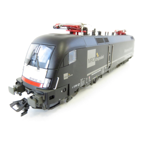
Trix E 93 Series User manual

Modell der Baureihe E 93
22870
D GB F NL

2

3
Inhaltsverzeichnis: Seite
Informationen zum Vorbild 4
Sicherheitshinweise 6
Wichtige Hinweise 6
Multiprotokollbetrieb 6
Hinweise zum Digitalbetrieb 7
Schaltbare Funktionen 9
Parameter/Register 10
Ergänzendes Zubehör 26
Betriebshinweise 27
Wartung und Instandhaltung 28
Ersatzteile 34
Table of Contents: Page
Information about the prototype 4
Safety Notes 11
Important Notes 11
Multi-Protocol Operation 11
Notes on digital operation 12
Controllable Functions 14
Parameter/Register 15
Complementary accessories 26
Information about operation 27
Service and maintenance 28
Spare Parts 34
Sommaire : Page
Informations concernant la locomotive réelle 5
Remarques importantes sur la sécurité 16
Information importante 16
Mode multiprotocole 16
Remarques relatives au fonctionnement
en mode digital 17
Fonctions commutables 19
Paramètre/Registre 20
Accessoires complémentaires 26
Remarques sur l’exploitation 27
Entretien et maintien 28
Pièces de rechange 34
Inhoudsopgave: Pagina
Informatie van het voorbeeld 5
Veiligheidsvoorschriften 21
Belangrijke aanwijzing 21
Multiprotocolbedrijf 21
Aanwijzingen voor digitale besturing 22
Schakelbare functies 24
Parameter/Register 25
Aanvullende toebehoren 26
Opmerkingen over de werking 27
Onderhoud en handhaving 28
Onderdelen 34

4
Informationen zum Vorbild
Ein stilles und arbeitsames Dasein im Schwabenland führten
lange Jahre die 18 Maschinen der Baureihe E 93. Dabei
wird leicht übersehen, dass die E 93 eine bahnbrechende
Neuentwicklung war, die speziell auf die Anforderungen der
ab 1. Juni 1933 elektrisch betriebenen württembergischen
Hauptbahn Stuttgart – Ulm ausgelegt war. Besonders die
Bewältigung der Geislinger Steige mit entsprechenden An-
hängelasten mussten ihre Konstrukteure berücksichtigen.
Die Baureihe E 93 stand meistens im Schatten ihrer größe-
ren Schwester, der E 94, die später im ganzen süddeutschen
Raum zu finden war.
Zu Unrecht, denn die E 93 war das erste „Deutsche Kroko-
dil“ und die Urahnin einer ganzen Generation von sechs-
achsigen, laufachsenlosen Elektroloks für den schweren
Güterzugdienst. Eine 50-jährige Einsatzzeit trotz ihrer eher
mäßigen Höchstgeschwindigkeit spricht für ihre robuste
Konstruktion und einfache Handhabung. Die meisten ihrer
modernen Schwestern können kaum auf ein so langes
Lokomotivleben zurückblicken.
1933 lieferte AEG die zwei ersten Exemplare als E 93 01 und
02 an das Bw Kornwestheim. Sie erfüllten voll und ganz
das vorgesehene Betriebsprogramm, das unter anderem
die Beförderung von 1.600-Tonnen-Zügen auf fünf Promille
Steigung mit einer Geschwindigkeit von 60 Kilometern pro
Stunde vorsah. Über die Geislinger Steige konnten mit
Schubloks noch 1.200 Tonnen befördert werden.
Erst 1935 folgten zwei weitere Maschinen (E 93 03 und 04).
Mit auf 70 Kilometer pro Stunde heraufgesetzter Höchstge-
schwindigkeit erschienen 1937/39 die E 93 05 bis 18, dann
trat die stärkere E 94 ihre Nachfolge an.
Information about the Prototype
The 18 machines of the E 93 class spent many years of their
quiet but industrious life in Swabia. It is easily forgotten that
the E 93 class represented a pioneering new development
specially designed to suit the demands of the Wurttemberg
main line between Stuttgart and Ulm, electrified from June
1st, 1933. Their designers had particularly to allow for nego-
tiation of the Geislingen Ramp while still hauling worthwhile
loads. The E 93 class was mostly overshadowed by its larger
sister, the E 94 class, which was later to be found all over
southern Germany.
This was unjustified, as the E 93 was the first “German
Crocodile” and the predecessor of an entire generation of
six-axle electric locos with no idler wheels for heavy freight
traffic. A 50-year service life despite their rather modest
maximum speed speaks volumes for their robust design
and their simplicity in operation. Few of their more modern
sisters will ever be able to look back over as long a service
life.
AEG delivered the first two examples, E 93 01 and 02, to the
Kornwestheim depot in 1933. They fulfilled every require-
ment of the draft operating program, which covered among
other things hauling 1,600-tonne trains up a 1 in 200 grade at
a steady speed of 60 km/h (37 mph). With pusher assistance,
even the Geislingen incline could be negotiated with 1,200
tonnes. Not until 1935 did the next two machines, E 93 03 and
04, appear. Machines E 93 05 to 93 18 followed in 1937/39,
now with a permitted top speed of 70 km/h (43-1/2 mph),
then they were succeeded by the more powerful E 94.
5
Informations concernant la locomotive réelle
Les 18 machines de la série E 93 eurent longtemps une
existence calme et travailleuse dans la Souabe. Ce faisant,
on oublie facilement que la E 93 était un nouveau dévelop-
pement révolutionnaire et avait été conçue spécialement
pour les besoins de la ligne principale wurtembourgeoise
Stuttgart – Ulm exploitée électriquement à partir du 1er
juin 1933. En particulier, les constructeurs durent tenir
compte du franchissement de la côte de Geislingen avec les
charges correspondantes. La série constructive E 93 était
le plus souvent dans l’ombre de sa grande soeur, la E 94, qui
circula plus tard dans tout le sud de l’Allemagne.
À tort, car la E 93 fut la première « Crocodile allemande »
et l’ancêtre de toute une génération de locomotives élec-
triques lourdes à six essieux, sans essieu porteur, pour le
service de marchandises lourd. Une durée de service de 50
ans malgré leur vitesse maximale plutôt moyenne parle pour
leur robustesse et leur simplicité de manipulation. La plupart
de leurs soeurs modernes ne peuvent guère faire état d’une
si longue vie active.
En 1933, AEG a livré les deux premiers exemplaires comme
E 93 01 et 02 au dépôt de Kornwestheim. Elles réalisè-
rent entièrement le programme d’exploitation prévu, qui
comprenait entre autres le transport de trains de 1.600
tonnes sur une pente de cinq pour mille à une vitesse de
60 kilomètres-heure. Avec des locomotives de manoeuvre,
on pouvait encore tout juste transporter 1.200 tonnes sur la
côte de Geislingen. Deux autres machines ne suivirent qu’en
1935 (E 93 03 et 04). Avec une vitesse maximale portée à 70
kilomètres-heure, les E 93 05 à 18 apparurent en 1937/39,
puis la E 94 plus puissante prit la succession.
Informatie van het voorbeeld
Een stil en werkzaam bestaan in het land van de Zwaben
leidden de 18 machines van de serie E 93 vele jaren lang.
Weinig bekend is dat de E 93 een baanbrekende nieuwe
ontwikkeling was. Deze was speciaal afgestemd op de eisen
van het Württembergse hoofdtracé tussen Stuttgart en Ulm,
dat vanaf 1 juni 1933 geëlektrificeerd was. In het bijzonder
met de beklimming van de Geislinger Steige en de bijbeho-
rende aanhanglasten moesten de constructeurs rekening
houden. De serie E 93 stond meestal in de schaduw van haar
grotere zus, de serie E 94, die later in heel Zuid-Duitsland te
vinden was.
Ten onrechte, want de E 93 was de eerste “Duitse Krokodil”
en de stammoeder van een generatie van zesassige, loopas-
loze elektrische locs voor de zware goederentreindienst. De
loc werd dankzij haar robuuste constructie en eenvoudige
bediening 50 jaar lang gebruikt, terwijl de maximumsnelheid
toch vrij matig was.
In 1933 leverde AEG de twee eerste exemplaren, de E 93 01
en de E 93 02, aan de spoorwegwerkplaats Kornwestheim.
Ze voldeden volledig aan de eisen, die onder andere voor-
zagen in het trekken van treinen van 1.600 ton op hellingen
van vijf promille met een snelheid van 60 kilometer per uur.
Over de Geislinger Steige kon met duwlocs 1.200 ton worden
vervoerd. In 1935 volgden twee andere machines (E 93 03 en
E 93 04). Met een verhoogde topsnelheid van 70 kilometer
per uur verschenen van 1937 tot 1939 de locs E 93 05 tot E 93
18. Daarna kwam de sterkere opvolger E 94.

6
Sicherheitshinweise
• DieLokdarfnurmiteinemdafürbestimmtenBetriebssys-
tem eingesetzt werden.
• Analogmax.15Volt=,digitalmax.22Volt~.
• DieLokdarfnurauseinerLeistungsquelleversorgtwer-
den.
• BeachtenSieunbedingtdieSicherheitshinweiseinder
Bedienungsanleitung zu Ihrem Betriebssystem.
•FürdenkonventionellenBetriebderLokmussdasAn-
schlussgleis entstört werden. Dazu ist das Entstörset
611 655 zu verwenden. Für Digitalbetrieb ist das Entstörset
nicht geeignet.
• ACHTUNG! Funktionsbedingte scharfe Kanten und Spitzen.
•SetzenSiedasModellkeinerdirektenSonneneinstrah-
lung, starken Temperaturschwankungen oder hoher
Luftfeuchtigkeit aus.
Wichtige Hinweise
• BedingtdurchdieLackierungkönnensichanfangsanden
Dach-Stromabnehmern Kontaktprobleme ergeben. Nach
kurzem Einfahren sind die Kontaktprobleme nicht mehr
vorhanden.
•DieBedienungsanleitungunddieVerpackungsindBe-
standteile des Produktes und müssen deshalb aufbewahrt
sowie bei Weitergabe des Produktes mitgegeben werden.
•FürReparaturenoderErsatzteilewendenSiesichbittean
Ihren Trix-Fachhändler.
•GewährleistungundGarantiegemäßderbeiliegenden
Garantieurkunde.
•Entsorgung:www.maerklin.com/en/imprint.html
•DervolleFunktionsumfangistnurunterTrixSystems,DCC
und unter mfx verfügbar.
• Eingebaute,fahrtrichtungsabhängigeStirnbeleuchtung.
Im Digitalbetrieb schaltbar.
•BefahrbarerMindestradius360mm.
Multiprotokollbetrieb
Analogbetrieb
Der Decoder kann auch auf analogen Anlagen oder Gleis-
abschnitten betrieben werden. Der Decoder erkennt die
analoge Gleichspannung (DC) automatisch und passt sich
der analogen Gleisspannung an. Es sind alle Funktionen,
die unter mfx oder DCC für den Analogbetrieb eingestellt
wurden aktiv (siehe Digitalbetrieb).
Digitalbetrieb
Der Decoder ist ein Multiprotokolldecoder. Der Decoder
kannunterfolgendenDigital-Protokolleneingesetztwerden:
mfx oder DCC.
Das Digital-Protokoll mit den meisten Möglichkeiten ist das
höchstwertige Digital-Protokoll. Die Reihenfolge der Digital-
ProtokolleistinderWertungfallend:
Priorität1:mfx
Priorität2:DCC
Priorität3:DC
Hinweis: Digital-Protokolle können sich gegenseitig beein-
flussen. Für einen störungsfreien Betrieb empfehlen wir,
nicht benötigte Digital-Protokolle mit CV 50 zu deaktivieren.
Deaktivieren Sie, sofern dies Ihre Zentrale unterstützt, auch
dort die nicht benötigten Digital-Protokolle.

7
Werden zwei oder mehrere Digital-Protokolle am Gleis
erkannt, übernimmt der Decoder automatisch das höchst-
wertige Digital-Protokoll, z.B. mfx/DCC, somit wird das
mfx-Digital-Protokoll vom Decoder übernommen.
Hinweis: Beachten Sie, dass nicht alle Funktionen in allen
Digital-Protokollen möglich sind. Unter mfx und DCC können
einige Einstellungen von Funktionen, welche im Analog-
Betrieb wirksam sein sollen, vorgenommen werden.
Hinweise zum Digitalbetrieb
• DiegenaueVorgehensweisezumEinstellenderdiversen
Parameter entnehmen Sie bitte der Bedienungsanleitung
Ihrer Mehrzug-Zentrale.
•DieabWerkeingestelltenWertesindfürmfxgewählt,so
dass ein bestmöglichstes Fahrverhalten gewährleistet ist.
Für andere Betriebssysteme müssen gegebenenfalls
Anpassungen getätigt werden.
• DerBetriebmitgegenpoligerGleichspannungim
Bremsabschnitt ist mit der werkseitigen Einstellung nicht
möglich. Ist diese Eigenschaft gewünscht, so muss auf
den konventionellen Gleichstrombetrieb verzichtet werden
(CV29/Bit2=0).
mfx-Protokoll
Adressierung
• KeineAdresseerforderlich,jederDecodererhälteine
einmalige und eindeutige Kennung (UID).
• DerDecodermeldetsichaneinerCentralStationoder
Mobile Station mit seiner UID automatisch an.
• NameabWerk:E 93 07 DB
Programmierung
• DieEigenschaftenkönnenüberdiegrascheOberäche
der Central Station bzw. teilweise auch mit der Mobile
Station programmiert werden.
• EskönnenalleCongurationVariablen(CV)mehrfach
gelesen und programmiert werden.
• DieProgrammierungkannentwederaufdemHaupt-oder
dem Programmiergleis erfolgen.
• DieDefaulteinstellungen(Werkseinstellungen)können
wieder hergestellt werden.
• Funktionsmapping:FunktionenkönnenmitHilfeder
Central Station 60213/60214/60215 beliebigen Funktionsta-
sten zugeordnet werden (siehe Hilfe in der Central Station).
DCC-Protokoll
Adressierung
• MöglicheAdressen:Kurze,langeundTraktionsadresse
• Adressbereich:
1 – 127 (kurze Adresse, Traktionsadresse)
1 – 10239 (lange Adresse)
• JedeAdresseistmanuellprogrammierbar.
•KurzeoderlangeAdressewirdüberdieCVsausgewählt.
• EineangewandteTraktionsadressedeaktiviertdie
Standard-Adresse.
Programmierung
• DieEigenschaftenkönnenüberdieCongurationsVari-
ablen (CV) mehrfach geändert werden.
• DieCV-NummerunddieCV-Wertewerdendirekteingege-
ben.

8
• DieCVskönnenmehrfachgelesenundprogrammiert
werden (Programmierung auf dem Programmiergleis).
• DieCVskönnenbeliebigprogrammiertwerden.PoM(Pro-
grammierung auf dem Hauptgleis PoM) ist nur bei den in
der CV-Tabelle gekennzeichneten CV möglich. PoM muss
von Ihrer Zentrale unterstützt werden (siehe Bedienungs-
anleitung ihres Gerätes).
• DieDefaulteinstellungen(Werkseinstellungen)können
wieder hergestellt werden.
• 14bzw.28/126Fahrstufeneinstellbar.
• AlleFunktionenkönnenentsprechenddemFunktionsmap-
ping geschaltet werden.
• WeitereInformation,sieheCV-TabelleDCC-Protokoll.
Es wird empfohlen, die Programmierungen grundsätzlich auf
dem Programmiergleis vorzunehmen.
Logische Funktionen
Anfahr-/Bremsverzögerung
• DieBeschleunigungs-undBremszeitkönnengetrenntvon
einander eingestellt werden.
• DielogischeFunktionsabschaltungABVkannüberdas
Funktionsmapping auf jede beliebige Funktionstaste gelegt
werden.

9
Schaltbare Funktionen
STOP mobile station
15
f0 f8 f0f8
Spitzensignal an Funktion f0 Funktion f0
Führerstandsbeleuchtung — Funktion 1 Funktion f1 Funktion f1
Geräusch:Betriebsgeräusch — Funktion 2 Funktion f2 Funktion f2
Geräusch:Lokpfeife — Funktion 3 Funktion f3 Funktion f3
ABV, aus — Funktion 4 Funktion f4 Funktion f4
Geräusch:Bremsenquietschenaus — Funktion 5 Funktion f5 Funktion f5
Spitzensignal Führerstand 2 aus — + 1 f0 + f6 f0 + f6
Geräusch:Rangierpff — Funktion 7 Funktion f7 Funktion f7
Spitzensignal Führerstand 1 aus — + 8 f0 + f8 f0 + f8
Geräusch:Sanden — — Funktion f9 Funktion f9
Geräusch:Lüfter — — Funktion f10 Funktion f10
Geräusch:Kuppeln — — Funktion f11 Funktion f11
Geräusch:Bahnhofsansage„Zugfährtdurch“ — — Funktion f12 Funktion f12
Rangierlicht doppel A — + 1 + 8 f0 + f6 + f8 f0 + f6 + f8
F0 F4

10
CV Bedeutung Wert DCC ab Werk
1 Adresse 1 - 127 3
2 PoM Minimalgeschwindigkeit 0 - 255 8
3 PoM Anfahrverzögerung 0 - 255 10
4 PoM Bremsverzögerung 0 - 255 15
5 PoM Maximalgeschwindigkeit 0 - 255 220
8 Werkreset/Herstellerkennung 8 131
13 PoM Funktionen F1 - F8 im Analogbetrieb 0 - 255 0
14 PoM Funktionen F9 - F15 und Licht im Analogbetrieb 0 - 255 1
17 Erweiterte Adresse (oberer Teil) CV29,Bit5=1 192
18 Erweiterte Adresse (unterer Teil) CV29,Bit5=1 128
19 Traktionsadresse 0 - 255 0
21 PoM Funktionen F1 - F8 bei Traktion 0 - 255 0
22 PoM Funktionen F9 - F15 und Licht bei Traktion 0 - 255 0
29 PoM
Bit0:UmpolungFahrtrichtung
Bit1:AnzahlFahrstufen14oder28/128*
Bit2:DCCBetriebmitBremsstrecke(keinAnalogbetriebmöglich)
Bit5:kurze/langeAdresse
0 / 1
0 / 2
0 / 4
0 / 32
0, 1, 2, 3, 4, 5, 6,
7, 32, 34, 35, 36,
37, 38, 39 6
63 PoM Lautstärke 0 - 255 255
* FahrstufenamLokdecoderundamSteuergerätmüssenübereinstimmen,essindsonstFehlfunktionenmöglich.

11
•ThefullrangeoffunctionsisonlyavailableunderTrix
Systems and under DCC and mfx.
• Built-inheadlightsthatchangeoverwiththedirectionof
travel. They can be turned on and off in digital operation.
•Minimumradiusforoperationis360mm/14-3/16“.
Multi-Protocol Operation
Analog Operation
This decoder can also be operated on analog layouts or ar-
eas of track that are analog. The decoder recognizes alter-
nating current (DC) and automatically adapts to the analog
track voltage. All functions that were set under mfx or DCC
for analog operation are active (see Digital Operation).
Digital Operation
The decoders are multi-protocol decoders. These decoders
canbeusedunderthefollowingdigitalprotocols:mfxorDCC.
The digital protocol with the most possibilities is the highest
order digital protocol. The sequence of digital protocols in
descendingorderis:
Priority1:mfx
Priority2:DCC
Priority3:DC
Note: Digital protocols can influence each other. For trouble-
free operation, we recommend deactivating those digital
protocols not needed by using CV 50. Deactivate unneeded
digital protocols at this CV if your controller supports this
function.
If two or more digital protocols are recognized in the track,
Safety Notes
• Thislocomotiveisonlytobeusedwiththeoperating
system it is designed for.
• Analogmax.15voltsDC,digitalmax.22voltsAC.
• Thislocomotivemustneverbesuppliedwithpowerfrom
more than one power pack.
• Pleasemakenoteofthesafetynotesintheinstructionsfor
your operating system.
•Thefeedertrackmustbeequippedtopreventinterference
with radio and television reception, when the locomotive
is to be run in conventional operation. The 611 655 inter-
ference suppression set is to be used for this purpose.
The interference suppression set is not suitable for digital
operation.
• WARNING! Sharp edges and points required for operation.
•Donotexposethemodeltodirectsunlight,extreme
changes in temperature, or high humidity.
Important Notes
• Thepaintonthepantographsmayatrstcausecontact
problems on these units.The contact problems will go
away after the model has run for a short time.
•Theoperatinginstructionsandthepackagingareacom-
ponent part of the product and must therefore be kept as
well as transferred along with the product to others.
•PleaseseeyourauthorizedTrixdealerforrepairsorspare
parts.
•Thewarrantycardincludedwiththisproductspeciesthe
warranty conditions.
•Disposing:www.maerklin.com/en/imprint.html

12
the decoder automatically takes on the highest order digital
protocol,example:mfx/DCC;thedecodertakesonthemfx
digital protocol (see previous table).
Note: Please note that not all functions are possible in all
digital protocols. Several settings for functions, which are
supposed to be active in analog operation, can be done
under mfx and DCC.
Notes on digital operation
•Theoperatinginstructionsforyourcentralunitwillgive
you exact procedures for setting the different parameters.
•Thevaluessetatthefactoryhavebeenselectedformfxin
order to guarantee the best possible running characteri-
stics.
Adjustments may have to be made for other operating
systems.
• Thesettingdoneatthefactorydoesnotpermitoperation
with opposite polarity DC power in the braking block. If
you want this characteristic, you must do without conven-
tionalDCpoweroperation(CV29/Bit2=0).
mfx Protocol
Addresses
•Noaddressisrequired;eachdecoderisgivenaone-time,
unique identifier (UID).
•ThedecoderautomaticallyregistersitselfonaCentral
Station or a Mobile Station with its UID.
• Namesetatthefactory:E 93 07 DB
Programming
•Thecharacteristicscanbeprogrammedusingthegraphic
screen on the Central Station or also partially with the
Mobile Station.
•AlloftheCongurationVariables(CV)canbereadand
programmed repeatedly.
•Theprogrammingcanbedoneeitheronthemaintrackor
the programming track.
•Thedefaultsettings(factorysettings)canbeproduced
repeatedly.
•Functionmapping:Functionscanbeassignedtoanyof
the function buttons with the help of the 60213/60214/60215
Central Station (See help section in the Central Station).
DCC Protocol
Addresses
• Possibleaddresses:short,long,andm.u.address
• Addressrange:
1 – 127 (short address, m.u. address)
1 – 10239 (long address)
•Everyaddresscanbeprogrammedmanually.
•AshortoralongaddressisselectedusingtheCVs.
•Amultipleunitaddressthatisbeinguseddeactivatesthe
standard address.
Programming
•Thecharacteristicscanbechangedrepeatedlyusingthe
Configuration Variables (CV).
•TheCVnumbersandtheCVvaluesareentereddirectly.

13
•TheCVscanbereadandprogrammedrepeatedly.(Pro-
gramming is done on the programming track.)
•TheCVscanbeprogrammed,asyoudesire.PoM
(Programming on the layout track) is only possible with
those CVs marked in the CV table. PoM must be supported
by your central controller (see the instructions for your
controller).
•Thedefaultsettings(factorysettings)canbeproduced
repeatedly.
•14/28or126speedlevelscanbeset.
•Allofthefunctionscanbecontrolledaccordingtothe
function mapping (see CV description).
•SeetheCVdescriptionfortheDCCprotocolforadditional
information.
We recommend that in general programming should be
done on the programming track.
Logic Functions
Acceleration / Braking Delay
• Theaccelerationandbrakingtimescanbesetseparately
from each other.
• ThelogicalfunctionshutoffforABV(Acceleration/
Braking Delay) can be assigned to any function button by
means of function mapping.

14
Controllable Functions
STOP mobile station
15
F0 F4 f0 f8 f0f8
Headlights on Function f0 Function f0
Engineer‘s cab lighting — Function 1 Function f1 Function f1
Soundeffect:Operatingsounds — Function 2 Function f2 Function f2
Soundeffect:Locomotivewhistle — Function 3 Function f3 Function f3
ABV, off — Function 4 Function f4 Function f4
Soundeffect:Squealingbrakesoff — Function 5 Function f5 Function f5
Headlights Engineer‘s Cab 2 off — + 1 f0 + f6 f0 + f6
Soundeffect:Switchingwhistle — Function 7 Function f7 Function f7
Headlights Engineer‘s Cab 1 off — + 8 f0 + f8 f0 + f8
Soundeffect:sanding — — Function f9 Function f9
Soundeffect:Blower — — Function f10 Function f10
Soundeffect:Soundsofcouplers — — Function f11 Function f11
Soundeffect:Stationannouncements„Zug
fährt durch“ — — Function f12 Function f12
Double A switching light — + 1 + 8 f0 + f6 + f8 f0 + f6 + f8

15
* Thespeedlevelsonthelocomotivedecoderandonthecontrollermustagreewitheachother;otherwise,
you may have malfunctions.
CV Discription DCC Value Factory-Set
1 Address 1 - 127 3
2 PoM Minimum Speed 0 - 255 8
3 PoM Acceleration delay 0 - 255 10
4 PoM Braking delay 0 - 255 15
5 PoM Maximum speed 0 - 255 220
8 Factory Reset / Manufacturer Recognition 8 131
13 PoM Functions F1 - F8 in analog operation 0 - 255 0
14 PoM Functions F9 - F15 and lights in analog operation 0 - 255 1
17 Extended address (upper part) CV29,Bit5=1 192
18 Extended address (lower part) CV29,Bit5=1 128
19 Multiple Unit Address 0 - 255 0
21 PoM Functions F1 - F8 on Multiple Unit 0 - 255 0
22 PoM Functions F9 - F15 and lights on Multiple Unit 0 - 255 0
29 PoM
Bit0:Reversingdirectionoftravel
Bit1:Numberofspeedlevels14or28/128*
Bit2:DCCoperationwithabrakingarea(noanalogoperation
possible)
Bit5:short/longaddress
0 / 1
0 / 2
0 / 4
0 / 32
0, 1, 2, 3, 4, 5, 6,
7, 32, 34, 35, 36,
37, 38, 39 6
63 PoM Volume 0 - 255 255

16
Remarques importantes sur la sécurité
• Lalocomotivenepeutêtreutiliséequ‘aveclesystème
d‘exploitation indiqué.
• Analogiquemax.15Volt=,digitalmax.22Volt~.
• Lalocomotivenepeutpasêtrealimentéeélectriquement
par plus d‘une source de courant à la fois.
• Ilestimpératifdetenircomptedesremarquessurla
sécurité décrites dans le mode d‘emploi de votre système
d‘exploitation.
•
Pour l’exploitation de la locomotive en mode conventi-
onnel, la voie de raccordement doit être déparasitée. A cet
effet, utiliser le set de déparasitage réf. 611 655. Le set de
déparasitage ne convient pas pour l’exploitation en mode
numérique.
•
ATTENTION! Pointes et bords coupants lors du fonctionne-
ment du produit.
•Nepasexposerlemodèleàunensoleillementdirect,àde
fortes variations de température ou à un taux d‘humidité
important.
Information importante
• Audébut,levernispeutêtreàl’originedeproblèmes
de contact au niveau des pantographes. Ces problèmes
disparaissent après un court rodage.
•Lanoticed‘utilisationetl’emballagefontpartieintégrante
duproduit;ilsdoiventdoncêtreconservéset,lecas
échéant, transmis avec le produit.
•Pourtouteréparationouremplacementdepièces,
adressez vous à votre détaillant-spécialiste Trix.
•Garantielégaleetgarantiecontractuelleconformément
au certificat de garantie ci-joint.
•Elimination:www.maerklin.com/en/imprint.html
•L’intégralitédesfonctionsestdisponibleuniquementen
exploitation Trix Systems, DCC et mfx.
• Feuxdesignalisations‘inversantselonlesensdemarche;
feux commutables en exploitation digital.
•Rayonminimald’inscriptionencourbe360mm.
•Installationultérieured’ungénérateurdefuméepossible-
également pour exploitation analogique.
Mode multiprotocole
Mode analogique
On peut aussi faire fonctionner le décodeur sur des instal-
lations ou des sections de voie analogiques. Le décodeur
identifie automatiquement la tension de voie analogique (CC).
Toutes les fonctions qui ont été paramétrée pour le mode
analogique sous mfx ou sous DCC sont actives (voir mode
numérique).
Mode numérique
Les décodeur sont des décodeur multiprotocole. Le
décodeur peut être utilisé avec les protocoles numériques
suivants:mfx,DCC
Le protocole numérique offrant les possibilités les plus
nombreuses est le protocole numérique à bit de poids
fort. La hiérarchisation des protocoles numériques est
descendante:
Priorité1:mfx
Priorité2:DCC
Priorité3:DC

17
Indication : des protocoles numériques peuvent s’influencer
réciproquement. Pour une exploitation sans perturbations,
nous recommandons de désactiver avec CV 50 des proto-
coles numériques non nécessaires.
Dans la mesure où votre centrale les supporte, désactivez y
aussi les protocoles numériques non nécessaires.
Lorsque deux ou plusieurs protocoles numériques sont
identifiés au niveau de la voie, le décodeur reprend automa-
tiquement le protocole numérique à bit de poids fort, p. ex.
mfx/DCC. Le protocole numérique mfx est donc repris par le
décodeur (voir tableau antérieur).
Indication : remarquez que toutes les fonctions ne peuvent
pas être actionnées dans tous les protocoles numériques.
Sous mfx et sous DCC, il est possible de procéder à
quelques paramétrages de fonctions devant être actives
dans le cadre de l’exploitation analogique.
Remarques relatives au fonctionnement en mode digital
•Encequiconcernelaprocédurederéglagedesdiverspa-
ramètres, veuillez vous référer au mode d‘emploi de votre
centrale de commande multitrain.
•Lesvaleursparamétréesd’usinesontchoisiespourmfxde
manière à garantir le meilleur comportement de roulement
possible.
Pour d’autres systèmes d’exploitation, ces valeurs devront
éventuellement être adaptées.
• L’exploitationaveccourantcontinudepolaritéinverse
dans les sections de freinage n’est pas possible avec le
réglage d’usine. Si cette propriété est désirée, il faut alors
renoncer à l’exploitation conventionnelle en courant conti-
nu(CV29/Bit2=0).
Protocole mfx
Adressage
• Aucuneadressen’estnécessaire,ledécodeurreçoit
toutefois une identification unique et non équivoque (UID).
• AvecsonUID,ledécodeurindiqueautomatiquement
à une station centrale ou à une station mobile qu’il est
connecté.
• Nomencodeeenusine:E 93 07 DB
Programmation
• Lescaractéristiquespeuventêtreprogramméespar
l’intermédiaire de la couche graphique de la station cen-
trale, voire en partie aussi au moyen de la station mobile.
• Touteslescongurationsvariables(CV)peuventêtrelues
et programmées de façon réitérée.
• Laprogrammationpeutêtreréaliséesoitsurlavoieprinci-
pale, soit sur la voie de programmation.
• Lesparamétragespardéfaut(paramétragesusine)
peuvent être rétablis.
• Mappagedesfonctions:lesfonctionspeuventêtreaffec-
tées à de quelconques touches de fonction au moyen de
la station centrale 60213/60214/60215 (voir Aide au niveau
de la station centrale).
Protocole DCC
Adressage
• Adressepossibles:Courtes,longuesetadressesdetraction
• Catégoried’adresse:
1 à 127 (adresses courtes, adresses de traction)
1 à 10239 (adresses longues)

18
• Chaqueadresseestprogrammablemanuellement.
•L’adressebrèveoulongueestchoisieparl’intermédiaire
des CVs.
• Uneadressedetractionutiliséedésactivel’adresse
standard.
Programmation
• Lescaractéristiquespeuventêtremodiéesdefaçonréité-
rée par l’intermédiaire des variables de configuration (CVs).
• Touteslescongurationsvariables(CV)peuventêtrelues
et programmées de façon réitérée.
• Laprogrammationpeutêtreréaliséesoitsurlavoieprinci-
pale, soit sur la voie de programmation.
• LesCVpeuventêtreprogramméeslibrement.LaPoM
(programmation sur la voie principale) est possible
uniquement pour les CV signalées dans le tableau des CV.
La PoM doit être prise en charge par votre centrale (voir la
notice d’utilisation de votre appareil).
• Lesparamétragespardéfaut(paramétragesusine)
peuvent être rétablis.
• 14/28,voire126cransdemarchesontparamétrables.
• Touteslesfonctionspeuventêtrecommutéesenfonction
du mappage des fonctions (voir le descriptif des CVs).
• Pourtouteinformationcomplémentaire,voirletableaudes
CVs, protocole DCC.
Il est recommandé, de réaliser la programmation, fonda-
mentalement, sur la voie de programmation.
Fonctions logiques
Temporisation d’accélération et de freinage (TAF)
• Lestempsd’accélérationetdefreinagepeuventêtre
définis indépendamment l’un de l’autre.
• LadésactivationdelafonctionlogiqueTAFpeutêtre
affectée à n’importe quelle touche de fonction via le
mappage de fonctions.

19
Fonctions commutables
STOP mobile station
15
F0 F4 f0 f8 f0f8
Fanal éclairage Activé Fonction f0 Fonction f0
Eclairage de la cabine de conduite — Fonction 1 Fonction f1 Fonction f1
Bruitage:Bruitd’exploitation — Fonction 2 Fonction f2 Fonction f2
Bruitage:Sifetlocomotive — Fonction 3 Fonction f3 Fonction f3
ABV, désactivé — Fonction 4 Fonction f4 Fonction f4
Bruitage:Grincementdefreinsdésactivé — Fonction 5 Fonction f5 Fonction f5
Fanal cabine de conduite 2 éteint — + 1 f0 + f6 f0 + f6
Bruitage:Sifetpourmanœuvre — Fonction 7 Fonction f7 Fonction f7
Fanal cabine de conduite 1 éteint — + 8 f0 + f8 f0 + f8
Bruitage:Sablage — — Fonction f9 Fonction f9
Bruitage:Ventilateur — — Fonction f10 Fonction f10
Bruitage:Bruitd’attelage — — Fonction f11 Fonction f11
Bruitage:Annonceengare„Zugfährt
durch“ — — Fonction f12 Fonction f12
FeudemanœuvredoubleA —+ 1 + 8 f0 + f6 + f8 f0 + f6 + f8

20
CV Affectation DCC Valeur Parm. Usine
1 Adresse 1 - 127 3
2 PoM Vitesse minimale 0 - 255 8
3 PoM Temporisation d‘accélération 0 - 255 10
4 PoM Temporisation de freinage 0 - 255 15
5 PoM Vitesse maximale 0 - 255 220
8 Réinitialisation d’usine/identification du fabricant 8 131
13 PoM Fonctions F1 - F8 en mode analogique 0 - 255 0
14 PoM Fonctions F9 - F15 et éclairage en mode analogique 0 - 255 1
17 Adresse étendue (partie supérieure) CV29,Bit5=1 192
18 Adresse étendue (partie inférieure) CV29,Bit5=1 128
19 Adresse traction 0 - 255 0
21 PoM Fonctions F1 - F8 pour traction 0 - 255 0
22 PoM Fonctions F9 - F15 et éclairage traction 0 - 255 0
29 PoM
Bit0:Inversiondusensdemarche
Bit1:Nombredecransdemarche14ou28/128*
Bit2:ExploitationDCCavecsectiondefreinage(exploitation
analogique impossible)
Bit5:Adressecourte/longue
0 / 1
0 / 2
0 / 4
0 / 32
0, 1, 2, 3, 4, 5, 6,
7, 32, 34, 35, 36,
37, 38, 39 6
63 PoM Volume 0 - 255 255
* Pourévitertoutdysfonctionnement,lescransdemarchesurledécodeurdelocodoiventimpérativement
coïncider avec ceux de l’appareil de commande.
This manual suits for next models
1
Table of contents
Languages:
Other Trix Toy manuals

Trix
Trix h0 series User manual

Trix
Trix BR 03 Altbau User manual

Trix
Trix 22658 User manual

Trix
Trix BR 24 User manual

Trix
Trix BR 146.2 TRAXX User manual

Trix
Trix 5600 Series User manual

Trix
Trix RAe 4/8 User manual

Trix
Trix Re 4/4II User manual

Trix
Trix Minitrix 66148 User manual

Trix
Trix BR 144 User manual
Popular Toy manuals by other brands

Flycatcher
Flycatcher smART sketcher Projector user manual

Rail King
Rail King F-3 Passenger Set operating instructions

iKarus
iKarus SHOCK FLYER F3A Building instructions

Hasbro
Hasbro Transformers 85772 Asst. installation guide

Velleman
Velleman KNS8 user manual

Reely
Reely Beginner Falcon V2 RtF operating instructions