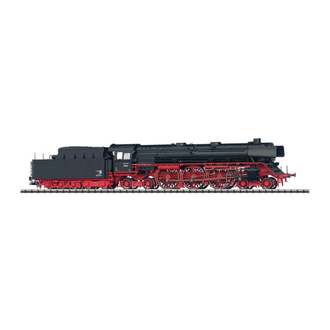
Trix 5600 Series User manual

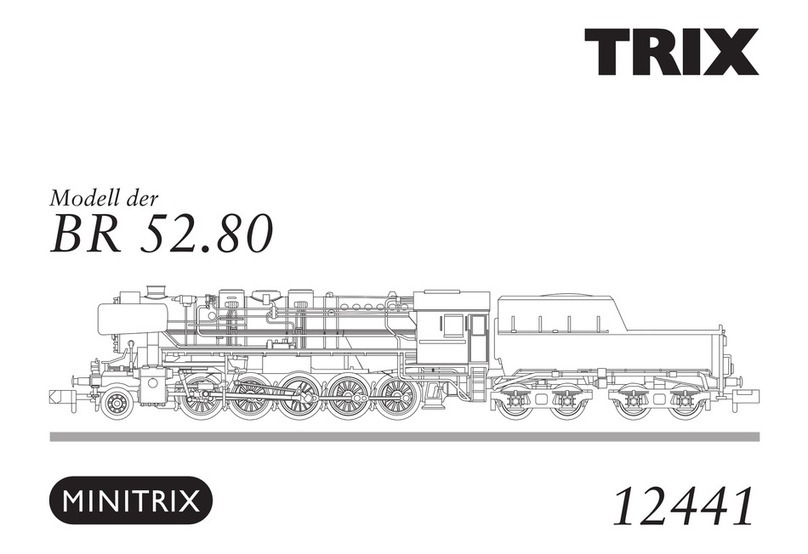
Modell der Dampflok Serie 5600
22253

2
Inhaltsverzeichnis: Seite
Informationen zum Vorbild 4
Betriebshinweise 6
Sicherheitshinweise 7
Wichtige Hinweise 7
Funktionen 7
Schaltbare Funktionen 8
CVs und Parameter 9
Ergänzendes Zubehör 31
Wartung und Instandhaltung 33
Ersatzteile 37
Table of Contents: Page
Information about the prototype 4
Information about operation 6
Safety Notes 10
Important Notes 10
Functions 10
Controllable Functions 11
CVs and Parameters 12
Complementary accessories 31
Service and maintenance 33
Spare Parts 37
Sommaire : Page
Informations concernant la locomotive réelle 5
Remarques sur l’exploitation 6
Remarques importantes sur la sécurité 13
Information importante 13
Fonctionnement 13
Fonctions commutables 14
CVs et paramètres 15
Accessoires complémentaires 31
Entretien et maintien 33
Pièces de rechange 37
Inhoudsopgave: Pagina
Informatie van het voorbeeld 5
Opmerkingen over de werking 6
Veiligheidsvoorschriften 16
Belangrijke aanwijzing 16
Functies 16
Schakelbare functies 17
CV’s en parameter 18
Aanvullende toebehoren 31
Onderhoud en handhaving 33
Onderdelen 37

3
Indice de contenido: Página
Instrucciones de uso 6
Aviso de seguridad 19
Notas importantes 19
Funciones 19
Funciones posibles 20
CVs y parámetros 21
Accesorios complementarios 31
El mantenimiento 33
Recambios 37
Indice del contenuto: Pagina
Avvertenze per il funzionamento 6
Avvertenze per la sicurezza 22
Avvertenze importanti 22
Funzioni 22
Funzioni commutabili 23
CV e parametri 24
Accessori complementari 31
Manutenzione ed assistere 33
Pezzi di ricambio 37
Innehållsförteckning: Sida
Driftanvisningar 6
Säkerhetsanvisningar 25
Viktig information 25
Funktioner 25
Kopplingsbara funktioner 26
CV och parametrar 27
Ytterligare tillbehör 31
Underhåll och reparation 33
Reservdelar 37
Indholdsfortegnelse: Side
Brugsanvisninger 6
Vink om sikkerhed 28
Vigtige bemærkninger 28
Funktioner 28
Styrbare funktioner 29
CV‘er og parametre 30
Ekstra tilbehør 31
Service og reparation 33
Reservedele 37

4
Informationen zum Vorbild
Für die umfangreichen Transportaufgaben, die die Deutsche
Reichsbahn während des Zweiten Weltkrieges erledigen muss-
te, wurden leistungsfähige Lokomotiven benötigt, die auch auf
Strecken mit geringer Achslast eingesetzt werden konnten.
Um in möglichst kurzer Zeit eine große Zahl solcher Lokomoti-
ven herstellen zu können, wurde angestrebt, Konstruktion und
Fertigung gegenüber den bisherigen Bauarten erheblich zu
vereinfachen.
Aus der Lokomotivbaureihe 50 wurde daher durch konsequente
„Entfeinerung“ die Baureihe 52 entwickelt. Diese Baureihe wur-
de dann in den Jahren 1942 bis 1945 mit über 6.000 Exemplaren
in deutschen und ausländischen Lokomotivfabriken gebaut. Sie
war in der Lage, Güterzüge mit einem Gesamtgewicht von 635
Tonnen in der Ebene mit einer Geschwindigkeit von 80 km/h zu
befördern, auf Steigungen von 10‰ konnte sie noch 415 Tonnen
mit 50 km/h ziehen.
Wegen der großen Stückzahl waren diese Lokomotiven auch
nach dem Krieg nicht nur in beiden Teilen Deutschlands,
sondern auch in vielen anderen europäischen Ländern häufig
zu sehen.
Information about the Prototype
Powerful locomotives were required for the extensive transpor-
tation tasks that the German State Railroad had to take care of
during World War II. These locomotives had to have a low axle
load for routes with substandard track.
In order to be able to produce a large number of such locomo-
tives in the shortest possible time, efforts were made to simplify
the design and manufacture in comparison to the predecessor
classes.
The class 52 was therefore developed from the class 50 by
means of consistent “reverse refinement”. Over 6,000 of this
class were built in the years 1942 to 1945 by German and foreign
locomotives builders. They were capable of pulling freight trains
with a total weight of 635 tons on level track at a speed of 80
km/h (50 m.p.h.), on 10‰ grades they could still pull 415 tons at a
speed of 50 km/h (approx. 31 m.p.h.).
Because of the large number of these locomotives, after the war
they were often to be seen not only in both parts of Germany, but
also in many other European countries.

5
Informations concernant la locomotive réelle
Des locomotives performantes étaient nécessaires pour assu-
mer les transports volumineux que devait, prendre en charge les
Chemins de fer de la Deutsche Reichsbahn pendant la Seconde
Guerre Mondiale. Elles devaient pouvoir être utilisées sur des
lignes avec faible charge axiale.
Afin de pouvoir fabriquer un grand nombre de locomotives de ce
genre en peu de temps, on chercha à simplifier la construction
et la fabrication par rapport aux types précédents.
C’est ainsi que l’on développa la série 52, en simplifiant sans
cesse la série de locomotives 50. Cette série fut ensuite
fabriqués en plus de 6 000 exemplaires, dans des usines de
locomotives allemandes et étrangères, entre 1942 et 1945. Elle
était en mesure de transporter des trains de marchandises d’un
poids total de 635 tonnes en plaire avec une vitesse de 80 km/h.
Dans des montées de 10‰, elle parvenait encore à tracter 415
tonnes, à 50 km/h.
En raison du grand nombre d’unités, ces locomotives étaient
courantes après la guerre, non seulement dans les deux parties
de l’Allemagne, mais aussi dans ce nombreux autres pays
européens.
Informatie van het voorbeeld
Voor de uitgebreide transporttaken die de Deutsche Reichsbahn
tijdens de Tweede Wereldoorlog moet uitvoeren, waren sterke
locomotieven nodig, die ook op trajecten waar geringe asdruk
toegelaten was, ingezet konden worden.
Om in zo kort mogelijke tijd een groot aantal van zulke loco-
motieven te kunnen produceren, werd er naar gestreefd de
constructie en de fabricage ten opzichte van de gebruikelijke
typen aanzienlijk te vereenvoudigen.
Uit de locomotiefserie 50 werd daarom door consequente „ver-
fijnering” de serie 52 ontwikkeld. Deze serie werd vervolgens
in de jaren 1942 tot en met 1945 in meer dan 6000 exemplaren
in Duitse en buitenlandse locomotieffabrieken gebouwd. De lok
was in staat goederentreinen met een totaal gewicht van 635 ton
op vlak terrein met een snelheid van 80 km/h te vervoeren, op
hellingen van 10‰ konden ze nog 415 ton met 50 km/h trekken.
Door hun grote aantal waren deze locomotieven ook na de oor-
log niet alleen in de twee Duitslanden, maar ook in vele andere
Europese landen vaak te vinden.

6
Kolbenstangenschutzrohr einsetzen
How to install the cylinder rot protector
Insérer le tube de protection de la lige de piston
Beschermbuis cilinderstang plaatsen
Colocar el tubo protector de la biela
Installazione del tubetto di protezione per l’asta dello stantuffo
Kolvstångsskyddsröret monteras
Cylinderstang-beskyttelsesør indsættes
Radius > 500 mm

7
Sicherheitshinweise
• DieLokdarfnurmiteinemdafürbestimmtenBetriebssystem
eingesetzt werden.
• Analogmax.15Volt=,digitalmax.22Volt~.
• DieLokdarfnurauseinerLeistungsquelleversorgtwerden.
• BeachtenSieunbedingtdieSicherheitshinweiseinder
Bedienungsanleitung zu Ihrem Betriebssystem.
• FürdenkonventionellenBetriebderLokmussdasAnschluss-
gleis entstört werden. Dazu ist das Entstörset 611 655 zu ver-
wenden. Für Digitalbetrieb ist das Entstörset nicht geeignet.
• ACHTUNG! Funktionsbedingte scharfe Kanten und Spitzen.
• SetzenSiedasModellkeinerdirektenSonneneinstrahlung,
starken Temperaturschwankungen oder hoher Luftfeuchtig-
keit aus.
Wichtige Hinweise
• DieBedienungsanleitungunddieVerpackungsindBestand-
teil des Produktes und müssen deshalb aufbewahrt sowie bei
Weitergabe des Produktes mitgegeben werden.
• FürReparaturenoderErsatzteilewendenSiesichbittean
Ihren Trix-Fachhändler.
• GewährleistungundGarantiegemäßderbeiliegendenGaran-
tieurkunde.
• http://www.maerklin.com/en/imprint.html
Funktionen
• EingebauteElektronikzumwahlweisenBetriebmitkonventio-
nellem Gleichstrom-Fahrgerät, Trix Systems oder Digitalsyste-
men nach NMRA-Norm.
• AutomatischeSystemerkennungzwischenDigital-und
Analog-Betrieb.
• DervolleFunktionsumfangistnurunterTrixSystemsund
unter DCC verfügbar.
• Eingebaute,fahrtrichtungsabhängigeStirnbeleuchtung.
Im Digitalbetrieb schaltbar.
• BefahrbarerMindestradius360mm.
Hinweise zum Digitalbetrieb
• DiegenaueVorgehensweisezumEinstellenderdiversen
Parameter entnehmen Sie bitte der Bedienungsanleitung
Ihrer Mehrzug-Zentrale.
• DieabWerkeingestelltenWertesindsogewählt,dass
bestmöglichstes Fahrverhalten gewährleistet ist.
• DerBetriebmitgegenpoligerGleichspannungimBremsab-
schnitt ist mit der werkseitigen Einstellung nicht möglich. Ist
diese Eigenschaft gewünscht, so muss auf den konventio-
nellenGleichstrombetriebverzichtetwerden(CV29/Bit2=0).

8
Schaltbare Funktionen
Stirnbeleuchtung an Funktion f0 Funktion f0
Rauchgenerator 1) — Funktion f1 Funktion f1 Funktion f1
Geräusch:Betriebsgeräusch — Funktion f2 Funktion f2 Funktion f2
Geräusch:Lokpfeife — Funktion f3 Funktion f3 Funktion f3
ABV, aus — Funktion f4 Funktion f4 Funktion f4
Geräusch:Bremsenquietschenaus — Funktion f5 Funktion f5 Funktion f5
Geräusch:Luftpumpe — Funktion f6 Funktion f6 Funktion f6
Geräusch:Rangierpfeife — Funktion f7 Funktion f7 Funktion f7
Geräusch:Dampfablassen — Funktion f8 Funktion f8 Funktion f8
Geräusch:Kohleschaufeln — — Funktion f9 Funktion f9
Geräusch:Schüttelrost — — Funktion f10 Funktion f10
STOP mobile station
systems
15
f0 f8 f0f8
f0 - f3 f4 - f7
1) Gehört nicht zum Lieferumfang.

9
CV Bedeutung Wert DCC ab Werk
1 Adresse 1 - 127 3
2 PoM Minimalgeschwindigkeit 0 - 255 7
3 PoM Anfahrverzögerung 0 - 255 6
4 PoM Bremsverzögerung 0 - 255 4
5 PoM Maximalgeschwindigkeit 0 - 255 220
8 Werkreset/Herstellerkennung 8 131
13 PoM Funktionen F1 - F8 im Analogbetrieb 0 - 255 1
14 PoM Funktionen F9 - F15 und Licht im Analogbetrieb 0 - 255 1
17 Erweiterte Adresse (oberer Teil) CV29,Bit5=1 192
18 Erweiterte Adresse (unterer Teil) CV29,Bit5=1 128
19 Traktionsadresse 0 - 255 0
21 PoM Funktionen F1 - F8 bei Traktion 0 - 255 0
22 PoM Funktionen F9 - F15 und Licht bei Traktion 0 - 255 0
29
Bit0:UmpolungFahrtrichtung
Bit1:AnzahlFahrstufen14oder28/128
Bit2:DCCBetriebmitBremsstrecke
(kein Analogbetrieb möglich)
Bit5:Adressumfang7Bit/14Bit
0 / 1
0 / 2
0 / 4
0 / 32
***
0, 1, 2, 3, 4, 5, 6, 7,
32, 34, 35, 36, 37,
38, 39
6
63 Lautstärke 0 - 255 255
PoM Program on the Main; muss vom Steuergerät unterstützt werden.
*** Die Werte der gewünschten Einstellungen sind zu addieren!

10
Functions
• Built-inelectroniccircuitforoperationwithaconventional
DC power pack, Trix Systems or NMRA DCC digital systems.
• Automaticsystemrecognitionbetweendigitalandanalog
operation.
• ThefullrangeoffunctionsisonlyavailableunderTrixSys-
tems and under DCC.
• Built-inheadlightsthatchangeoverwiththedirectionof
travel. They can be turned on and off in digital operation.
• Minimumradiusforoperationis360mm/14-3/16“.
Notes on digital operation
• Theoperatinginstructionsforyourcentralunitwillgiveyou
exact procedures for setting the different parameters.
• Thevaluessetatthefactorywereselectedtoguaranteethe
best possible running characteristics.
• Thesettingdoneatthefactorydoesnotpermitoperationwith
opposite polarity DC power in the braking block. If you want
this characteristic, you must do without conventional DC
poweroperation(CV29/Bit2=0).
Safety Notes
• Thislocomotiveisonlytobeusedwiththeoperatingsystem
it is designed for.
• Analogmax.15voltsDC,digitalmax.22voltsAC.
• Thislocomotivemustneverbesuppliedwithpowerfrom
more than one power pack.
• Pleasemakenoteofthesafetynotesintheinstructionsfor
your operating system.
• Thefeedertrackmustbeequippedtopreventinterference
with radio and television reception, when the locomotive is
to be run in conventional operation. The 611 655 interference
suppression set is to be used for this purpose. The interfe-
rence suppression set is not suitable for digital operation.
• WARNING! Sharp edges and points required for operation.
• Donotexposethemodeltodirectsunlight,extremechanges
in temperature, or high humidity.
Important Notes
• Theoperatinginstructionsandthepackagingareacompo-
nent part of the product and must therefore be kept as well as
transferred along with the product to others.
• PleaseseeyourauthorizedTrixdealerforrepairsorspare
parts.
• Thewarrantycardincludedwiththisproductspeciesthe
warranty conditions.
• http://www.maerklin.com/en/imprint.html

11
Controllable Functions
Headlights on Function f0 Function f0
Smoke generator 1) — Function f1 Function f1 Function f1
Soundeffect:Operatingsounds — Function f2 Function f2 Function f2
Soundeffect:Locomotivewhistle — Function f3 Function f3 Function f3
ABV, off — Function f4 Function f4 Function f4
Soundeffect:Squealingbrakesoff — Function f5 Function f5 Function f5
Soundeffect:Airpump — Function f6 Function f6 Function f6
Soundeffect:Switchingwhistle — Function f7 Function f7 Function f7
Soundeffect:Blowingoffsteam — Function f8 Function f8 Function f8
Soundeffect:Coalbeingshoveled — — Function f9 Function f9
Soundeffect:Rockergrate — — Function f10 Function f10
STOP mobile station
systems
15
f0 f8 f0f8
f0 - f3 f4 - f7
1) Not included in delivery scope.

12
PoM Program on the Main; must be supported by the controller
*** The values for the desired settings must be added.
CV Discription DCC Value Factory-Set
1 Address 1 - 127 3
2 PoM Minimum Speed 0 - 255 7
3 PoM Acceleration delay 0 - 255 6
4 PoM Braking delay 0 - 255 4
5 PoM Maximum speed 0 - 255 220
8 Factory Reset / Manufacturer Recognition 8 131
13 PoM Functions F1 - F8 in analog operation 0 - 255 1
14 PoM Functions F9 - F15 and lights in analog operation 0 - 255 1
17 Extended address (upper part) CV29,Bit5=1 192
18 Extended address (lower part) CV29,Bit5=1 128
19 Multiple Unit Address 0 - 255 0
21 PoM Functions F1 - F8 on Multiple Unit 0 - 255 0
22 PoM Functions F9 - F15 and lights on Multiple Unit 0 - 255 0
29
Bit0:Reversingdirection
Bit1:Numberofspeedlevels14or28/128
Bit2:DCCoperationwithbrakingarea
(no analog operation possible)
Bit5:Addresslength7Bit/14Bit
0 / 1
0 / 2
0 / 4
0 / 32
***
0, 1, 2, 3, 4, 5, 6, 7,
32, 34, 35, 36, 37,
38, 39
6
63 Volume 0 - 255 255

13
Remarques importantes sur la sécurité
• Lalocomotivenepeutêtreutiliséequ‘aveclesystème
d‘exploitation indiqué.
• Analogiquemax.15Volt=,digitalmax.22Volt~.
• Lalocomotivenepeutpasêtrealimentéeélectriquementpar
plus d‘une source de courant à la fois.
• Ilestimpératifdetenircomptedesremarquessurla
sécurité décrites dans le mode d‘emploi de votre système
d‘exploitation.
•
Pour l’exploitation de la locomotive en mode conventionnel, la
voie de raccordement doit être déparasitée. A cet effet, utili-
ser le set de déparasitage réf. 611 655. Le set de déparasitage
ne convient pas pour l’exploitation en mode numérique.
•
ATTENTION! Pointes et bords coupants lors du fonctionnement
du produit.
• Nepasexposerlemodèleàunensoleillementdirect,àde
fortes variations de température ou à un taux d‘humidité
important.
Information importante
• Lanoticed‘utilisationetl’emballagefontpartieintégrantedu
produit ; ils doivent donc être conservés et, le cas échéant,
transmis avec le produit.
• Pourtouteréparationouremplacementdepièces,adressez
vous à votre détaillant-spécialiste Trix.
• Garantielégaleetgarantiecontractuelleconformémentau
certificat de garantie ci-joint.
• http://www.maerklin.com/en/imprint.html
Fonctionnement
• Electroniqueintégréepourexploitationauchoixavectransfor-
mateur-régulateur conventionnel délivrant du courant continu,
avec Trix Systems ou avec des systèmes de conduite digitale
conformes aux normes NMRA.
• Reconnaissanceautomatiquedusystèmeentreexploitations
numérique et analogique.
• L’intégralitédesfonctionsestdisponibleuniquementen
exploitation Trix Systems et DCC.
• Feuxdesignalisations‘inversantselonlesensdemarche;
feux commutables en exploitation digital.
• Rayonminimald’inscriptionencourbe360mm.
Remarques relatives au fonctionnement en mode digital
• Encequiconcernelaprocédurederéglagedesdivers
paramètres, veuillez vous référer au mode d‘emploi de votre
centrale de commande multitrain.
• Lesvaleursparamétréesd’usinesontchoisiesdemanièreà
garantir le meilleur comportement de roulement possible.
•
L’exploitation avec courant continu de polarité inverse dans les
sections de freinage n’est pas possible avec le réglage d’usine. Si
cette propriété est désirée, il faut alors renoncer à l’exploitation
conventionnelleencourantcontinu(CV29/Bit2=0).

14
Fonctions commutables
Fanal activé Fonction f0 Fonction f0
Générateur de fumée 1) — Fonction f1 Fonction f1 Fonction f1
Bruitage:Bruitd’exploitation — Fonction f2 Fonction f2 Fonction f2
Bruitage:Sifetlocomotive — Fonction f3 Fonction f3 Fonction f3
ABV, désactivé — Fonction f4 Fonction f4 Fonction f4
Bruitage:Grincementdefreinsdésactivé — Fonction f5 Fonction f5 Fonction f5
Bruitage:Compresseur — Fonction f6 Fonction f6 Fonction f6
Bruitage:Sifetpourmanœuvre — Fonction f7 Fonction f7 Fonction f7
Bruitage:Échappementdelavapeur — Fonction f8 Fonction f8 Fonction f8
Bruitage:Pelletageducharbon — — Fonction f9 Fonction f9
Bruitage:Grilleàsecousses — — Fonction f10 Fonction f10
STOP mobile station
systems
15
f0 f8 f0f8
f0 - f3 f4 - f7
1) Ne fait pas partie de la fourniture.

15
PoM Program on the Main; doit être pris en charge par l’appareil de commande.
*** Les valeurs des réglages désirés sont à additioner.
CV Affectation DCC Valeur Parm. Usine
1 Adresse 1 - 127 3
2 PoM Vitesse minimale 0 - 255 7
3 PoM Temporisation d‘accélération 0 - 255 6
4 PoM Temporisation de freinage 0 - 255 4
5 PoM Vitesse maximale 0 - 255 220
8 Réinitialisation d’usine/identification du fabricant 8 131
13 PoM Fonctions F1 - F8 en mode analogique 0 - 255 1
14 PoM Fonctions F9 - F15 et éclairage en mode analogique 0 - 255 1
17 Adresse étendue (partie supérieure) CV29,Bit5=1 192
18 Adresse étendue (partie inférieure) CV29,Bit5=1 128
19 Adresse traction 0 - 255 0
21 PoM Fonctions F1 - F8 pour traction 0 - 255 0
22 PoM Fonctions F9 - F15 et éclairage traction 0 - 255 0
29
Bit0:Inv.polaritéSensdemarche
Bit1:Nombredecransdemarche14ou28/128
Bit2:ModeDCCavecdist.defreinage(paspossibleenmodeanalogique)
Bit5:Capacitéd’adresses7Bit/14Bit
0 / 1
0 / 2
0 / 4
0 / 32
***
0, 1, 2, 3, 4, 5, 6,
7, 32, 34, 35, 36,
37, 38, 39
6
63 Volume 0 - 255 255

16
Veiligheidsvoorschriften
• Delocmagalleenmeteendaarvoorbestemdbedrijfssysteem
gebruikt worden.
• Analoogmax.15Volt=,digitaalmax.22Volt~.
• Delocmagnietvanuitmeerdanéénstroomvoorziening
gelijktijdig gevoed worden.
• Leesookaandachtigdeveiligheidsvoorschrifteninde
gebruiksaanwijzing van uw bedrijfssysteem.
• Voorhetconventionelebedrijfmetdelocdientdeaansluitrail
te worden ontstoort. Hiervoor dient men de ontstoor-set
611 655 te gebruiken. Voor het digitale bedrijf is deze ontstoor-
set niet geschikt.
• OPGEPAST! Functionele scherpe kanten en punten.
• Stelhetmodelnietblootaanindirectezonnestraling,sterke
temperatuurwisselingen of hoge luchtvochtigheid.
Belangrijke aanwijzing
• Degebruiksaanwijzingendeverpakkingzijneenbestanddeel
van het product en dienen derhalve bewaard en meegeleverd
te worden bij het doorgeven van het product.
• VoorreparatiesenonderdelenkuntzichtotUwTrixhandelaar
wenden.
• Vrijwaringengarantieovereenkomstighetbijgevoegde
garantiebewijs.
• http://www.maerklin.com/en/imprint.html
Functies
• Ingebouwdeelektronicadiehetmogelijkmaaktomnaar
keuze met, een conventionele gelijkstroomrijregelaar, Trix
Systems of digitaalsysteem volgens NMRA-norm te rijden.
• Automatischesysteemherkenningtussendigitaal-enana-
loogbedrijf.
• Devolledigetoegangtotallefunctiesisalleenmogelijkmet
Trix Systems of met DCC bedrijf.
• Ingebouwde,rijrichtingsafhankelijkefrontverlichtingisinhet
digitaalsysteem schakelbaar.
• Minimaleteberijdenradius:360mm.
Aanwijzingen voor digitale besturing
• Hetopdejuistewijzeinstellenvandediverseparameters
staat beschreven in de handleiding van uw digitale Centrale.
• Devanafdefabriekingesteldewaardenzijnzoingestelddat
de rij-eigenschappen optimaal zijn.
• Hetbedrijfmettegengepooldegelijkspanningindeafrem-
sectie is met de fabrieksinstelling niet mogelijk. Indien deze
eigenschap wenselijk is, dan moet worden afgezien van het
conventioneelgelijkstroombedrijf(CV29/Bit2=0).

17
Schakelbare functies
Frontverlichting aan Functie f0 Functie f0
Rookgenerator 1) — Functie f1 Functie f1 Functie f1
Geluid:bedrijfsgeluiden — Functie f2 Functie f2 Functie f2
Geluid:locuit — Functie f3 Functie f3 Functie f3
ABV, uit — Functie f4 Functie f4 Functie f4
Geluid:piependeremmenuit — Functie f5 Functie f5 Functie f5
Geluid:luchtpomp — Functie f6 Functie f6 Functie f6
Geluid:rangeeruit — Functie f7 Functie f7 Functie f7
Geluid:stoomafblazen — Functie f8 Functie f8 Functie f8
Geluid:kolenscheppen — — Functie f9 Functie f9
Geluid:schudrooster — — Functie f10 Functie f10
STOP mobile station
systems
15
f0 f8 f0f8
f0 - f3 f4 - f7
1) Maakt geen deel uit van het leveringspakket.

18
PoM Program on the Main; dient door het besturingsapparaat ondersteunt te worden.
*** De waarde van de gewenste instellingen moeten bij elkaar opgeteld worden.
CV Betekenis Waarde DCC Af fabriek
1 Adres 1 - 127 3
2 PoM Minimale snelheid 0 - 255 7
3 PoM Optrekvertraging 0 - 255 6
4 PoM Afremvertraging 0 - 255 4
5 PoM Maximumsnelheid 0 - 255 220
8 Fabrieksinstelling/fabriekherkenning 8 131
13 PoM functies F1 - F8 in analoogbedrijf 0 - 255 1
14 PoM functies F9 - F15 en licht in analoogbedrijf 0 - 255 1
17 Uitgebreld adres (bovenste gedeelte) CV29,Bit5=1 192
18 Uitgebreld adres (onderste gedeelte) CV29,Bit5=1 128
19 tractieadres 0 - 255 0
21 PoM functies F1 - F8 in tractie 0 - 255 0
22 PoM functies F9 - F15 en licht in tractie 0 - 255 0
29
Bit0:ompolenrijrichting
Bit1:aantalrijstappen14of28/128
Bit2:DCCbedrijfmetafremtraject(geenanaloogbedrijfmogelijk)
Bit5:adresomvang7Bit/14Bit
0 / 1
0 / 2
0 / 4
0 / 32
***
0, 1, 2, 3, 4, 5, 6, 7,
32, 34, 35, 36, 37,
38, 39
6
63 Volume 0 - 255 255

19
Aviso de seguridad
• Lalocomotorasolamentedebefuncionarenelsistemaquele
corresponda.
• Analógicasmáx.15voltios=,digitalesmáx.22voltios~.
• Lalocomotoranodeberárecibircorrientemásquedeunsolo
punto de abasto a la vez.
• Observenecesariamentelosavisosdeseguridadindicados
en las instrucciones correspondientes a su sistema de
funcionamiento.
• Paraelfuncionamientoconvencionaldelalocomotoradeben
suprimirselasinterferenciasenlavíadeconexióndela
alimentación.Paraellodebeemplearseelsetsupresorde
interferencias 611 655.
• ¡ATENCIÓN! Esquinas y puntas afiladas condicionadas a la
función.
• Noexponerelmodeloenminiaturaalaradiaciónsolardirec-
ta, a oscilaciones fuertes de temperatura o a una humedad
del aire elevada.
Notas importantes
• Lasinstruccionesdeempleoyelembalajeformanparte
íntegra del producto y, por este motivo, deben guardarse y
entregarse junto con el producto en el caso de venderlo o
transmitirlo a otro.
•
Encasodeprecisarunareparaciónopiezasderecambio,
rogamos ponerse en contacto con su distribuidor Trix.
• Responsabilidadygarantíaconformealdocumentodegaran-
tía que se adjunta.
• http://www.maerklin.com/en/imprint.html
Funciones
• Electrónicaincorporadaparaunfuncionamientoadiscreción
en corriente continua convencional, Trix Systems o sistemas
Digital según las normas NMRA.
• Detecciónautomáticadelsistemaentrelosmodosdigitaly
analógico.
• Laplenafuncionalidaddefuncionesestádisponiblesóloen
Trix Systems y en DCC.
• Losfarosfrontalesdependendelsentidodelamarcha.
En Digital se pueden encender y apagar.
• Radiomínimodescribe360mm.
Informaciones para el funcionamiento digital
• Deberáconsultarelprocedimientoexactodeconguración
de los diversos parámetros en el manual de instrucciones de
la central multitren que desee utilizar.
• Losvaloresconguradosenfábricasehanelegidodemodo
que queden garantizadas las mejores características de
conducciónposibles.
• Noesposibleelfuncionamientocontensióndecorriente
continua de polaridad opuesta en el tramo de frenado en
funcionamiento en modo DCC. Si se desea esta característi-
ca, debe renunciarse al funcionamiento convencional con
corrientecontinua(CV29/Bit2=0).

20
Funciones posibles
Faros frontales encendido Funciónf0 Funciónf0
Generador de humo 1) —Funciónf1 Funciónf1 Funciónf1
Ruido:ruidodeexplotación —Funciónf2 Funciónf2 Funciónf2
Ruido del silbido de la locomotora — Funciónf3 Funciónf3 Funciónf3
ABV, apagado — Funciónf4 Funciónf4 Funciónf4
Ruido:Desconectarchirridodelosfrenos —Funciónf5 Funciónf5 Funciónf5
Ruido:Bombadeaire —Funciónf6 Funciónf6 Funciónf6
Ruido:Cargarcarbónconpala —Funciónf7 Funciónf7 Funciónf7
Ruido:Purgarvapor —Funciónf8 Funciónf8 Funciónf8
Ruido:Cargarcarbónconpala — — Funciónf9 Funciónf9
Ruido:Parrillavibratoria — — Funciónf10 Funciónf10
STOP mobile station
systems
15
f0 f8 f0f8
f0 - f3 f4 - f7
1) No está incluido en el conjunto de piezas suministradas.
This manual suits for next models
1
Table of contents
Languages:
Other Trix Toy manuals

Trix
Trix BR 146.2 TRAXX User manual

Trix
Trix BR 701 Series User manual

Trix
Trix 22235 User manual

Trix
Trix ES 64 F4-213 User manual

Trix
Trix BR 58 User manual

Trix
Trix VT 08 User manual

Trix
Trix G 2000 BB User manual

Trix
Trix Big Boy 22063 User manual

Trix
Trix MINITRIX 12587 User manual

Trix
Trix BR 50 User manual
Popular Toy manuals by other brands

Tiger
Tiger Hitclips FM Radio Cartridge 59610 Instruction

Billing Boats
Billing Boats African Queen BB588 manual

BUSCH
BUSCH H0 6620 instructions

Tiger Electronics
Tiger Electronics Bob the Builder 66426 instructions

Dynam
Dynam Meteor EDF rC Jet quick guide

Viessmann
Viessmann Tamping machine Operation manual