TROLLMaster ProAngler User manual

P/N TMPROANGLER
02MANTMPROANGLER V1
USER MANUAL

Page 2
Congratulations on your purchase of the TROLLMasterProAngler. This
addition to the TROLLMaster lineup will allow you to control both your
trolling speed and direction from anywhere in the boat. In addition to
manual throttle and steering control, the ProAngler includes a Strike
Mode function which automatically adjusts engine speed based on one
of four selectable speed proles.
CONNECTIONS
Power/Battery Connection 6’ (1.8m) Red, 6’ (1.8m) Black
Connect the red 16AWG to positive 12V battery terminal. Connect the
black 16AWG to negative 12V battery terminal.
ACC+ Switched Power 15’ (4.6m) Red
Connect red 18AWG wire to switched accessory power at helm station.
2 Way Molded Connector 6’ (1.8m)
This connection is used to attach a Panther Electro Steer unit. Push the
molded connector to the corresponding connector on the Electro Steer
unit until it is snug and both ends of the connector meet.
Servo Connection 8’ (2.4m)
This wire will connect to the included Servo that mounts under the
cowling of the motor. For more details on how to install this servo refer
to the Hardware Kit you purchased that corresponds to your specic

Page 3
make of motor. Route and secure servo cable as far away as practical
from the spark plug wires.
Pairing button
Pushing this button will pair your remote to your receiver. Push this
button once and the Activity light will be solid. Then press any button
on the remote. Once the light goes o, your remote is paired.
Activity Indicator
This blinks any time there is activity between your receiver and remote.
It will also be solid when you are in the process of pairing your remote.
Receiver Antenna
This wire is used for the receiver to be able to communicate to the remote. It
can lay loose and does not need any install attention.
MOUNTING HOLES
The holes are used to mount your receiver to ensure it is secure and will
not be tossed around while the boat is in motion.
QUICK START
1. Install your servo and throttle rod following the directions that come
with the hardware kit.
2. Find a suitable location to install your receiver that will be out of
direct contact with constant water exposure and can be mounted
securely but allows all cables to reach their destination.
3. Run your power cable from your receiver to your battery
4. Run your Acc+ Switched Power cable to helm station
5. Run your servo cable from your receiver out to your servo that was
installed on the kicker motor in Step 1.
6. (Optional) Connect your Panther Electro Steer motor to the 2 Way
molded connector on the receiver.
7. Pair your remote (See ‘Pairing button’ above)
8. Verify proper operation of the servo (and steering if connected).
9. Go shing!
For information on motor specic installation of the servo, please refer
to the installation instructions found at the TROLLMaster website:
http://trollmasters.com/wireless/trollmaster-proangler/
installation-guides

Page 4
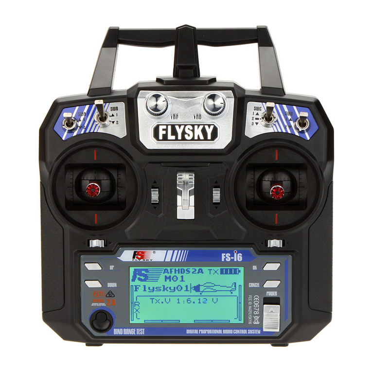
REMOTE FUNCTIONS
Power On/O
Backlit
LCD Screen
Idle/Resume
Left/Right
Steering* 2 AA Batteries
Replace by
removing
two screws
Lanyard Loop
Max Throttle
Faster
Slower
StrikeModeTM
POWER
Power On
To power on your remote, push the Power On/O button for one
second. You will see TROLL Master on the screen. Select any function to
start using the remote.
Power O
To power o your remote, push the Power ON/O button for two
seconds until the display clears.
Sleep Mode
If you do not touch any buttons for one minute, the remote will go into
sleep mode. In order to wake it, touch any button on the remote and it
will resume to your last used function.
Batteries
The remote runs on two standard AA batteries. You will get a ‘Low
Battery’ indication on the screen when it is time to change them.

Page 5
THROTTLE CONTROL
You have a range of 1-250 to adjust your speed. This does not correlate
to your actual GPS speed. Use an external GPS in order to get an accu-
rate speed reading for your situation.
Incremental Speed Adjustment
There are two buttons to control your speed, a rabbit icon for increasing
your speed and a turtle icon to decrease your speed. Press one time on
the corresponding button to change your speed in single increments.
Rapid Speed Adjustment
If you hold down on either speed button for two seconds your incre-
ments will increase by 10. Release the button and then press once
again to go back to increasing by single increments.
Feature buttons
These two buttons will allow you to max out the throttle control
[approx. 80% of factory throttle], or return to idle.
Max Throttle
To use this feature you need to depress and hold the Max Throttle
button. You will see ‘Max Throttle’ appear on the screen while it is being
held down, and your motor will increase speed and stay at that Max
Throttle as long as the button is held down. To return to your previous
speed setting, release the button.
Idle/Resume
To use this feature, press the Idle button. When you do, the throttle will
drop to the 000 setting and it will say ‘Idle 000’on the remote. To resume
your previous setting press the Idle button again. You will see‘Resume
XXX’. The XXX will be the setting you had last been congured for.
STEERING CONTROL
When your unit is connected to a Panther Electro Steer (sold sepa-
rately,) you are able to remotely steer your kicker motor. Press once on
the Left or Right Arrow button on the remote to move in small incre-
ments. If you hold down the button it will move in larger increments.
See Installation Steps for more details.

Page 6
STRIKE MODETM
Strike Mode is an automatic speed control function that utters the
shing lure at timed intervals. The user can select one of four prepro-
grammed speed proles A,B,C or X
Entering Strike Mode
Starting from Manual Mode where an initial baseline trolling speed
has been established, press the‘PRO’ button to enter prole selection.
Display will show‘A’with ashing ‘PRO’. Press ‘PRO’ button again to
conrm prole A selection or press ‘Rabbit Up’or ‘Turtle Down’ buttons
to cycle between the proles: A,B,C & X. Once an alternative prole is
displayed, press‘PRO’ button again to conrm this prole selection.
Display will then show prole name e.g. ‘A PRO’ followed by ‘ACTIVE’
Strike Mode Proles
o Prole A: Short burst of increased speed followed by return to
baseline speed. Prole repeats every 2 min
o Prole B: Short burst of increased speed followed by return to
baseline speed. Prole repeats every 4 min
o Prole C: Short burst of increased speed followed by return to
baseline speed. Prole repeats every 6 min
o Prole X: Stronger burst of increased speed followed by return to
baseline speed. Prole repeats every 4 min
Exiting Strike Mode
Press and hold ‘PRO’ button for 3 seconds or press ‘Power’ button once.
Engine throttle will return to original baseline speed.

Page 7
INSTALLATION INSTRUCTIONS
1. Packaged in the hardware kit that you purchased with your ProAngler
is an install manual that explains in detail how to Install your servo and
throttle rod.
2. Your wireless receiver needs to be placed in a location where it will not
be exposed to constant water exposure. A battery compartment, rod
box, anything similar would be a good location. Keep in mind that this
location also needs to allow for the wires to be able to reach the battery,
servo, steering, etc. As an additional consideration, the signal between
your remote and receiver is designed to work within a ~30ft (9.1m) range
even inside of an enclosed location. Once you nd a suitable location,
use the mounting holes and appropriate hardware to secure it.
3. The main power leads connect directly the 12V battery using the ring
connectors provided. Red to +ve terminal, Black to -ve terminal. The
positive wire includes a standard 15A ATO style blade fuse.
4. The ACC+ Switched power should be connected to a +ve 12V switched
power source at the helm station. When the outboard engine is not in
use, the switched power should be powered down.
5. The servo wire from your receiver needs to be routed to the servo
mounted on your kicker motor. NOTE: If you need an extension to your
servo cable, visit trollmasters.com and look for the Parts Shop link.
There is a 10ft (3m) extension available. To minimize the impact of EMI,
take care to route and secure servo cable as far away as practical from
the spark plug wires.
6. (Optional Steering Device) Route the steering cable 6ft (1.8m) from
your receiver to the location of your Panther Electro Steer motor and
connect the 2-Way molded connector until they are fully engaged. Do
not plug into the 3-way molded connector in an existing relay control.
7. NOTE: Keep in mind that depending on which side your electro steer is
mounted on your kicker motor the turn controls might be reversed. To
change this you can reverse the polarity of the connection. First, discon-
nect the unit from the battery. Then cut the wires between the receiver
and connector. Now reconnect the wires, but connect red to black and
black to red. Be sure to use proper connections, like Butt T splices or
wire nuts.
8. Pair your remote to your receiver. Push the pairing button on the
receiver and you will see a solid activity light. Then press any button on
the remote. Once the light goes o your remote is paired. It will always

Page 8
SERVICE AND WARRANTY
Should your unit ever require service, please do not return the product
to your dealer. Please call the number below for special instructions on
shipping and handling. Please call between 9:00 am - 4:00 pm (Central
Standard Time) Monday through Friday. If service is required and
covered by warranty, it will be repaired or replaced as described below.
If service is required and not covered by warranty, (such as damage
caused from improper trailering or from water intrusion through the
breather tube), replacement parts are available for purchase and may
be paid for by Visa or MasterCard.
The warranty coverage on this equipment is limited to the terms set
forth below: CMP Group LTD. warrants this product to be free of defects
in material and workmanship for a period of ONE (1) YEAR from the
date of original retail purchase. Positive proof of date of purchase
is required for warranty service. If service is required and covered
by warranty, the unit will be repaired or replaced with new or factory
pair to the most recent unit. If you need to replace your remote, follow-
ing this step will pair your new remote and does not store you older
remote.
9. Once everything is connected and paired, ensure that operation is cor-
rectly working by using your remote to verify that the servo (and steer-
ing) are responding to inputs. Once this has been veried, tie down any
loose cables securely.
TROUBLESHOOTING
Inputs to remote do not cause the servo or steering to respond.
• Double check that your battery that is charged.
• Verify that your power cables are connected securely.
• Try pairing the remote one more time and ensure that the Activity
Light comes on to verify power.
• Check that the screen on the remote is in fact showing any kind of
text after pushing the power button. For testing ensure there is a
clear line of sight between the remote and the receiver. Once that
works place back in your preferred location and retest.

Page 9
rebuilt parts at no charge. The defective components must be returned
to the address specied, with shipping charges prepaid. Be sure to
include your name, address, telephone number and a copy of the sales
receipt showing the date of original retail purchase. All sales receipts are
subject to verication.
This warranty does not apply if the unit has been damaged by accident,
abuse, misuse, poor installation or misapplication, or if it has been modi-
ed from its original condition, or if any serial number has been removed
or defaced or altered. This warranty does not cover any expense to
remove or reinstall the unit or any of its components. If a returned
unit is not covered by warranty, the sender will be notied and given an
estimate of the charges to repair or replace the unit, together with the
return shipping charges.
THIS WARRANTY DOES NOT COVER SPECIAL, INCIDENTAL, OR CONSE-
QUENTIAL DAMAGES RESULTING FROM ANY BREACH OF WARRANTY,
OR UNDER ANY OTHER LEGAL THEORY, INCLUDING BUT NOT LIMITED
TO DAMAGE TO OR REPLACEMENT OF OTHER EQUIPMENT AND PROP-
ERTY. THE WARRANTY AND REMEDIES SET FORTH ARE EXCLUSIVE AND
IN LIEU OF ALL OTHERS, WHETHER ORAL OR WRITTEN, EXPRESS OR
IMPLIED. DUE TO THE SPECIAL AND UNIQUE CONDITIONS THAT MAY
EXIST IN EACH APPLICATION, THE MANUFACTURER SPECIFICALLY DIS-
CLAIMS ANY AND ALL IMPLIED WARRANTIES OF MERCHANTABILITY
AND FITNESS FOR A PARTICULAR PURPOSE. NO DEALER, AGENT OR
EMPLOYEE IS AUTHORIZED TO MAKE ANY MODIFICATION, EXTENSION
OR ADDITION TO THIS WARRANTY.
Some states do not allow exclusion of incidental or consequential
damages, so the above exclusions may not apply to you. This warranty
gives you specic legal rights, and you may also have other legal rights,
which may vary from state to state.
FOR SERVICE CALL +1 (757) 916-9676
CMP Group LTD.
7733 Progress Way, Delta, BC,
Canada V4G 1A3
https://trollmasters.com/

Page 10
LANYARD STOP SWITCH EXTENSION
The purpose of a lanyard stop switch is to turn o the engine when the
operator moves far enough away from the operator’s position (as in acci-
dental ejection from the operator’s position) to activate the switch. Please
refer to your Lanyard Stop Switch (or similar) section of your manual for
all information related to that safety feature. This documents is NOT a
replacement for that section of your owner’s manual.
With the TROLLMaster being a wireless solution you can move farther
than the standard lanyard length that is provided with a standard Lanyard
Stop Switch. This extension is provided in the package for you to be able
to move farther than the standard 122cm and 152cm (4 and 5 feet). This
extension should be connected to the clip end of the existing stop switch
lanyard and the other end clipped to the operator securely.
There are more robust solutions that can be used in place of the lanyard
extension if so desired. Doing an Internet search of “Wireless Marine
Safety Devices” would direct you to such items available. TROLLMaster
does not endorse or support any one solution.
One other item for safety to keep in mind is the use of the Steering Fric-
tion Control, especially on Tiller Steering outboards. This should be set
just high enough that the engine won’t turn on its own without input
from the operator, at any tilt position. If this is set too low and the opera-
tor lets go of the tiller (i.e., to grab a hat blowing o their head) the engine
can turn abruptly and possibly throw the operator out of the boat.
WARNING
To avoid serious injury or death due to ejection from
the boat, always attach the emergency safety switch
lanyard (with or without the extension) to the switch
& the operator. In addition always have the outboard
steering friction adjusted as instructed.

Page 11
FCC: 2AILDTMPRO3PLUS
IC: 21604TMPRO3PS
This device complies with Part 15 of the FCC Rules. Operation is subject to
the following two conditions:
(1) This device may not cause harmful interference, and
(2) This device must accept any interference received, including interfer-
ence that may cause undesired operation.
Federal Communication Commission Interference Statement Indus-
try Canada Statement
This device complies with Industry Canada licence-exempt RSS standard.
Operation is subject to the following two conditions:
(1) this device may not cause interference, and
(2) this device must accept any interference, including interference that
may cause undesired operation of the device.
Le present appareil est conforme aux CNR d’Industrie Canada applicables aux
appareils radio exempts de licence.
L’exploitation est autorisee aux deux conditions suivantes :
(1) l’appareil ne doit pas produire de brouillage, et
(2) l’utilisateur de l’appareil doit accepter tout brouillage radioelectrique subi,
meme si le brouillage est susceptible d’en compromettre le fonctionnement.

Expand and enhance your shing experience with
these CMP Group brands:
Solutions for motor mounting, remote steering, tilt
& trim, shallow water anchors, and security systems.
Premium marine cathodic protection for boats,
marine structures, and boat equipment in three
dierent alloys
Wide range of dock and mooring products such
as fenders, buoys, cleats, ladders, and dock lines,
as well as dock carts and solar lighting.
World class marine anchor chain, anchor rodes,
lines, and shackles for every kind of boat.
Designed by a sailor for fellow boaters, Rocna
anchors have the highholding power in a wide
range of seabeds.
Autopilot Drive Systems that are engineered to
deliver unparalleled performance and years of
reliable service on a wide range of vessels.
Premium ropes made in Canada with mildew and
UV-resistant high-tensile nylon.
Auxiliary outboard motor steer systems.
www.cmpgroup.net
02MANTMPROANGLER V1
12 pages, 5.5 x 8.5 IN
Table of contents
Popular Control System manuals by other brands
Meteo Control
Meteo Control WEB’LOG RESIDENTIAL quick start guide

BJ Live
BJ Live Participation box user guide
Spraying Systems
Spraying Systems TeeJet TECHNOLOGIES BoomPilot installation manual
BM PRO
BM PRO RVMaster Help guide
Crestron Electronics
Crestron Electronics 4 Series product manual
protech
protech CM 5000D instructions
