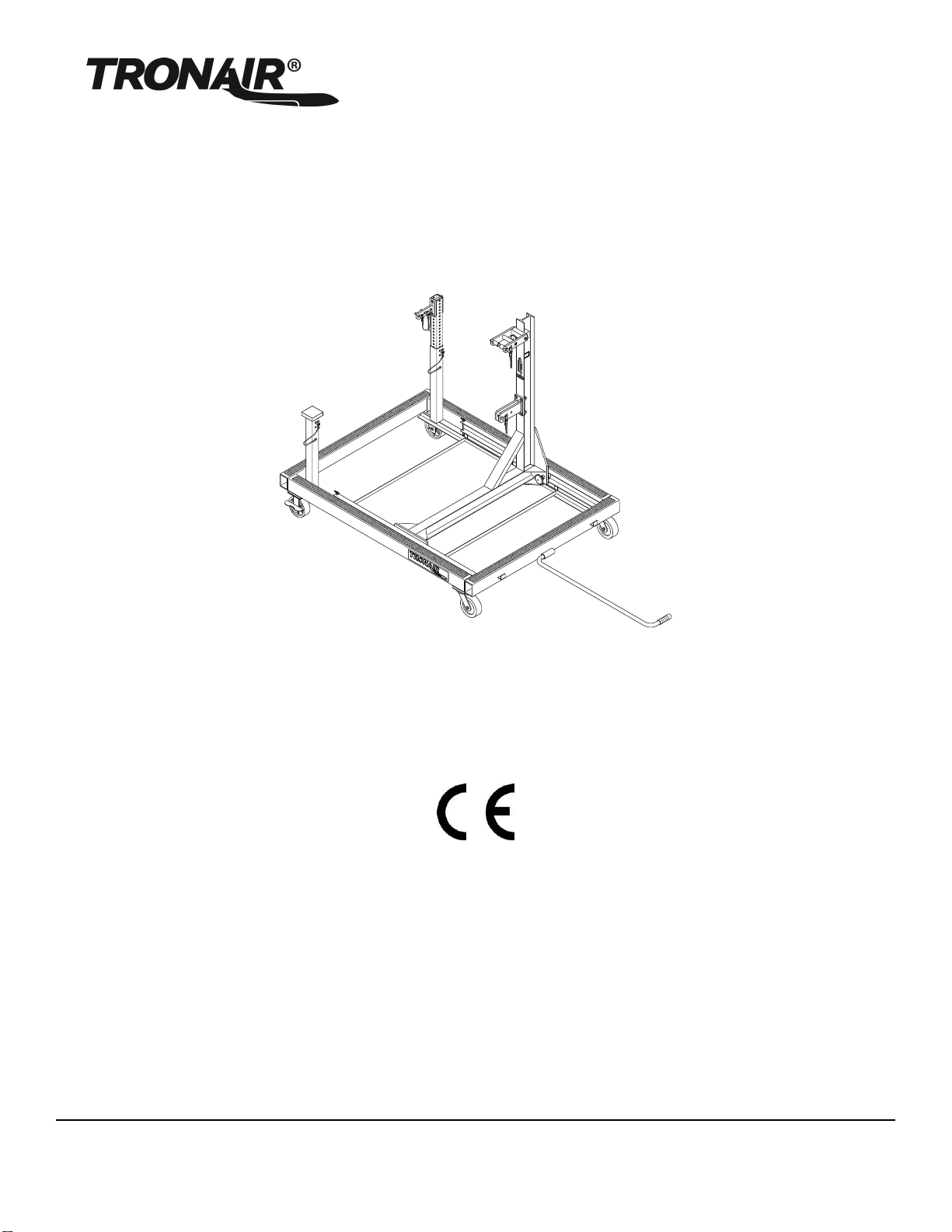
Tronair 08-2030-0000 Installation and operating instructions

OPERATION & SERVICE MANUAL
Tronair, Inc. Phone: (419) 866-6301 | 800-426-6301
1740 Eber Rd Web: www.tronair.com
Model: 08-2030-0000
Engine Work Stand
05/2007 –Rev. 03
Includes Illustrated Parts Lists

REVISION DATE TEXT AFFECTED
03 05/2007 Modified Parts List and Part Lists Illustrations

Model: 08-2030-0000
Engine Work Stand
05/2007 | Rev. 03
TABLE OF CONTENTS PAGE
1.0 PRODUCT INFORMATION ..............................................................................................................................................1
1.1 DESCRIPTION....................................................................................................................................................1
1.2 MODEL & SERIAL NUMBER..............................................................................................................................1
1.3 MANUFACTURER..............................................................................................................................................1
1.4 USAGE ...............................................................................................................................................................1
1.5 SPECIFICATIONS..............................................................................................................................................1
2.0 ASSEMBLY INSTRUCTIONS...........................................................................................................................................2
2.1 ASSEMBLY STEPS............................................................................................................................................2
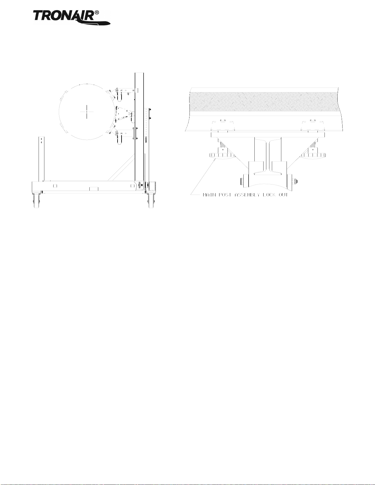
2.1.1 Install Main Post Assembly .................................................................................................................................2
2.1.2 Install Rear Engine Support Post........................................................................................................................2
2.2 PRE-USE CHECKS............................................................................................................................................2
3.0 TRAINING.........................................................................................................................................................................2
3.1 TRAINING REQUIREMENTS.............................................................................................................................2
3.2 TRAINING PROGRAM .......................................................................................................................................2
3.3 OPERATOR TRAINING......................................................................................................................................2
4.0 OPERATION.....................................................................................................................................................................3
5.0 MAINTENANCE................................................................................................................................................................4
5.1 PERIODIC INSPECTION....................................................................................................................................4
5.2 LOAD TEST........................................................................................................................................................4
6.0 PROVISION OF SPARES.................................................................................................................................................4
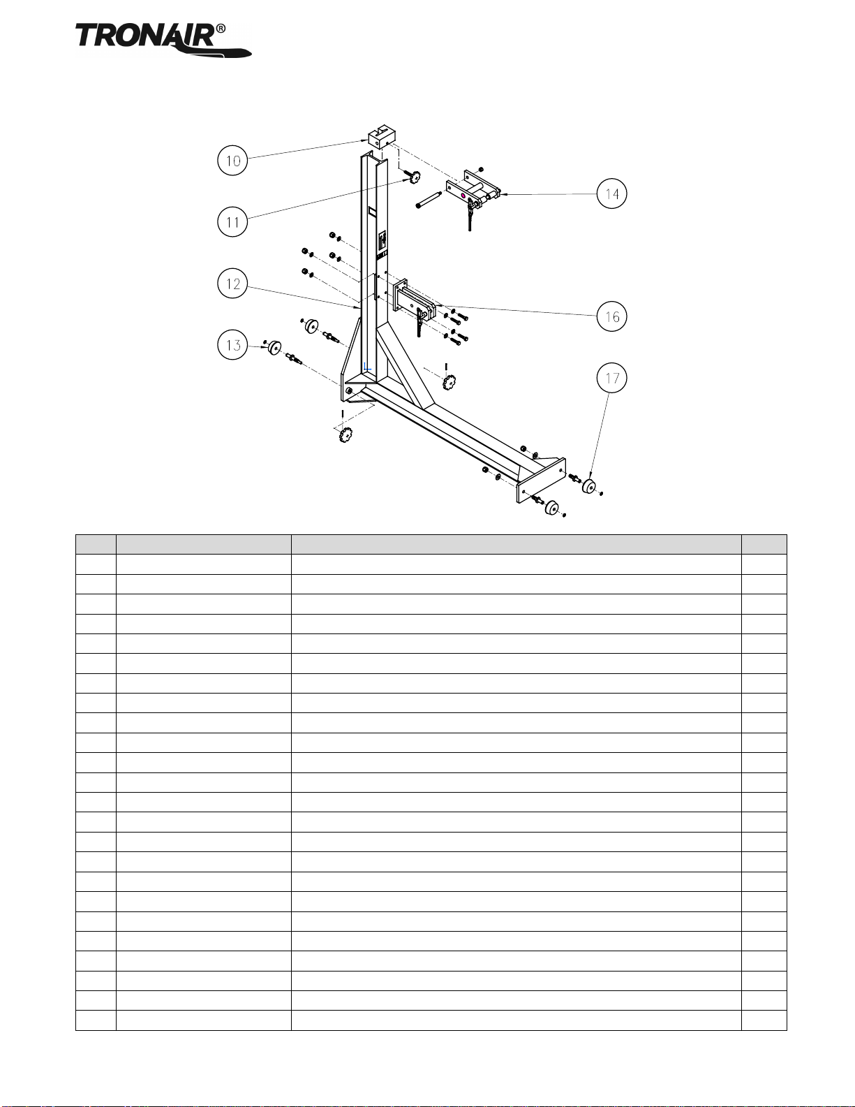
6.1 SOURCE OF SPARE PARTS.............................................................................................................................4
6.2 RECOMMENDED SPARE PARTS LISTS ..........................................................................................................4
7.0 GUARANTEES/LIMITATION OF LIABILITY....................................................................................................................5

Model: 08-2030-0000
Engine Work Stand
05/2007 | Rev. 03 Page | 1
This product can not be modified without the written approval of Tronair, Inc. Any modifications done without written approval
voids all warranties and releases Tronair, Inc., its suppliers, distributors, employees, or financial institutions from any liability
from consequences that may occur. Only Tronair OEM replacement parts shall be used.
1.0 PRODUCT INFORMATION
1.1 DESCRIPTION
The Tronair engine work stand incorporates the following quality features:
Heavy duty steel construction
Easily maneuverable
Can be fixed into static position with rigid caster wheel brakes
Oil pan to capture excess fluid
Easily converted to accept left or right hand engines
Multiple Engine Adaptability (Engine adapter kits sold separately)
1.2 MODEL & SERIAL NUMBER
Reference nameplate on unit
1.3 MANUFACTURER
TRONAIR, Inc. Telephone: (419) 866-6301 or 800-426-6301
1740 Eber Road Fax: (419) 867-0634
Website: www.tronair.com
1.4 USAGE
This stand allows full access to the engine for maintenance purposes by utilizing the same attach points used on the aircraft.
In order to adapt the engine to the stand, the appropriate adapter kit must be used. Refer to the table below to select the
correct adapter kit.
The purpose of this engine stand is to allow mechanics easy access to any part of the engine system during engine inspection
and maintenance procedures. A “three-point” mounting system via front mounting pads and rear support post into the engine
stand make access to the engine possible.
REFERENCE AVAILABLE ENGINE ADAPTER KITS
ENGINE KIT NUMBER
DESCRIPTION
FRONT
MOUNT
QTY
REAR MOUNT
QTY
K-2685
PW-530A Engine
Z-3799
2
Z-3798
1
K-2769
PW-545A Engine
Z-3792
2
Z-3796
1
K-2770
TFE-731 Engine
Z-3790
2
Z-3801
1
K-2776
JT15D-1 Engine
Z-3815
2
Z-3817
1
K-3068
PW-535 Engine
Z-3792
2
Z-4332
1
1.5 SPECIFICATIONS
Weight: 485 lbs.
Length: 73½ inches (without Towbar)
Width: 55 inches
Height: 60¼ inches

Model: 08-2030-0000
Engine Work Stand
05/2007 | Rev. 03 Page | 2
2.0 ASSEMBLY INSTRUCTIONS
This product should be assembled and/or repaired using good workmanship practices and proper tools.
2.1 ASSEMBLY STEPS
The main post assembly and rear mounting support are
reversible for mounting left or right hand engines. The engine
stand is designed to handle various length engines by way of
a roller mounted main post assembly that allows for
adjustability of 15-5/8 inches to 55 inches from the rear engine
attach point. The rear attach post height is fully adjustable
through 22" in one-half inch increments.
2.1.1 Install Main Post Assembly
1. Remove rail pins.
2. Orientate main post assembly for left or right hand
engine.
3. Rotate main post assembly to allow the lead rollers to
lead into the support rails in the base and tilt main post
assembly until the main post assembly is in the vertical
position. (See Figure 1).
4. Roll main post assembly forward until located in
approximate position for engine to be mounted.
5. Re-install rail pins.
2.1.2 Install Rear Engine Support Post
1. Orientate rear engine support post for left on right hand engine
2. Locate rear support to approximate engine, attach height and pin into place with post pin.
2.2 PRE-USE CHECKS
Refer to the parts list and illustration attached to identify and assure that all parts are present.
Generally check the entire unit to assure the tightness of all nuts and bolts, etc.
3.0 TRAINING
3.1 TRAINING REQUIREMENTS
The employer of the operator is responsible for providing a training program sufficient for the safe operation of the unit.
3.2 TRAINING PROGRAM
The employer provided operator training program should cover safety procedures concerning use of the unit in and around the
intended aircraft at the intended aircraft servicing location.
3.3 OPERATOR TRAINING
The operator training should provide the required training for safe operation of the unit.
NOTE: Maintenance and Trouble Shooting are to be performed by a skilled and trained technician.
FIGURE 1

Model: 08-2030-0000
Engine Work Stand
05/2007 | Rev. 03 Page | 3
4.0 OPERATION
1. Engine stand requires use of specific engine adapter kit (not included with engine stand).
2. Attach appropriate sling (not included with engine stand) to engine and remove from aircraft according to the
manufacturer’s instructions.
3. Attach the front and rear mounting adapters to the engine. (See Figure 2)
4. Lock caster brakes on stand.
5. Align the engine with the main post assembly on the engine stand. Be sure that the front of the engine is positioned
towards the main post assembly.
6. Carefully move engine into stand and make the final position adjustment of the main post assembly relative to the fixed
rear post location.
7. Attach front and rear engine mount adapters to the engine stand attach points. Make all final adjustments to allow for
good engine positioning on engine stand.
8. Tighten down main post assembly lock out screws by alternating until both are tight. (See Figure 3)
9. Remove hoist from engine and work area.
10. Reverse steps 1 through 9 to remove engine.
FIGURE 2
FIGURE 3

Model: 08-2030-0000
Engine Work Stand
05/2007 | Rev. 03 Page | 4
5.0 MAINTENANCE
5.1 PERIODIC INSPECTION
A qualified inspector shall performa complete inspection at the following intervals
SERVICE
INTERVAL
Normal
Yearly
Inspect equipment at site of use. Operation with various weights within the rated load limit,or
uniform loads less than 65 percent of rated load.
Heavy
Semi-Annual
Inspect equipment at site of use unlessexternal conditions indicate that disassembly should
be done to permit detailed inspection. Operation within the rated load limit that exceeds
normalservice.
Severe
Quarterly
Inspect equipment at site of use unlessexternal conditions indicate that disassembly should
be done to permit detailed inspection. Operation at normal or heavy service under abnormal
operating conditions.
Special/
Infrequent
As recommended by a qualified person before the first such use and as directed by the qualified person for
any subsequent uses
1. Before each use visually inspect unit to ensure all components are present and functional
-All bolts & nuts are secure
-Check for wear on t-handle ball-lok pins. Replace as necessary
-All casters & locks are operational
-No bent or, broken components WARNING!
Ensure stand components are free of damage and or excessive wear. Never use stand if any component is
bent or broken
2. Periodically:
-Lubricate swivel caster bearing race and caster wheels with multi-purpose grease
-Lubricate flange bearing assembly with multi-purpose grease
-Adjust toggle clamp spindles as required to ensure clamping
3. Annually:
a. Safely perform load test
5.2 LOAD TEST
It is recommended to send Equipment to Manufacturer or Authorized Service Center for Recertification.
The rated capacity shall not be more than 80 percent of the maximum load sustained during the test. Test loads shall not be
more than 125 percent of the rated capacity unless otherwise recommended by the manufacturer. Test weights shall be
accurate to within -5 percent, +0 percent of stipulatedvalues.
1. Overall visual inspection.
2. Install test weight equivalent to500 lbs
3. Hold the load for two (2) minutes.
4. Remove load and visually inspect stand for any signs of wear or failure
6.0 PROVISION OF SPARES
6.1 SOURCE OF SPARE PARTS
Spare parts may be obtained from the manufacturer:
TRONAIR, Inc. Telephone: (419) 866-6301 or 800-426-6301
1740 Eber Road Fax: (419) 867-0634
Website: www.tronair.com
6.2 RECOMMENDED SPARE PARTS LISTS
Reference the following page for Replacement Parts available.

Model: 08-2030-0000
Engine Work Stand
05/2007 | Rev. 03 Page | 5
7.0 GUARANTEES/LIMITATION OF LIABILITY
Tronair products are warranted to be free of manufacturing or material defects for a period of one year after shipment to the
original customer. This is solely limited to the repair or replacement of defective components. This warranty does not cover the
following items:
a) Parts required for normal maintenance
b) Parts covered by a component manufacturers warranty
c) Replacement parts have a 90-day warranty from date of shipment
If you have a problem that may require service, contact Tronair immediately. Do not attempt to repair or disassemble a product
without first contacting Tronair, any action may affect warranty coverage. When you contact Tronair be prepared to provide the
following information:
a) Product Model Number
b) Product Serial Number
c) Description of the problem
If warranty coverage is approved, either replacement parts will be sent or the product will have to be returned to Tronair for
repairs. If the product is to be returned, a Return Material Authorization (RMA) number will be issued for reference purposes
on any shipping documents. Failure to obtain a RMA in advance of returning an item will result in a service fee. A decision on
the extent of warranty coverage on returned products is reserved pending inspection at Tronair. Any shipments to Tronair must
be shipped freight prepaid. Freight costs on shipments to customers will be paid by Tronair on any warranty claims only. Any
unauthorized modification of the Tronair products or use of the Tronair products in violation of cautions and warnings in any
manual (including updates) or safety bulletins published or delivered by Tronair will immediately void any warranty, express or
implied.
The obligations of Tronair expressly stated herein are in lieu of all other warranties or conditions expressed or implied. Any
unauthorized modification of the Tronair products or use of the Tronair products in violations of cautions and
warnings in any manual (including updates) or safety bulletins published or delivered by Tronair will immediately
void any warranty, express or implied and Tronair disclaims any and all liability for injury (WITHOUT LIMITATION and
including DEATH), loss or damage arising from or relating to such misuse.

Model: 08-2030-0000
Engine Work Stand
05/2007 | Rev. 03 Page | 6
Parts List
When ordering replacement parts/kits, please specify model, serial number and color of your unit.
Item
Part Number
Description
Qty
2
Z-3769-01
Weldment, Base
1
3
Z-3810
Assembly, Oil Pan
1
5
Z-2822
Assembly, Handle
1
6
G-1310-0435
Pin, Ball Lok-T, 1/4" diameter x 3 1/2" long
2
7
G-1310-0630
Pin, Ball Lok-T, 3/8" Diameter x 3.0" long
1
8
TS155-01*030.00
Tube
1
9
Z-5033
Assembly, Bumper Pad
1
K-2335
Kit, Rigid Caster Replacement; consists of:
1
G-1100-107506
Bolt, Hex Head, Grade 5, 3/8-24
4
G-1250-1070N
Flatwasher, 3/8 Narrow
4
G-1251-1070R
Lockwasher, 3/8 Regular
4
U-1056
Caster, Rigid
1
K-2336
Kit, Swivel Caster Replacement; consists of:
4
G-1100-107506
Bolt, Hex Head, Grade 5, 3/8-24
4
G-1250-1070N
Flatwasher, 3/8 Narrow
4
G-1251-1070R
Lockwasher, 3/8 Regular
4
U-1057
Caster, Swivel
1
NOTE: All kits include complete mounting hardware and any special mount components.

Model: 08-2030-0000
Engine Work Stand
05/2007 | Rev. 03 Page | 7
Parts List
When ordering replacement parts/kits, please specify model, serial number and color of your unit.
Item
Part Number
Description
Qty
10
J-2713
Block, Slide
1
11
H-2167
Assembly, Hand Knob
1
12
Z-3776-01
Weldment, Beam
1
K-2771
Kit, Pivot Support Replacement; consists of:
14
G-1155-107250
Screw, Socket Head Shoulder, 1/2" diameter
1
G-1202-1070
Stopnut, 3/8-16 Elastic
1
Z-3807
Assembly, Pivot Support
1
K-2772
Kit, Lower Support Replacement; consists of:
16
G-1202-1075
Stopnut, 3/8-24 Elastic
4
G-1250-1070N
Flatwasher, 3/8 Narrow
8
G-1420-107516
Bolt, Hex Head, Grade 8, 3/8-24
4
Z-3806
Assembly, Lower Support
1
K-2774
Kit, Brake Pin Replacement; consists of:
13
G-1300-13100
Pin, Roll, 1/8" diameter x 1" long
1
G-1395-02
Ring, External Retaining
1
H-2165
Handle, Modified
1
R-1772
Roller
1
R-1774
Pin, Brake
1
K-2775
Kit, Roller Pin Replacement; consists of:
17
G-1202-1095
Stopnut, 1/2-20 Elastic
1
G-1250-1090N
Flatwasher, 1/2 Narrow
1
G-1395-02
Ring, External Retaining
1
R-1772
Roller
1
R-1773
Pin, Roller
1
NOTE: All kits include complete mounting hardware and any special mount components.

Model: 08-2030-0000
Engine Work Stand
05/2007 | Rev. 03 Page | 8
Parts List
When ordering replacement parts/kits, please specify model, serial number and color of your unit.
Item
Part Number
Description
Qty
K-2773
Kit, Rear Mount Replacement; consists of:
18
G-1100-107536
Bolt, Hex Head, Grade 5, 3/8-24
2
G-1202-1075
Stopnut, 3/8-24 Elastic
2
G-1250-1070N
Flatwasher, 3/8 Narrow
4
J-2711
Plate, Bolt
1
Z-3808
Assembly, Rear Support
1
NOTE: All kits include complete mounting hardware and any special mount components.


APPENDIX I
Declaration of Conformity


Tronair, Inc. Phone: (419) 866-6301 | 800-426-6301
1740 Eber Rd Web: www.tronair.com
DECLARATION of CONFORMITY
The design, development and manufacture is in accordance with European Community guidelines
08-2030-000
Engine Work Stand
Relevant draft complied with by the machinery:
EN ISO 12100-1
Relevant standards complied with by the machinery:
EN ISO 12100-1
EN 1915-1:2001 (5.20)
Identification of person empowered to sign on behalf of the Manufacturer:
Quality Assurance Representative
Table of contents
Other Tronair Industrial Equipment manuals

Tronair
Tronair Batpak 11-6602-1000 Installation and operating instructions

Tronair
Tronair 06-4035-3600 Installation and operating instructions

Tronair
Tronair K-3864 Installation and operating instructions

Tronair
Tronair 06-5009C Series Installation and operating instructions

Tronair
Tronair Challenger 600 Installation and operating instructions

Tronair
Tronair JP30 Installation and operating instructions

Tronair
Tronair 01-0597-0000 Installation and operating instructions

Tronair
Tronair 01-0400-0000 Installation and operating instructions

Tronair
Tronair 06-5042 Series Installation and operating instructions

Tronair
Tronair Embraer 170 Installation and operating instructions